

Page 1
D6000 SERIES
Digital Transmitters
Modbus RTU, RS-485 Output
e-mail: info@omega.com
For latest product manuals:
omegamanual.info
Shop online at
omega.com
®
User’s Guide
®
Extended Warranty
Program
SM
MADE IN
Page 2

Servicing North America:
U.S.A.: Omega Engineering, Inc., One Omega Drive, P.O. Box 4047
ISO 9001 Certified Stamford, CT 06907-0047 USA
Toll Free: 1-800-826-6342 TEL: (203) 359-1660
FAX: (203) 359-7700 e-mail: info@omega.com
Canada: 976 Bergar
Laval (Quebec), H7L 5A1 Canada
Toll-Free: 1-800-826-6342 TEL: (514) 856-6928
FAX: (514) 856-6886 e-mail: info@omega.ca
For immediate technical or application assistance:
U.S.A. and Canada: Sales Service: 1-800-826-6342/1-800-TC-OMEGA
®
Customer Service: 1-800-622-2378/1-800-622-BEST
®
Engineering Service: 1-800-872-9436/1-800-USA-WHEN
®
Mexico/ En Español: 001 (203) 359-7803 FAX: 001 (203) 359-7807
Latin America: info@omega.com.mx e-mail: espanol@omega.com
Servicing Europe:
Benelux: Managed by the United Kingdom Office
Toll-Free: 0800 099 3344 TEL: +31 20 347 21 21
FAX: +31 20 643 46 43 e-mail: sales@omegaeng.nl
Czech Republic: Frystatska 184
733 01 Karviná, Czech Republic
Toll-Free: 0800-1-66342 TEL: +420-59-6311899
FAX: +420-59-6311114 e-mail: info@omegashop.cz
France: Managed by the United Kingdom Office
Toll-Free: 0800 466 342 TEL: +33 (0) 161 37 29 00
FAX: +33 (0) 130 57 54 27 e-mail: sales@omega.fr
Germany/ Austria: Daimlerstrasse 26
D-75392 Deckenpfronn, Germany
Toll-Free: 0800 6397678 TEL: +49 (0) 7056 9398-0
FAX: +49 (0) 7056 9398-29 e-mail: info@omega.de
United Kingdom: OMEGA Engineering Ltd.
ISO 9001 Certified One Omega Drive, River Bend Technology Centre, Northbank
Irlam, Manchester M44 5BD United Kingdom
Toll-Free: 0800-488-488 TEL: +44 (0) 161 777-6611
FAX: +44 (0) 161 777-6622 e-mail: sales@omega.co.uk
OMEGAnet®Online Service Internet e-mail
omega.com info@omega.com
It is the policy of OMEGA Engineering, Inc. to comply with all worldwide safety and EMC/EMI
regulations that apply. OMEGA is constantly pursuing certification of its products to the European New
Approach Directives. OMEGA will add the CE mark to every appropriate device upon certification.
The information contained in this document is believed to be correct, but OMEGA accepts no liability for any
errors it contains, and reserves the right to alter specifications without notice.
WARNING: These products are not designed for use in, and should not be used for, human applications.
®
Page 3

Overview
All D6000 series modules contain an EEPROM (Electrically Erasable Programmable Read Only
Memory) to store setup information and calibration constants. The EEPROM replaces the usual
array of calibration potentiometers and DIP switches used to specify baud rate, address, parity,
etc. The memory is nonvolatile which means that the information is retained even if power is
removed. No batteries are used so it is not necessary to open the module case.
The EEPROM provides tremendous system flexibility allowing all of the module’s setup
parameters to be configured remotely through the communications port without having to
physically change a switch or turn potentiometers. There is one minor drawback in using
EEPROM instead of switches; there is no visual indication of the setup information in the module.
To overcome this, each module has an input pin labeled DEFAULT*. By connecting this pin to
Ground, the module is placed in a known communications state called Default Mode.
The Default Mode settings are: 9600 baud, one start bit, eight data bits, one stop bit, and no
parity. The module will only answer to Modbus Slave address “01” in the Default Mode.
Grounding the DEFAULT* pin does not change any of the setups stored in EEPROM. The setup
information may be read to determine all of the setup parameters stored in the module.
Setup information in a module may be changed at any time or while in the Default Mode. The
baud rate and parity setups may be changed without affecting the Default Mode values of 9600
baud and no parity. When the DEFAULT* pin is released, the module automatically performs an
internal reset and configures itself to the baud rate and parity stored in the setup registers.
The Default Mode should only be used with a single module connected to a computer in order to
prevent communications data collisions with other modules on the serial port.
Page 4
Module Connections
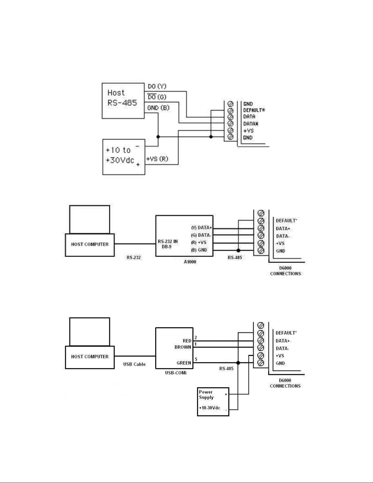
The D6000 series module must be connected to an RS-485 serial port for configuration. See
Figure 1.0 below for an overview of the required connections. Figure 2.0 details connections
between a D6000 and a A1000. Figure 3.0 details connections between a D6000 and a USBCOMi RS-485 serial converter. Note: No connections are required on the analog or digital I/O
pins to perform the module configuration.
Figure 1.0 General Overview, Default Mode and RS-485 Serial Connection.
Figure 2.0 D6000 to A1000 RS-232 to RS-485 Serial Converter in Default Mode.
Figure 3.0 D6000 to USB-COMi RS-485 Serial Converter in Default Mode.
Page 5

Software Installation
The first step towards “Getting Started” with your D6000 series module is to connect the module
to an RS-485 serial port using the one of the wiring connection diagrams above. Included within
the wiring connections is the “Default*” line being connected to the power supply ground. This
connection places the module in the “Default Mode”. The Default Mode forces the module into a
known communications state and is best utilized for configuring the module. The serial
communications parameters are: 9600 baud, one start bit, eight data bits, no parity and one stop
bit. The module will only answer to Modbus Slave address “1” (0x01).
Since the modules communicate via the Modbus RTU protocol, a Modbus Master program or the
D6000 series Utility Software will be required to change the module setup register values.
Modbus D6000 Series Utility Software is the best program to use when configuring a module. The
utility software reads the existing module information, displays the information in easy to
understand terms, allows changes to be made via drop-down list boxes and then writes the new
values back to the module.
The D6000 series Utility Software is provided free of charge on CDROM with a purchase order
and the latest version is always downloadable from www.omega.com. The utility software runs on
Windows based computers. Simply insert the CDROM into the CDROM drive, or download the
Setup.Exe file from the website, and then run the SETUP.EXE installation file. The software will
install and create a menu section called “Omega Utility Software” and the Utility Software will be
under that selection.
From the computer desktop select the “start” button, select “all programs”, select “Data
Acquisition” and then select “D6000 Series Utility Software” to run the utility software. A desktop
icon is also available to start the program. When the software opens then the first step is to
select, configure and open the serial communications port on the computer that the module is
connected to.
Select “Serial Port” in the upper left corner of the program screen and then select the proper
communications port and press the “Settings” button in the upper right hand corner of the screen.
Page 6

If the “Default*” line is connected to ground then select 9600 baud, no parity, eight data bits, one
stop bit, RTS Only handshaking and the Tx and Rx delays can be left in their default state.
Otherwise, adjust the settings to match the settings in the module.
Press the “Open Port” or “Update” button to complete the serial port configuration process.
Test Communications
After the utility software serial port has been configured the next step would be to check for valid
communications between the computer and the module. You must have valid communications
with the module before trying to perform the configuration process. To test the communications in
the Default Mode, set the Modbus Slave Address to 0x01. Set the Function selector to 03 and the
Register selection to 40001. Press the “Send” button to verify communications. A typical module
response is shown in the figure below.
Page 7

The figure above illustrates Modbus function 03 being sent to Slave address 01. Both the
command and response messages are displayed. This command/response format is provided for
troubleshooting purposes. It displays each byte of data being sent to and received from the
module. This information be a good troubleshooting tool or a good way to become familiar with
the Modbus RTU protocol.
The response data value from register 40001 is located in the RSP: line. The data value is a 16bit value located in the fourth and fifth bytes in the message (00 01). The “00 01” indicates that
the register value is 0001. Using the 7CH Current Input Modbus Register map, register 40001 is
the Modbus Slave address. In this example the module slave address value is read back as
0001.
In the event that the module was not detected by the software then the RSP: line would say
“RSP: Timeout – No Response Detected!”. Several things may contribute to this problem. Some
examples are no power to the module, bad RS-485 wiring connection(s), invalid port settings, or
RS-485 half-duplex handshaking problems all can cause timeout errors. Timeout errors must be
corrected before attempting to configure a module.
Page 8

Setup a Module
After a successful communications test has been performed then the module can be configured.
Select the type of module using the drop-down list box under “Quick Setup” in the lower left hand
corner of the screen. Then press the “Setup” button. A new screen (see below) will appear that
contains list of all the user-selectable module values. The screen below is for a seven channel
current input module.
Ensure that the Module Address in the lower left corner is 01 and then press the “Read Setup”
button. The screen will now populate using the configuration data read from the module.
The user-selectable values are displayed in an easy to understand format and new selections can
be made using the drop-down list boxes. The drop-down list boxes make the configuration
process easy and accurate because erroneous values cannot be entered.
Page 9

Once the new module configuration settings have been changed to meet the application
requirements then press the “Apply” button to transmit the new settings.
Scan Module Data Values
After the module has been properly configured, the analog input data values can be polled from
the module in order to verify the data from each channel. This feature is a good troubleshooting
or verification tool and should only be used when valid analog input signals are connected to the
module.
The analog input screens contain a “Scan” button that will enable the scanning process. Each
channel is read by requesting the data values from data registers within the module. The analog
input data registers can be found in the Modbus Register map and the data register locations are
specific to the module type.
The data values are returned in unsigned integer hexadecimal percentage of Full Scale format
where a value of 0x0000 represents the minus full scale input of the module. A value of 0xffff
represents the positive full-scale input of the module. These values can be viewed to check that
each channel is operating properly when analog signals are applied to the input terminals.
The data values can also be displayed as a numerical value. The utility software knows the plus
and minus full-scale input range for each channel. Using the raw hexadecimal percentage of fullscale data values the software can convert these readings to millivolts, milliamps, or temperature
readings. Simply uncheck the “Display Hex Values” selection underneath the channel readings to
display the numeric values.
The scanning process will also log and display the highest (peak) and lowest (valley) readings
that were recorded during the scanning process. This is just for indication purposes only.
A scan interval slide control is also provided to speed up or slow down the scanning process. This
slide control allows the channels to be scanned at intervals from 0.5 to 5 seconds.
Once the setup process is completed then the D6000 is ready to be installed into the application.
Page 10

WARRANTY/DISCLAIMER
OMEGA ENGINEERING, INC. warrants this unit to be free of defects in materials and workmanship for a
period of 13 months from date of purchase. OMEGA’s WARRANTY adds an additional one (1) month
grace period to the normal one (1) year product warranty to cover handling and shipping time. This
ensures that OMEGA’s customers receive maximum coverage on each product.
If the unit malfunctions, it must be returned to the factory for evaluation. OMEGA’s Customer Service
Department will issue an Authorized Return (AR) number immediately upon phone or written request.
Upon examination by OMEGA, if the unit is found to be defective, it will be repaired or replaced at no
charge. OMEGA’s WARRANTY does not apply to defects resulting from any action of the purchaser,
including but not limited to mishandling, improper interfacing, operation outside of design limits,
improper repair, or unauthorized modification. This WARRANTY is VOID if the unit shows evidence of
having been tampered with or shows evidence of having been damaged as a result of excessive corrosion;
or current, heat, moisture or vibration; improper specification; misapplication; misuse or other operating
conditions outside of OMEGA’s control. Components in which wear is not warranted, include but are not
limited to contact points, fuses, and triacs.
OMEGA is pleased to offer suggestions on the use of its various products. However,
OMEGA neither assumes responsibility for any omissions or errors nor assumes liability for any
damages that result from the use of its products in accordance with information provided by
OMEGA, either verbal or written. OMEGA warrants only that the parts manufactured by the
company will be as specified and free of defects. OMEGA MAKES NO OTHER WARRANTIES OR
REPRESENTATIONS OF ANY KIND WHATSOEVER, EXPRESSED OR IMPLIED, EXCEPT THAT OF
TITLE, AND ALL IMPLIED WARRANTIES INCLUDING ANY WARRANTY OF MERCHANTABILITY
AND FITNESS FOR A PARTICULAR PURPOSE ARE HEREBY DISCLAIMED. LIMITATION OF
LIABILITY: The remedies of purchaser set forth herein are exclusive, and the total liability of
OMEGA with respect to this order, whether based on contract, warranty, negligence,
indemnification, strict liability or otherwise, shall not exceed the purchase price of the
co mponen t upo n wh ich liabil ity is based. In no event shall OMEGA be lia ble for
consequential, incidental or special damages.
CONDITIONS: Equipment sold by OMEGA is not intended to be used, nor shall it be used: (1) as a “Basic
Component” under 10 CFR 21 (NRC), used in or with any nuclear installation or activity; or (2) in medical
applications or used on humans. Should any Product(s) be used in or with any nuclear installation or
activity, medical application, used on humans, or misused in any way, OMEGA assumes no responsibility
as set forth in our basic WARRANTY/DISCLAIMER language, and, additionally, purchaser will indemnify
OMEGA and hold OMEGA harmless from any liability or damage whatsoever arising out of the use of the
Product(s) in such a manner.
RETURN REQUESTS/INQUIRIES
Direct all warranty and repair requests/inquiries to the OMEGA Customer Service Department. BEFORE
RETURNING ANY PRODUCT(S) TO OMEGA, PURCHASER MUST OBTAIN AN AUTHORIZED RETURN
(AR) NUM B E R FROM OMEG A’ S C U STOMER SE RVI C E D E PARTMENT (IN O R D ER TO AVOID
PROCESSING DELAYS). The assigned AR number should then be marked on the outside of the return
package and on any correspondence.
The purchaser is responsible for shipping charges, freight, insurance and proper packaging to prevent
breakage in transit.
FOR WARRANTY
RETURNS, please have the
following information available BEFORE
contacting OMEGA:
1. Purchase Order number under which the product
was PURCHASED,
2. Model and serial number of the product under
warranty, and
3. Repair instructions and/or specific problems
relative to the product.
FOR NON-WARRANTY REPAIRS,
consult OMEGA
for current repair charges. Have the following
information available BEFORE contacting OMEGA:
1. Purchase Order number to cover the COST
of the repair,
2. Model and serial number of the product, and
3. Repair instructions and/or specific problems
relative to the product.
OMEGA’s policy is to make running changes, not model changes, whenever an improvement is possible. This affords
our customers the latest in technology and engineering.
OMEGA is a registered trademark of OMEGA ENGINEERING, INC.
© Copyright 2010 OMEGA ENGINEERING, INC. All rights reserved. This document may not be copied, photocopied,
reproduced, translated, or reduced to any electronic medium or machine-readable form, in whole or in part, without the
prior written consent of OMEGA ENGINEERING, INC.
Page 11

MQS5046/0612
Where Do I Find Everything I Need for
Process Measurement and Control?
OMEGA…Of Course!
Shop online at omega.com
TEMPERATURE
䡺⻬
Thermocouple, RTD & Thermistor Probes, Connectors, Panels & Assemblies
䡺⻬
Wire: Thermocouple, RTD & Thermistor
䡺⻬
Calibrators & Ice Point References
䡺⻬
Recorders, Controllers & Process Monitors
䡺⻬
Infrared Pyrometers
PRESSURE, STRAIN AND FORCE
䡺⻬
Transducers & Strain Gages
䡺⻬
Load Cells & Pressure Gages
䡺⻬
Displacement Transducers
䡺⻬
Instrumentation & Accessories
FLOW/LEVEL
䡺⻬
Rotameters, Gas Mass Flowmeters & Flow Computers
䡺⻬
Air Velocity Indicators
䡺⻬
Turbine/Paddlewheel Systems
䡺⻬
Totalizers & Batch Controllers
pH/CONDUCTIVITY
䡺⻬
pH Electrodes, Testers & Accessories
䡺⻬
Benchtop/Laboratory Meters
䡺⻬
Controllers, Calibrators, Simulators & Pumps
䡺⻬
Industrial pH & Conductivity Equipment
DATA ACQUISITION
䡺⻬
Data Acquisition & Engineering Software
䡺⻬
Communications-Based Acquisition Systems
䡺⻬
Plug-in Cards for Apple, IBM & Compatibles
䡺⻬
Data Logging Systems
䡺⻬
Recorders, Printers & Plotters
HEATERS
䡺⻬
Heating Cable
䡺⻬
Cartridge & Strip Heaters
䡺⻬
Immersion & Band Heaters
䡺⻬
Flexible Heaters
䡺⻬
Laboratory Heaters
ENVIRONMENTAL
MONITORING AND CONTROL
䡺⻬
Metering & Control Instrumentation
䡺⻬
Refractometers
䡺⻬
Pumps & Tubing
䡺⻬
Air, Soil & Water Monitors
䡺⻬
Industrial Water & Wastewater Treatment
䡺⻬
pH, Conductivity & Dissolved Oxygen Instruments
 Loading...