

Page 1

M789-038A 15 June 1999
Page 2

OMEGA Model CYD201/CYD208 User’s Manual
WARRANTY
OMEGA warrants this unit to be free of defects in materials and workmanship and to give
satisfactory service for a period of 13 months from date of purchase. OMEGA Warranty adds an
additional one (1) month grace period to the normal one (1) year product warranty to cover handling
and shipping time. This ensures that our Customers receive maximum coverage on each product. If
the unit should malfunction, it must be returned to the factory for evaluation. Our Customer Service
Department will issue an Authorized Return (AR) Number immediately upon phone or written
request. Upon examination by OMEGA, if the unit is found to be defective, it will be repaired or
replaced at no charge. However, this WARRANTY is VOID if the unit shows evidence of having
been tampered with or shows evidence of being damaged as a result of excessive current, heat,
moisture, vibration, or misuse. Components which wear or which are damaged by misuse are not
warranted. These include contact points, fuses, and triacs.
THERE ARE NOT WARRANTIES EXCEPT AS STATED HEREIN. THERE ARE NO OTHER
WARRANTIES, EXPRESSED OR IMPLIED, INCLUDING BUT NOT LIMITED TO THE IMPLIED
WARRANTIES OF MERCHANTABILITY AND OF F ITNESS FOR A PARTICULAR PURPOSE. IN
NO EVENT SHALL OMEGA ENGINEERING, INC. BE LIABLE FOR CONSEQUENTIAL,
INCIDENTAL, OR SPECIAL DAMAGES. THE BUYER'S SOLE REMEDY FOR ANY BREACH OF
THIS AGREEMENT BY OMEGA ENGINEERING, INC. , OR ANY BREACH OF ANY WARRANTY
BY OMEGA ENGINEERING, INC., SHALL NOT EX CEED THE PURCHASE PRICE PAID BY THE
PURCHASE TO OMEGA ENGINEERING, INC. FOR THE UNIT OR UNITS OR EQUIPMENT
DIRECTLY AFFECTED BY SUCH BREACH.
RETURN REQUESTS / INQUIRIES
Direct all warranty and repair requests/inquiries to the OMEGA Customer Service Department.
Call toll free in the USA and Canada: 1-800-622-2378; FAX: 203-359-7811.
International:
BEFORE RETURNING ANY PRODUCT(S) TO OMEGA,
(AR) NUMBER FROM OUR CUSTOMER SERVICE DEPARTMENT IN ORDER TO AVOID
PROCESSING DELAYS
return package and on any correspondence.
FOR WARRANTY RETURNS:
OMEGA:
1. P.O. Number under which the product was PURCHASED.
2. Model and serial number of the product under warranty.
3. Repair instruction and/or specific problems you are having with the product.
FOR NON-WARRANTY REPA IRS OR CALIB4RATIONS:
repair/calibration charges. Have the following information BEFORE contacting OMEGA:
1. Your P.O. Number to cover COST of the repair/calibration..
2. Model and serial number of the product under warranty.
3. Repair instruction and/or specific problems you are having with the product.
Every precaution for accuracy has been taken in the preparation of this manual, however, OMEGA
ENGINEERING, INC. neither assumes responsibility for any omissions or errors that may appear
nor assumes liability for any damages that result from the use of the products in accordance with
the information contained in the manual.
OMEGA policy is to make running changes, not model changes, whenever an improvement is
possible. That way, our Customers get the latest in technology and engineering.
OMEGA is a registered trademark of OMEGA ENGINEERING, INC.
203-359-1660; FAX; 203-359-7806.
OBTAIN AN AUTHORIZED RETURN
. The assigned AR number should then be marked on the outside of the
Please have the following information available BEFORE contacting
Consult OMEGA for current
© 1998 and 1999 OMEGA ENGINEERING, INC. All rights reserved including illustrations. Nothing
in this manual may be reproduced in any manner, either wholly or in part for any purpose
whatsoever without written permission from OMEGA ENGINEERING, INC. Printed in U.S.A.
A
Page 3

OMEGA Model CYD201/CYD208 User’s Manual
TABLE OF CONTENTS
Chapter/Paragraph Title Page
1 INTRODUCTION..........................................................................1-1
1.0 General.......................................................................1-1
1.1 Model CYD201/CYD208 System Description.............1-1
1.2 Handling Liquid Helium and Liquid Nitrogen..............1-3
1.2.1 Handling Cryogenic Storage Dewars......................1-3
1.2.2 LHe and LN
1.2.3 Recommended First Aid .........................................1-4
1.3 Electrostatic Discharge...............................................1-4
1.3.1 Identifying ESDS Components ...............................1-5
1.3.2 Handling ESDS Components..................................1-5
1.4 Safety Summary.........................................................1-5
1.5 Safety Symbols...........................................................1-6
2 INSTALLATION...........................................................................2-1
2.0 General.......................................................................2-1
2.1 Inspection and Unpacking..........................................2-1
2.2 Repackaging For Shipment........................................2-1
2.3 Power and Ground Requirements..............................2-2
2.4 Sensor Installation Recommendations.......................2-2
2.4.1 Two-Lead Vs. Four-Lead Measurements................2-3
2.4.2 Connecting Leads to the Sensor.............................2-4
2.4.3 Sensor Mounting.....................................................2-4
2.4.4 Measurement Errors Due to AC Noise....................2-5
2.5 Sensor Input Connections..........................................2-6
2.6 Sensor Curve Definition..............................................2-7
2.7 Rack Mounting............................................................2-7
2.8 Initial Power Up Sequence.........................................2-9
2.9 Power Up Errors.........................................................2-9
Safety Precautions............................1-3
2
3 OPERATION................................................................................3-1
3.0 General.......................................................................3-1
3.1 Units Key....................................................................3-1
3.2 Channel Key (Model CYD208 Only)...........................3-2
3.3 Scan Mode .................................................................3-2
3.4 Setting Dwell Times....................................................3-2
3.5 Alarm Operation .........................................................3-2
3.5.1 Alarm Setpoint ........................................................3-2
3.5.2 Latched and Unlatched Alarms...............................3-3
3.5.3 Alarm Fix Function (Model CYD208 Only)..............3-3
3.6 SoftCal™ Compensations..........................................3-3
3.6.1 SoftCal™ Calibration Procedure.............................3-4
3.6.2 Verifying SoftCal™ Operation.................................3-5
3.6.3 Erasing SoftCal™ Compensations .........................3-5
Table of Contents i
Page 4

OMEGA Model CYD201/CYD208 User’s Manual
TABLE OF CONTENTS (Continued)
Chapter/Paragraph Title Page
4 REMOTE OPERATION................................................................4-1
4.0 General.......................................................................4-1
4.1 Serial Interface ...........................................................4-1
4.1.1 Serial Interface Connections...................................4-1
4.1.2 Serial Interface Operation.......................................4-3
4.1.3 Sample Basic Program ...........................................4-3
4.1.4 Sample QuickBasic 4.0 Program............................4-4
4.2 Serial Interface Command Summary..........................4-4
5 SERVICE......................................................................................5-1
5.0 General.......................................................................5-1
5.1 Model CYD201 Rear Panel Connections ...................5-1
5.2 Model CYD208 Rear Panel Connections ...................5-2
5.3 Error Code Troubleshooting .......................................5-3
5.4 General Maintenance.................................................5-3
5.5 Fuse Replacement .....................................................5-4
5.6 Line Voltage Configuration.........................................5-4
5.7 Recalibration...............................................................5-5
5.7.1 Current Source Calibration......................................5-5
5.7.2 A/D Converter Calibration.......................................5-6
5.8 Serial Interface Cable and Adapters...........................5-6
6 OPTIONS AND ACCESSORIES..................................................6-1
6.0 General.......................................................................6-1
6.1 Accessories................................................................6-1
6.2 Wires ..........................................................................6-2
6.3 Sensors ......................................................................6-3
APPENDIX A – CURVE TABLES...................................................... A-1
A1.0 General......................................................................A-1
ii Table of Contents
Page 5

OMEGA Model CYD201/CYD208 User’s Manual
LIST OF ILLUSTRATIONS
Figure No. Title Page
1-1 Typical Cryogenic Dewar..........................................................1-3
2-1 Model CYD201 Sensor Connector J1 Details...........................2-6
2-2 Model CYD208 Sensor Connector J1 Details...........................2-6
2-3 Model 2090 Rack Mounting......................................................2-8
3-1 Model CYD201 Front Panel......................................................3-1
3-2 Model CYD208 Front Panel......................................................3-1
4-1 Serial I/O (RJ-11) Connector Pin Definitions............................4-2
4-2 Serial Interface Connections.....................................................4-2
5-1 Model CYD201 Rear Panel Connections..................................5-1
5-2 Model CYD208 Rear Panel Connections..................................5-2
5-3 Line Voltage Jumper Configuration ..........................................5-4
5-4 Calibration Connections............................................................5-5
5-5 Model CYD200-J10 RJ-11 Cable Assembly Wiring Details......5-6
5-6 Model CYD200-D RJ-11 to DB-25 Adapter Wiring Details.......5-6
5-7 Model CYD200-B RJ-11 to DE-9 Adapter Wiring Details .........5-3
6-1 Serial Interface Adapters..........................................................6-3
LIST OF TABLES
Table No. Title Page
1-1 Model CYD201/CYD208 Specifications....................................1-2
2-1 Line Voltage and Fuse Rating Selection...................................2-2
2-2 Model CYD201/CYD208 Temperature Curves.........................2-7
4-1 Serial Interface Specifications ..................................................4-1
A-1 Curve 0 - DT-500DI-8B Voltage-Temp. Characteristics........... A-1
A-2 Curve 1 - DT-500DI-8A Voltage-Temp. Characteristics........... A-2
A-3 Curve 2 - DT-500DRC-D Voltage-Temp. Characteristics ........ A-3
A-4 Curve 3 - DT-500DRC-E1 Voltage-Temp. Characteristics.......A-4
A-5 Curve 4 - CTI Diode Voltage-Temp. Characteristics................ A-5
A-6 Curve 5 - DT-500DI-8C Voltage-Temp. Characteristics .......... A-6
A-7 Curve 6 - CY-7 Voltage-Temp. Characteristics........................A-7
Table of Contents iii
Page 6

OMEGA Model CYD201/CYD208 User’s Manual
This Page Intentionally Left Blank
iv Table of Contents
Page 7

OMEGA Model CYD201/CYD208 User’s Manual
CHAPTER 1
INTRODUCTION
1.0 GENERAL
This chapter covers a general description of the Model CYD201/CYD208
(Paragraph 1.1), Handling Liquid Helium and Liquid Nitrogen (Paragraph 1.2),
Electrostatic Discharge (Paragraph 1.3), Safety Summary (Paragraph 1.4),
and Safety Symbols (Paragraph 1.5).
Due to the OMEGA commitment to continuous product improvement,
modifications may occur to the Model CYD201/CYD208 software with time.
Some of these changes result from Customer feedback about operation on
various cryogenic systems. We encourage comments or suggestions
regarding this instrument. Please return the instrument warranty card to
ensure receipt of future software updates.
1.1 MODEL CYD201/CYD208 GENERAL DESCRIPTION
Model CYD201/CYD208 Digital Thermometers are ideal to monitor critical
temperatures in chemical and materials research, superconductivity
measurements, and low temperature physics. The units feature:
• Broad Temperature Range: 1.4 K to 475 K (–272 °C to 202 °C).
• Single Channel (CYD201) and Eight Channel (CYD208) Models.
• For use with CY-7 Series, DT-500 Series, and other Silicon Diode
Sensors.
• System Accuracy (Instrument with Sensor) with SoftCal™ to within
±0.1 °C or better.
• Temperature display in °C, °F, K, or Sensor Voltage.
• High/Low Alarm Setpoint with Interfacing Alarm Contacts.
• Standard RS-232C Output of Temperature, Input of Settings, and
Alarm Status for Remote Operation.
Introduction 1-1
Page 8

OMEGA Model CYD201/CYD208 User’s Manual
Table 1-1. Model CYD201/CYD208 Specifications
Display:
Resolution:
Four-digit LED display
0.1 for values > 100 or < –100
0.01 for values between -100<T<100
Temperature Range:
1.4 K to 475 K without probe
23 K to 473 K with probe
System Accuracy:
To within ±0.1K from 177 K to 313 K.
To ±0.2 K or better from 30 K to 373 K.
±1.0 K above 373 K.
Sensor Excitation:
Repeatability:
Input Range:
Hi/Lo Alarm Setpoint:
Alarm Relay:
10 µA constant current
<50 mK
0 to 3 volts with a resolution of 0.1 mV
0.1° resolution
Single SPDT relay, rated 28 VDC or Peak AC, 0.25 A
(3 W max.)
Scan/Dwell:
The Model CYD208 automatically scans all eight channels
with selectable dwell times of 0 (skip), 5, 10, 30 and 60
seconds for each channel.
Connections:
Response Curves*:
Four-lead sensor connection (2 current, 2 voltage).
Standard Curve 10, DT-500DI-8A
(also -8B and -8C), DT-500DRC-D,
DT-500DRC-E1, and CTI Curve C.
* SOFTCAL™ qualified only for CY-7 Series diode sensors.
COMPUTER INTERFACE
Type:
RS-232C Serial Three Wire (Refer to Table 4-1).
MECHANICAL
Ambient Temperature Range:
18 to 28 °C (64 to 82 °F),
or 15 to 35 °C (59 to 95 °F) with reduced accuracy.
Power Requirements:
Dimensions:
Weight:
41 x 106 x 164 mm (1.61 x 4.18 x 6.45 inches).
0.5 kilogram (1.1 Pounds)
90-125 or 210-250 VAC, 50/60 Hz, 3 watts.
NOTES
Product Specifications subject to c hange without notice.
1.
System electronic temperature accurac y in a gi ven temperature range is the
2.
sum of the specifications given for input and out put. Sensor calibration errors
are not included.
1-2 Introduction
Page 9
OMEGA Model CYD201/CYD208 User’s Manual
1.2 HANDLING LIQUID HELIUM AND LIQUID NITROGEN
Helium and Nitrogen are colorless, odorless, and tasteless gases. They
liquefy when properly cooled. Liquid helium (LHe) and liquid nitrogen (LN
)
2
may be used in conjunction with the Model CYD201 or CYD208. Although
not explosive, there are certain safety considerations in the handling of LHe
and LN
.
2
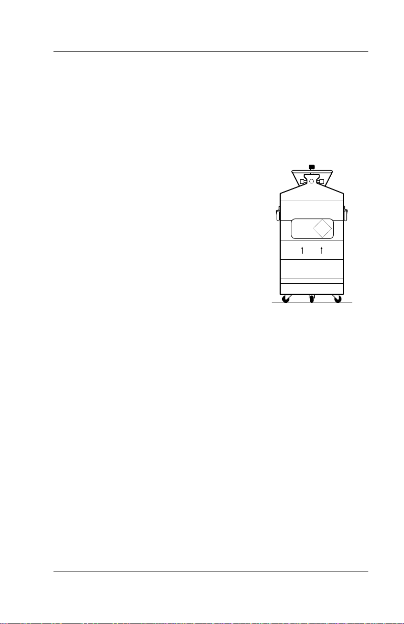
1.2.1 Handling Cryogenic Storage Dewars
Operate all cryogenic containers (dewars) in
accordance with manufacturer instructions. Safety
instructions are normally posted on the side of
each dewar. Keep cryogenic dewars in a wellventilated place, protected from the weather, and
away from heat sources. Figure 1-1 shows a
typical cryogenic dewar.
1.2.2 LHe and LN2 Safety Precautions
Transfer LHe and LN2 and operate storage dewar
controls in accordance with manufacturer/supplier
instructions. During transfer, follow all safety
precautions written on the storage dewar and
recommended by the manufacturer.
WARNING
• Liquid helium is a potential asphyxiant and can cause rapid
suffocation without warning. Store and use in an adequately
ventilated area. DO NOT vent the container in confined spaces. DO
NOT enter confined spaces where gas may be present unless area
is well-ventilated. If inhaled, remove to fresh air. If not breathing,
give artificial respiration. If breathing is difficult, give oxygen. Get
medical attention.
• Liquid helium can cause severe frostbite to exposed body parts. DO
NOT touch frosted pipes or valves. For frostbite, consult a
physician immediately. If a physician is unavailable, warm the
affected parts with water that is near body temperature.
Two essential safety aspects of handling LHe are adequate ventilation and
eye and skin protection. Although helium and nitrogen gases are non-toxic,
they are dangerous because they replace air in a normal breathing
atmosphere. Liquid helium is an even greater threat because a small
amount of liquid evaporates to create a large amount of gas. Store and
operate cryogenic dewars in open, well-ventilated areas.
Figure 1-1. Typical
NON-
MAGNETIC
NON-
LIQUID
FLAMMABLE
HELIUM
KEEP
UPRIGHT
Cryogenic Dewar
Introduction 1-3
Page 10

OMEGA Model CYD201/CYD208 User’s Manual
When transferring LHe and LN2, protect eyes and skin from accidental
contact with liquid or the cold gas issuing from it. Protect eyes with full face
shield or chemical splash goggles; safety glasses (even with side shields)
are inadequate. Always wear special cryogenic gloves (Tempshield
Cryo-Gloves
®
or equivalent) when handling anything that is, or may have
been, in contact with the liquid or cold gas, or with cold pipes or equipment.
Wear long sleeve shirts and cuffless trousers long enough to prevent liquid
from entering shoes.
1.2.3 Recommended First Aid
Post an appropriate Material Safety Data Sheet (MSDS) obtained from the
manufacturer/distributor at every site that stores and uses LHe and LN
MSDS specifies symptoms of overexposure and first aid.
If a person exhibits symptoms of asphyxia such as headache, drowsiness,
dizziness, excitation, excessive salivation, vomiting, or unconsciousness,
remove to fresh air. If breathing is difficult, give oxygen. If breathing stops,
give artificial respiration. Call a physician immediately.
If exposure to cryogenic liquids or cold gases occurs, restore tissue to
normal body temperature (98.6°F) by bathing it in warm water not exceeding
105 °F (40 °C). DO NOT rub the frozen part, either before or after
rewarming. Protect the injured tissue from further damage and infection and
call a physician immediately. Flush exposed eyes thoroughly with warm
water for at least 15 minutes. In case of massive exposure, remove clothing
while showering with warm water. The patient should not drink alcohol or
smoke. Keep warm and rest. Call a physician immediately.
. The
2
1.3 ELECTROSTATIC DISCHARGE
Electrostatic Discharge (ESD) may damage electronic parts, assemblies,
and equipment. ESD is a transfer of electrostatic charge between bodies at
different electrostatic potentials caused by direct contact or induced by an
electrostatic field. The low-energy source that most commonly destroys
Electrostatic Discharge Sensitive (ESDS) devices is the human body, which
generates and retains static electricity. Simply walking across a carpet in
low humidity may generate up to 35,000 volts of static electricity.
Current technology trends toward greater complexity, increased packaging
density, and thinner dielectrics between active elements, which results in
electronic devices with even more ESD sensitivity. Some electronic parts
are more ESDS than others. ESD levels of only a few hundred volts may
damage electronic components such as semiconductors, thick and thin film
resistors, and piezoelectric crystals during testing, handling, repair, or
assembly. Discharge voltages below 4000 volts cannot be seen, felt, or
heard.
1-4 Introduction
Page 11

OMEGA Model CYD201/CYD208 User’s Manual
1.3.1 Identifying ESDS Components
Below are some industry symbols used to label components as ESDS:
1.3.2 Handling ESDS Components
Observe all precautions necessary to prevent damage to ESDS components
before installation. Bring the device and everything that contacts it to ground
potential by providing a conductive surface and discharge paths. At a
minimum, observe these precautions:
1.
De-energize or disconnect all power and signal sources and loads used
with unit.
2.
Place unit on a grounded conductive work surface.
3.
Ground technician through a conductive wrist strap (or other device)
using 1 M series resistor to protect operator.
4.
Ground any tools, such as soldering equipment, that will contact unit.
Contact with operator's hands provides a sufficient ground for tools that
are otherwise electrically isolated.
5.
Place ESDS devices and assemblies removed from a unit on a
conductive work surface or in a conductive container. An operator
inserting or removing a device or assembly from a container must
maintain contact with a conductive portion of the container. Use only
plastic bags approved for storage of ESD material.
6.
Do not handle ESDS devices unnecessarily or remove from the
packages until actually used or tested.
1.4 SAFETY SUMMARY
Observe these general safety precautions during all phases of instrument
operation, service, and repair. Failure to comply with these precautions or
with specific warnings elsewhere in this manual violates safety standards of
design, manufacture, and intended instrument use. OMEGA assumes no
liability for Customer failure to comply with these requirements.
Ground The Instrument
To minimize shock hazard, connect instrument chassis and cabinet to an
electrical ground. The instrument comes with a 3-conductor AC power
cable. Plug it into an approved three-contact electrical outlet or use a threecontact adapter with the green ground wire firmly secured to an electrical
ground (safety ground) at the power outlet. The power cable jack and
mating plug meet Underwriters Laboratories (UL) and International
Electrotechnical Commission (IEC) safety standards.
Introduction 1-5
Page 12

OMEGA Model CYD201/CYD208 User’s Manual
t
Y
Do Not Operate In An Explosive Atmosphere
Do not operate the instrument in the presence of flammable gases or fumes.
Operation of any electrical instrument in such an environment constitutes a
definite safety hazard.
Keep Away From Live Circuits
Operating personnel must not remove instrument covers. Refer component
replacement and internal adjustments to qualified maintenance personnel.
Do not replace components with power cable connected. To avoid injuries,
always disconnect power and discharge circuits before touching them.
Do Not Substitute Parts Or Modify Instrument
Do not install substitute parts or perform any unauthorized modification to
the instrument. Return the instrument to an authorized OMEGA Cryotronics,
Inc. representative for service and repair to ensure that safety features are
maintained.
1.5 SAFETY SYMBOLS
Direct current (power line).
Alternating current (power line).
Alternating or direct current (power line).
Three-phase alternating current (power line).
Earth (ground) terminal.
Protective conductor terminal.
Frame or chassis terminal.
On (supply)
Off (supply)
Equipment protected throughout by double insulation or
reinforced insulation (equivalent to Class II of IEC 536 - see
annex H).
Caution: High voltages or temperatures. Background color:
Yellow; Symbol and outline: Black.
Caution or Warning - See instrument documentation.
Background color: Yellow; Symbol and outline: Black.
1-6 Introduction
Page 13

OMEGA Model CYD201/CYD208 User’s Manual
CHAPTER 2
INSTALLATION
2.0 GENERAL
This chapter covers Inspection and Unpacking (Paragraph 2.1),
Repackaging for Shipment (Paragraph 2.2), Sensor Installation
Recommendations (Paragraph 2.3) Power and Ground Requirements
(Paragraph 2.4), Sensor Curve Definitions (Paragraph 2.5), and Rack
Mounting (Paragraph 2.6).
2.1 INSPECTION AND UNPACKING
Remove packing list and verify receipt of all equipment. For question
about the shipment, please call OMEGA Customer Service Department at
1-800-622-2378 or (203) 359-1660.
Upon receipt, inspect container and equipment for damage. Note
particularly any evidence of freight damage. Immediately report any damage
to the shipping agent
NOTE:
saved for their examination. After examining and removing contents, save
packing material and carton in the event reshipment is necessary.
2.2 REPACKAGING FOR SHIPMENT
To return the Model CYD201/CYD208, sensor, or accessories for repair or
replacement, obtain a Authorized Return (AR) number from Technical
Service in the United States, or from the authorized sales/service
representative from which the product was purchased. Instruments may not
be accepted without a RGA number. When returning an instrument for
service, OMEGA must have the following information before attempting any
repair.
1. Instrument model and serial number.
2. User name, company, address, and phone number.
3. Malfunction symptoms.
4. Description of system.
5. Authorized Return (AR) number.
Repack the system in its original container (if available). Write AR number
on the outside of the container or on the packing slip. If not available,
consult OMEGA for shipping and packing instructions.
The carrier will not honor any claims unless all shipping material is
Installation 2-1
Page 14

OMEGA Model CYD201/CYD208 User’s Manual
2.3 POWER AND GROUND REQUIREMENTS
The Model CYD201/CYD208 requires a power source of 90 to 125 or 210 to
250 VAC, 50 or 60 Hz, single phase, 3 Watts. Three-prong detachable
power cord for 120 VAC operation included. Connect to rear panel
UL/IEC/ICEE standard plug. See Table 2-1 for fuse rating.
WARNING: To prevent electrical fire or shock hazards, do not expose
this instrument to rain or excess moisture.
CAUTION: Verify proper fuse installation and AC Line Voltage Selection
Wheel on the Model CYD201/CYD208 rear panel set to available AC line
voltage before inserting power cord and turning on the instrument.
Refer to Chapter 5 to change voltage configuration.
NOTE:
Do not attach the shield to earth ground at the sensor end. It may
introduce noise at the measurement end.
Table 2-1. Line Voltage and Fuse Rating Selection
Select Range Fuse
115
230
To protect operating personnel, the National Electrical Manufacturer’s
Association (NEMA) recommends, and some local codes require, grounded
instrument panels and cabinets. The 3-conductor power cable, when
plugged into an appropriate receptacle, grounds the instrument.
Grounding and shielding signal lines are major concerns when setting up
any precision instrument or system. The CYD201/CYD208 includes ground
isolation of sensor excitation to allow 4-wire measurement of diode voltage
and resistance. Improperly grounding sensor leads and shields can defeat
this feature.
Model CYD201/CYD208 digital logic ties directly to earth ground for
interface communication. The low side of the heater output connects directly
to earth ground. Shield sensor cables whenever possible. Attach the shields
to the connector shield pin.
90 – 125 VAC
210 – 250 VAC
0.2 A (Slow Blow)
0.1 A (Slow Blow)
2.4 SENSOR INSTALLATION RECOMMENDATIONS
See the OMEGA Product Catalog for sensor installation and specifications.
Call OMEGA for copies of application notes or sensor installation questions.
Below are general recommendations on sensor installation:
1. Do not ground the sensor.
2. Shield leads and connect shield wire to SHIELD on screw terminal
connector only. Do not connect shield at other end of cable.
2-2 Installation
Page 15
OMEGA Model CYD201/CYD208 User’s Manual
3. Keep leads as short as possible.
4. Use twisted-pair wire. Use Duo-Twist™ wire (or equivalent) for two-wire,
or Quad-Twist™ wire (or equivalent) for four-wire applications.
5. Thermally anchor lead wires.
2.4.1 Two-Lead Vs Four-Lead Measurements
In two-lead measurement, the leads that measure sensor voltage also carry
the current. The voltage measured at the instrument is the sum of the
temperature sensor voltage and the IR voltage drop within the two current
leads. Since heat flow down the leads can be critical in a cryogenic
environment, wire of small diameter and significant resistance per foot is
preferred to minimize this heat flow. Consequently, a voltage drop within the
leads may exist.
Four-lead measurement confines current to one pair of leads and measures
sensor voltage with the other lead pair carrying no current.
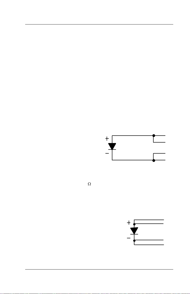
2.4.1.1 Two-Lead Measurement
Sometimes system constraints dictate
two-lead measurement. Connect the
positive terminals (V+ and I+) together
and the negative terminals (V– and I–)
together at the instrument, then run
Two-Lead
Measurements
two leads to the sensor.
Expect some loss in accuracy; the
voltage measured at the voltmeter equals the sum of the sensor voltage and
the voltage drop across the connecting leads. The exact measurement error
depends on sensor sensitivity and variations resulting from changing
temperature. For example, a 10 lead resistance results in a 0.1 mV
voltage error. The resultant temperature error at liquid helium temperature is
only 3 mK, but, because of the lower sensitivity (dV/dT) of the diode at
higher temperatures, it becomes 10 mK at liquid nitrogen temperature.
I+
V+
V–
I–
2.4.1.2 Four-Lead Measurement
All sensors, both two-lead and four-lead devices,
can be measured in a four-lead configuration to
eliminate the effects of lead resistance. The exact
point at which the connecting leads solder to the
Four-Lead
Diode
two-lead sensor normally results in a negligible
temperature uncertainty.
Installation 2-3
I+
V+
V–
I–
Page 16
OMEGA Model CYD201/CYD208 User’s Manual
2.4.2 Connecting Leads To The Sensor
Excessive heat flow through connecting leads to any temperature sensor
may differ the temperature between the active sensing element and the
sample to which the sensor mounts. This reflects as a real temperature
offset between what is measured and the true sample temperature.
Eliminate such temperature errors with proper selection and installation of
connecting leads.
To minimize heat flow through the leads, select leads of small diameter and
low thermal conductivity. Phosphor-bronze or Manganin wire is commonly
used in sizes 32 or 36 AWG. These wires have a fairly low thermal
conductivity, yet electrical resistance is not large enough to create
measurement problems.
Thermally anchor lead wires at several temperatures between room
temperature and cryogenic temperatures to guarantee no heat conduction
through the leads to the sensor.
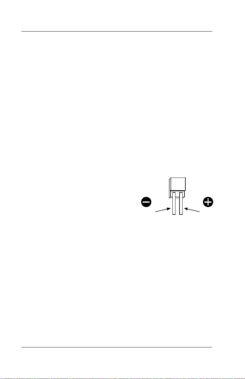
2.4.3 Sensor Mounting
Before installing a diode sensor, identify
which lead is the anode and which is the
cathode. When viewed with the base down
and the leads towards the observer, the
anode is on the right and the cathode is on
the left. The OMEGA CY-7-SD silicon diode
sensor lead configuration is shown to the
right. For other sensors, read accompanying
literature or consult the manufacturer to
Cathode
positively identify sensor leads. Lead identification should remain clear even
after sensor installation. Record the sensor serial number and location.
On the CY-7-SD, the base is the largest flat surface. It is sapphire with gold
metalization over a nickel buffer layer. The base is electrically isolated from
the sensing element and leads; make all thermal contact to the sensor
through the base. A thin braze joint around the sides of the SD package
electrically connect to the sensing element. Avoid contact to the sides with
any electrically conductive material.
When installing the sensor, make sure there are no electrical shorts or
current leakage paths between the leads or between the leads and ground.
If IMI-7031 varnish or epoxy is used, it may soften varnish-type lead
insulations so that high resistance shunts appear between wires if
time for curing is not allowed
Slide Teflon
®
spaghetti tubing over bare leads when the possibility of
.
shorting exists. Avoid putting stress on the device leads and allow for
thermal contractions that occur during cooling which could fracture a solder
joint or lead if installed under tension at room temperature.
DT-470-SD
Diode Sensor Leads
Anode
sufficient
2-4 Installation
Page 17

OMEGA Model CYD201/CYD208 User’s Manual
For temporary mounting in cold temperature applications, apply a thin layer
of Apiezon
®
N Grease between the sensor and sample to enhance thermal
contact under slight pressure. The preferred method for mounting the
CY-7-SD sensor is the OMEGA CO Adapter.
CAUTION: OMEGA will not warranty replace any device damaged by
user-designed clamps or solder mounting.
®
For semi-permanent mountings, use Stycast epoxy instead of Apiezon
Grease.
NOTE:
Do not apply Stycast epoxy over the CY-7-SD package:
N
sensor stress may shift the readings. In all cases, periodically inspect the
sensor mounting to verify good thermal contact to the mounting surface is
maintained.
2.4.4 Measurement Errors Due To AC Noise
Poorly shielded leads or improperly grounded measurement systems can
introduce AC noise into the sensor leads. In diode sensors, the AC noise
shifts the DC voltage measurement due to the diode non-linear
current/voltage characteristics. When this occurs, measured DC voltage is
too low and the corresponding temperature reading is high. The
measurement error can approach several tenths of a kelvin.
this problem exists, perform either procedure below.
1. Place a capacitor across the diode to shunt induced AC currents.
Capacitor size depends on the noise frequency. If noise is related to
power line frequency, use a 10 µF capacitor. If AC-coupled digital noise
is suspected (digital circuits or interfaces), use a 0.1 to 1 µF capacitor. In
either case, if measured DC voltage increases, there is induced noise in
the measurement system.
2. Measure AC voltage across the diode with an AC voltmeter or
oscilloscope. Most voltmeters do not have the frequency response to
measure noise associated with digital circuits or interfaces (which
operate in the MHz range). For a thorough discussion of this potential
problem, and the magnitude of error which may result, request the paper
“Measurement System-Induced Errors In Diode Thermometry,” J.K.
Krause and B.C. Dodrill, Rev. Sci. Instr. 57 (4), 661, April, 1986.
To greatly reduce potential AC noise, connect twisted leads (pairs) between
the measurement instruments and the diode sensors. Use 32 or 36 AWG
OMEGA Duo-Twist™ Cryogenic Wire, which features phosphor bronze wire
twisted at 3.15 twists per centimeter (8 twists per inch). See the OMEGA
Product Catalog or contact OMEGA for further information.
To determine if
Installation 2-5
Page 18
OMEGA Model CYD201/CYD208 User’s Manual
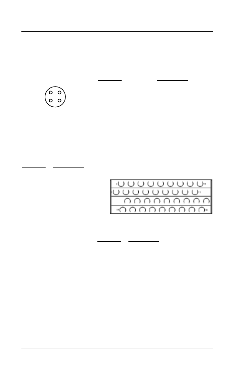
2.5 SENSOR INPUT CONNECTIONS
The Model CYD201 has one rear panel 4-pin sensor input connector
designated J1 INPUT 1. The connector pins, numbered 1 thru 4, are shown
below.
J1 INPUT 1
4
3
Figure 2-1. Model CYD201 Sensor Connector J1 Details
The Model CYD208 has a 36-pin “Miniature-D” style connector designated
J1 INPUTS for inputs 1 thru 8. A Model CYD208-D connector is included to
solder interfacing connections to J1. The pin configuration of the Model
CYD208-D is shown below.
Terminal Description
1 +V - Input 1
2 -V - Input 1
3 +V - Input 2
4 -V - Input 2
5 +V - Input 3
6 -V - Input 3
7 +V - Input 4
8 -V - Input 4
9 +V - Input 5
10 -V - Input 5
11 +V - Input 6
12 -V - Input 6
13 +V - Input 7 25 +I - Input 4
14 -V - Input 7 26 -I - Input 4
15 +V - Input 8 27 +I - Input 5
16 -V - Input 8 28 -I - Input 5
17 Shield 29 +I - Input 6
18 Shield 30 -I - Input 6
19 +I - Input 1 31 +I - Input 7
20 -I - Input 1 32 -I - Input 7
21 +I - Input 2 33 +I - Input 8
22 -I - Input 2 34 -I - Input 8
23 +I - Input 3 35 Shield
24 -I - Input 3 36 Shield
Figure 2-2. Model CYD208-D Sensor Connector Details
1
2
Terminal D
4 + Current Out
1 – Current Out
2 – Voltage Sense
3 + Voltage Sense
CASE Shield
123456789101112131415
1920212223242526272829303132333435
Terminal Description
escription
161718
36
2-6 Installation
Page 19

OMEGA Model CYD201/CYD208 User’s Manual
2.6 SENSOR CURVE DEFINITION
To display accurate temperature, select a response curve that matches the
installed sensor. There are seven standard curves stored within the Model
CYD201/CYD208 numbered 0 through 6 (see Appendix A). Different curves
may be assigned to each channel of the Model CYD208. Find the unit
factory curve configuration inside the front cover of this manual. Curve 6
(CY-7 Curve 10) is the standard curve configuration unless specified
differently upon order.
To determine current curve selection, press and hold
the rear panel SET switch (DIP switch 3). Release
displays the curve number in the display window. The Model CYD208
displays the curve number in the display window and the channel number in
the channel window. To display curves for other channel numbers in the
Model CYD208, press
To change the curve, press
through 6. In the Model CYD208, press
then press
After the new curve selection, turn the SET switch on the rear panel off (0).
The unit returns to normal operation.
UNITS
Table 2-2. Model CYD201/CYD208 Temperature Curves
Curve No. Range (K) Description
CHANNEL
to scroll through the curves.
to scroll through the eight channels.
UNITS
. The instrument scrolls through curves 0
CHANNEL
UNITS
UNITS
to select other channels,
and turn on (1)
key. The CYD201
0
1
2
3
4
5
6
2.7 RACK MOUNTING
The Models CYD201 and CYD208 can install in a standard “size” 1/4 panel
EIA rack space. If you ordered a CYD208-DIN rack mounting adapter, follow
the installation instructions below. See Figure 2-3.
1. Remove front feet on bottom of unit and attach lower rack piece by
threading two of the four screws provided into the front feet holes.
2. Locate the two mounting hole access covers on the top of the unit.
Attach the other rack with the remaining screws.
Installation 2-7
0 – 324.9
0 – 324.9
0 – 324.9
0 – 324.9
0 – 324.9
0 – 324.9
0 – 474.9
DT-500DI-8B
DT-500DI-8A
DT-500DRC-D
DT-500TDC-E1
CTI Curve C
DT-500DI-8C
CY-7 Curve 10
Page 20

OMEGA Model CYD201/CYD208 User’s Manual
0.265 (6.73)
AB
2.50
(63.5)
1.50
(38.10)
Hole Sizes:
A = 0.189 (0.480) Diameter - 4 Places
B = 0.169 (0.429) Diameter - 2 Places
Model CYD201 or CYD208 Front Panel
0.215 (5.46)
A
1.25
(31.75)
ABA
1.44
(35.58)
Figure 2-3. Model CYD208-DIN Rack Mounting
2-8 Installation
C
L
4.18 (106.17)
1.44
(35.58)
Page 21

OMEGA Model CYD201/CYD208 User’s Manual
2.8 INITIAL POWER UP SEQUENCE
The test sequence below occurs at power up.
1. All display segments light.
2. The unit displays “-201-” or “-208-”.
3. The instrument begins normal operation. Units currently selected flash.
Model CYD208s also indicate the current channel selected.
2.9 POWER UP ERRORS
On power up, the CYD201/CYD208 checks internal memory. If a problem
exists, an error message displays on the front panel of the instrument.
Er01
“
” indicates a hardware problem in the instrument memory. This error is
not user-correctable. First perform the procedure in Paragraph 5.3. If
unsuccessful, then call the factory.
Er02
“
” indicates a soft error in the instrument memory. To correct this error,
close dip switch 1 on the rear panel for at least 5 seconds, then open it.
Follow the calibration procedure described in Paragraph 5.3 after an error 2
reset.
“OL” indicates a voltage input overload. This can be caused by an open
sensor or diode sensor wired backwards.
Installation 2-9
Page 22

OMEGA Model CYD201/CYD208 User’s Manual
This Page Intentionally Left Blank
2-10 Installation
Page 23

OMEGA Model CYD201/CYD208 User’s Manual
CHAPTER 3
OPERATION
3.0 GENERAL
This chapter covers the Units Key (Paragraph 3.1), the Channel key
(Paragraph 3.2), Scan Mode (Paragraph 3.3), Setting Dwell Times
(Paragraph 3.4), Alarm Operation (Paragraph 3.5), SoftCal™
Compensations (Paragraph 3.6), Calibration (Paragraph 3.7), Verifying
SoftCal™ Operation (Paragraph 3.8), and Erasing SoftCal™
Compensations (Paragraph 3.9).
KV°C
UNITS
°F
ON
OFF
Figure 3-1. Model CYD201 Front Panel
KV°C
CYD201 THERMOMETER
UNITS
°F
CHANNEL
ON
OFF
Figure 3-2. Model CYD208 Front Panel
3.1 UNITS KEY
UNITS selects different units of measurement. The thermometer reads in
voltage or temperature (°C, °F, or K). Press
various selections.
UNITS
also determines if SoftCal™ is active. Press and hold
3 seconds. If SoftCal™ is not active, -000- appears in the display.
CYD208 THERMOMETER
UNITS
to scroll through the
UNITS
for
Operation 3-1
Page 24

OMEGA Model CYD201/CYD208 User’s Manual
3.2 CHANNEL KEY (Model CYD208 Only)
CHANNEL
scrolls through the eight possible sensor channels.
It also
determines if scan mode is activated. Hold 1 to 2 seconds to toggle scan
mode On or Off. A red light glows in the upper left channel display if scan
mode is active.
3.3 SCAN MODE (Model CYD208 Only)
The thermometer can scan 8 channels or monitor 1 channel. To enable
scan mode, press
CHANNEL
for 1 to 2 seconds to toggle scan mode On or
Off. If a light appears in upper left of channel display window, then scan
mode is On. If the light does not appear, the thermometer is in singlechannel mode. Repeat action to reverse mode.
3.4 SETTING DWELL TIMES (Model CYD208 Only)
Set the time the thermometer pauses on each channel (dwell) for 5, 10, 30,
or 60 seconds. A dwell time of 0 instructs the thermometer to skip that
particular channel. To set the dwell:
1. Hold
2. While still pressing
CHANNEL
for 3 seconds. Do not release.
CHANNEL
, use
UNITS
to select the desired time;
0 (skip), 5, 10, 30, or 60 seconds.
3. Repeat procedure for each desired channel. Default channel dwell is
5 seconds.
3.5 ALARM OPERATION
This section covers Alarm Setpoint (Paragraph 3.5.1), Latched and
Unlatched Alarms (Paragraph 3.5.2.), and the Alarm Fix Function
(Paragraph 3.5.3).
3.5.1 Alarm Setpoint
The alarm setpoint is a temperature which activates the alarm relay. Set it to
warn of temperatures rising above (high alarm) or falling below (low alarm) a
certain point.
NOTE:
Alarm setpoints work for temperatures, not voltage. If in voltage
mode while setting an alarm setpoint, the thermometer defaults to kelvin for
the alarm setpoint.
To display the alarm setpoint, move the SET switch on the rear panel to
position 1. To change the setpoint:
1. Make sure the SET switch is in position 1.
3-2 Operation
Page 25

OMEGA Model CYD201/CYD208 User’s Manual
2. Hold
3. Release UNITS when the desired setpoint displays. For a Model
4. Move the SET switch back to position 0 to enable the alarm. When it
The alarm can be connected to another device which triggers when the
alarm activates. The 3-contact terminal block is present on the rear panel as
J3 ALARM. The alarm contacts are designated 1 COM 2 with 1 representing
the normally open state and 2 representing the normally closed state.
UNITS
it is released and pressed again, the temperature direction reverses. If
the temperature display increases, the alarm is a high setpoint. If the
temperature display decreases, the alarm is a low setpoint.
CYD208, press
window and repeat the steps above to set the alarm for each channel
triggers, an alarm status light appears in the upper left of the
temperature display.
until the desired temperature displays.
CHANNEL
to display the desired channel in the channel
UNITS
is a toggle; if
3.5.2 Latched And Unlatched Alarms
Alarms are either latched or unlatched. The alarm is latched when the
LATCH switch is in position 1: the alarm turns On when triggered by the
alarm setpoint, but will
returns to within the high and low setpoint range. The alarm is unlatched
when the LATCH switch is in position 0; the alarm turns On when triggered
by the alarm setpoint, and automatically turns Off when temperatures return
to within the high and low setpoint range.
not
automatically turn Off when the temperature
3.5.3 Alarm Fix Function (Model CYD208 Only)
Set the FIX switch on the Model CYD208 rear panel to OFF (position 0) to
continuously update the alarm relay, depending on the alarm setpoint and
sensor temperature. If the FIX switch is ON (position 1), the relay updates
only when channel 1 input is active.
3.6 SOFTCAL™ COMPENSATIONS
SoftCal™ is a simple, instrument-configured software calibration that
improves system accuracy over a specified temperature range. It reduces
the error between a CY-7 diode and the Standard Curve 10 used by the
instrument. In short, SoftCal™ generates inexpensive calibrations for CY-7
sensors used with OMEGA temperature controllers and monitors.
Operation 3-3
Page 26

OMEGA Model CYD201/CYD208 User’s Manual
SoftCal™ calibrations are made at three temperature points: liquid helium
(4.2 K), liquid nitrogen (about 77 K), and 305 K. Below is the accuracy* of
the CY-7-SD-13 sensor:
+0.5 K 2 K to <30 K +
+0.25 K 30 K to <60 K +1.0 K 375 K to 475 K
+0.15 K 60 K to <345 K
* These values generally apply to all silicon diode sensors. Only two-point
SoftCal™ calibrations appropriate for CY-7 series Band 11, 11A sensors.
This section covers the SoftCal™ Calibration Procedure (Paragraph 3.6.1),
Verifying SoftCal™ Operation (Paragraph 3.6.2), and Erasing SoftCal™
Compensations (Paragraph 3.6.3).
0.25 K 345 K to <375 K
3.6.1 SoftCal™ Calibration Procedure
1. Turn on thermometer 30 minutes prior to operation.
2. Place the SET switch in position 1.
3. Hold
4. Press
5. Hold
6. Verify sensor stabilization at calibration temperature.
7. Press
8. To enter more than one point, go back to step 5.
9. Return the SET switch to position 0.
UNITS
acts as a toggle. If the display rises, release and press again.
"-SOF-" to indicate the unit is ready to erase the current SoftCal™
calibration. Within 2 seconds press
display changes from "-SOF-" to the current SoftCal™ setting.
setting SoftCal™ for liquid helium, the display reads 4.2 K. If setting for
ice point, the display reads 0 °C.
ready to accept the calibration point. Within 2 seconds, press
enter a new calibration point. (If
the display returns to the alarm temperature). After 15 seconds, the
alarm setpoint temperature displays.
be entered between 1.4 K to 9.9 K. No point may be entered between
10 K and 40 K. Two points may be entered above 40 K.
until 0 kelvin (or equivalent in °C or °F) displays. The key
CAL ENABLE
UNITS
until the sensor temperature displays. For example, if
CAL ENABLE
on rear panel with a pen tip. The display reads
UNITS
again. The temperature
again. "-SOF-" again displays to indicate the unit is
UNITS
is not pressed within 2 seconds,
NOTE:
UNITS
to
One point may
3-4 Operation
Page 27

OMEGA Model CYD201/CYD208 User’s Manual
3.6.2 Verifying SoftCal™ Operation
Check the status of SoftCal™ by holding
SoftCal™ is not in operation, "-000-" displays.
If the first digit of the display is 1, SoftCal™ is set for below 28 K. If either
the second or third digit is 1, SoftCal™ is set for above 28 K.
UNITS
for 2-3 seconds. If
3.6.3 Erasing SoftCal™ Compensations
When SoftCal™ compensations are erased, the thermometer returns to
normal operation.
1. Move the SET switch to position 1.
2. Hold
3. Press
4. Move the SET switch to position 0.
UNITS
display moves in the wrong direction, release and press again.
from 0 to "-SOF-". The alarm setpoint displays after erasing SoftCal™
compensation.
until the front panel displays 0. This key is a toggle. If the
CAL ENABLE
on rear panel using a pen tip. The display changes
Operation 3-5
Page 28

OMEGA Model CYD201/CYD208 User’s Manual
This Page Intentionally Left Blank
3-6 Operation
Page 29

OMEGA Model CYD201/CYD208 User’s Manual
CHAPTER 4
REMOTE OPERATION
4.0 GENERAL
The Model CYD201/CYD208 Digital Thermometer Serial Interface can be
used for both operation and service. This chapter covers the Serial Interface
(Paragraph 4.1) and Serial Interface Commands (Paragraph 4.2).
4.1 SERIAL INTERFACE
The Model CYD201/CYD208 has a serial interface for RS-232C
communications with a host computer. RS-232C is an unbalanced (single
ended), non-terminated line used over short distances (typically 10 feet or
less). The Model CYD201/CYD208 serial interface complies with the
electrical format of the RS-232C Interface Standard. The serial interface
connector is a standard 6 wire RJ-11 modular (telephone) jack.
This section covers Serial Interface Specifications (Table 4-1), Serial
Interface Connections (Paragraph 4.1.1), Serial Interface Hardware
Configuration and Adapters (Figures 4-1 & 4-2), Serial Interface Operation
(Paragraph 4.1.2), and Sample Basic and QuickBasic Programs
(Paragraphs 4.1.3 & 4.1.4 respectively).
Table 4-1. Serial Interface Specifications
Transmission:
Connector:
Timing Format:
Transmission Mode:
Baud Rate:
Bits per Character:
Parity Type:
Data Interface Levels:
Terminator:
Three-Wire
RJ-11 Modular (Telephone) Socket
Asynchronous
Half Duplex
300
1 Start, 7 Data, 1 Parity, 1 Stop
Odd
Transmits/Receives Using EIA Levels
LF (0AH)
4.1.1 Serial Interface Connections
The serial interface connector is a standard 6 wire RJ-11 modular
(telephone) jack. OMEGA Model CYD200-J10 data cables, which maintain
pin 1 polarity, simplify interconnection. OMEGA offers the Model CYD200-D
RJ-11 to DB-25 adapter and Model CYD200-B RJ-11 to DE-9 adapter to
connect to the host computer. See Figure 4-2.
Remote Operation 4-1
Page 30

OMEGA Model CYD201/CYD208 User’s Manual
J2 SERIAL I/O
PIN DESCRIPTION
1
654321
RS-232C In (RxD)
2
RS-232C In (RxD)
3
RS-232C Ground
4
RS-232C Ground
5
RS-232C Out (TxD)
6
RS-232C Out (TxD)
Figure 4-1. Serial I/O (RJ-11) Connector Pin Definitions
Model CYD200-B RJ-11
to DB-2 5 Adapt er
RS-232C
Interface Output
on rear of Model
CYD201 or
CYD208
To Customer Supplied Computer
DB-25 Serial Interface Connector
Mode l CYD200-B
RJ-11 to DE-9 Adapter
DB-9 Serial Interface Connector
To Cust ome r Supp lie d Compute r
Use whichever adapter that
matches your computer
serial interface connector
RJ-11 Cable Assembly
J2 SERIAL I/O
Model CYD200-J10
Figure 4-2. Serial Interface Connections
4-2 Remote Operation
Page 31

OMEGA Model CYD201/CYD208 User’s Manual
4.1.2 Serial Interface Operation
Remotely control all thermometer functions, except SoftCal™
compensations from a computer with communications software and modem.
Located on the rear panel is a RJ-11 modular socket designated J2 SERIAL
I/O for host computer connection. Accessories CYD200-J10 (RS-232C
phone cord) and CYD200-D (RJ-11 to DB-25 adapter), as well as a null
modem adapter may be required to link the serial port of the host computer
directly to the thermometer. When programming a Model CYD201/CYD208
from the serial interface, consider the following:
• Type commands in all CAPS.
• The term
appropriate place in the string of digits.
[term]
•
where they appear on a returning character string from the unit.
• Leading zeros and zeros following a decimal point are not needed in a
command string, but they are sent in response to a query.
• Enter temperature to 0.1 degrees. Greater precision truncates.
Temperature is limited from 0 to 475 K.
• Place no space between commands and the variable being sent.
free field
in examples indicates terminating characters placed by the user or
indicates a floating decimal point placed any
4.1.3 Sample Basic Program
10 OPEN “COM1:300,O,7,1,RS” AS #1 ‘Open COM port
11 PRINT “TYPE ‘QUIT’ TO EXIT” ‘Print QUIT message
12 PRINT ‘Print blank line
20 INPUT “ENTER COMMAND”;A$ ‘Get command to send
21 IF A$ = “QUIT” THEN GOTO 100 ‘Look for QUIT then quit
30 A$ = A$ +CHR$(13)+CHR$(10) ‘Adding CR and LF
40 PRINT #1,A$; ‘Sending command string
45 R = INSTR(A$,”W”) ‘Scan CMD for W/QUERRY
46 IF R = 0 THEN GOTO 90 ‘If not a QUERRY skip PRINT
50 FOR Z = 1 TO 500: NEXT Z ‘Short delay
60 LINE INPUT#1,B$ ‘Read back CYD201/CYD208 response
70 PRINT B$; ‘PRINT instrument response
90 GOTO 11 ‘Jump back to the beginning
100 CLOSE #1 ‘Close COM port
101 END ‘End program
Remote Operation 4-3
Page 32

OMEGA Model CYD201/CYD208 User’s Manual
4.1.4 Sample Quick Basic 4.0 Program
STARTUP: OPEN “COM1:300,O,7,1,RS” FOR RANDOM AS #1
PRINT “TYPE ‘QUIT’ TO EXIT” ‘print ‘QUIT’ message
RESTART: PRINT ‘print blank line
INPUT “ENTER COMMAND”; A$ ‘get command to send
IF A$ = “QUIT” THEN GOTO FINISH ‘check for quit request
A$ = A$ + CHR$(13) + CHR$(10) ‘adding CR and LF
PRINT #1, A$; ‘sending command string
R = INSTR(A$, “W”) ‘scan for W/query
IF R = 0 THEN GOTO REJUMP ‘if not query skip pri nt
FOR Z = 1 TO 500: NEXT Z ‘short delay
LINE INPUT #1, B$ ‘read back CYD201/CYD208 response
PRINT B$; ‘print instrument response
REJUMP: GOTO RESTART ‘jump back to beginning
FINISH: CLOSE #1 ‘close serial port
END ‘end/exit program
4.2 SERIAL INTERFACE COMMAND SUMMARY
Command Function Command Function
F0 Sensor Units for Setpoint Y Scan Dwell Time *
H High Alarm Setpoint YC Scanner Channel Selection *
L Low Alarm Setpoint YH Scan Disable *
R Reset Alarm YS Scan Enable *
WA Switch ID & Alarm Dat a Query WY Scan and Dwell Query *
WS Sensor Reading & Alarm Status Query
* Model CYD208 Only.
‘open the serial port
Below is an explanation of the command list structure.
Command Name
Syntax of user input.
Information returned in
response to query.
Explanation of
returned data.
Brief Description of Function
Alarm Reset.
R
Nothing
Used to reset
R
Input:
Returned:
Remarks:
the alarm.
4-4 Remote Operation
Page 33

OMEGA Model CYD201/CYD208 User’s Manual
F0 Sets Sensor Units for Temperature Display.
Input:
Returned:
Remarks:
F0x
Nothing
Sets sensor units for the temperature display, where
x
= C (Celsius), F (Fahrenheit), K (kelvin), or V (volts).
H Select High Alarm Setpoint Value.
Input:
Returned:
Remarks:
Example: H300[term]
Hxxx.x
Nothing
Sets high alarm setpoint, where
in units specified by F0 command. If the instrument is set for
volts, the alarm defaults to kelvin.
sets a high alarm setpoint of 300 degrees.
xxx.x
= temperature setpoint
L Select Low Alarm Setpoint Value.
Input:
Returned:
Remarks:
Example: L31.2[term]
Lxxx.x
Nothing
Sets low alarm setpoint, where
in units specified by F0 command. If the instrument is set for
volts, the alarm defaults to kelvin.
sets a low alarm setpoint of 31.2 degrees.
xxx.x
= temperature setpoint
R Alarm Reset.
Input:
Returned:
Remarks:
R
Nothing
Resets the alarm.
Y Channel Dwell Time
Input:
Returned:
Remarks:
Example: Y23[term]
Remote Operation 4-5
Yab
Nothing
Sets dwell time for a given channel, where a = channel 1 - 8,
and b = the dwell time parameter as follows:
0
= zero seconds, 1 = 5 seconds, 2 = 10 seconds,
3
= 30 seconds, 4 = 60 seconds
Setting a dwell time of 0 skips the specified channel in the
sequence.
sets the dwell time for channel 2 to 30 seconds.
(Model CYD208 Only)
.
Page 34

OMEGA Model CYD201/CYD208 User’s Manual
YC Channel Scanner Channel
Input:
Returned:
Remarks:
YH End Scanning
Input:
Returned:
Remarks:
YS Begin Scanning
Input:
Returned:
Remarks:
YCx
Nothing
Asynchronously selects a scanner channel for readout
independent of scan feature, where x = channel 1 - 8.
(Model CYD208 Only)
YH
Nothing
Halts input scan at current input channel. Place scanner on
hold when sending any other commands to scanner or
unpredictable results may occur.
(Model CYD208 Only)
YS
Nothing
Starts input scan from current input channel. The instrument
skips every channel with a dwell time of zero.
WA Switch ID and Alarm Data.
Input:
Returned:
Remarks:
WA
For a Model CYD201, returns:
[switch ID],[high or low alarm],[alarm sign],[alarm
setpoint](CR)(LF)
For a Model CYD208, returns:
[switch ID],[high or low alarm],[alarm sign],[alarm
setpoint],[active channel number](CR)(LF)
Provides the switch ID and alarm data. The switch ID
parameter is 0 through 3 for the Model CYD201. It is the sum
of 1 if the alarm set enable is set, plus 2 if relay latching is
desired. The switch ID parameter is 0 through 7 for the Model
CYD208. It is the sum of 1 if the alarm set enable is set, plus
2 if relay latching is desired, plus 4 if the alarm fix is enabled.
High or Low Parameter: H = high alarm, L = low alarm.
(Model CYD208 Only)
.
.
.
4-6 Remote Operation
Page 35

OMEGA Model CYD201/CYD208 User’s Manual
WS Sample Sensor Reading and Alarm Status.
Input:
Returned:
Remarks:
WS
For a Model CYD201, returns:
[sign],[sensor reading],[units],[alarm status] (CR)(LF)
For a Model CYD208, returns:
[current channel],[sign],[sensor reading],[units], [alarm
status](CR)(LF)
Returns the sample sensor reading and alarm status, where
A
= active and I = inactive.
WY Scan Status
Input:
Returned: [scan status],[current channel number],[channel which
Remarks:
WY
caused the alarm state], [channel 1 dwell time],[channel 2
dwell time],...[channel 8 dwell time](CR)(LF)
Returns instrument scan status (scanning or holding),
channel dwell information, and scan position. Scan Status
Parameter: H = holding, S = scanning. Channel Which
Caused the Alarm State Parameter = 1 through 8 or "-" if
alarm is inactive. Channel dwell times are in seconds.
Sending this command with a Model CYD201 returns N to
signify no scanner.
(Model CYD208 Only)
.
Remote Operation 4-7
Page 36

OMEGA Model CYD201/CYD208 User’s Manual
This Page Intentionally Left Blank
4-8 Remote Operation
Page 37

OMEGA Model CYD201/CYD208 User’s Manual
CHAPTER 5
SERVICE
5.0 GENERAL
This chapter covers Model CYD201/CYD208 maintenance: Model CYD201
Rear Panel Connections (Paragraph 5.1), Model CYD208 Rear Panel
Connections (Paragraph 5.2), Error Code Troubleshooting (Paragraph 5.3),
General Maintenance (Paragraph 5.4), Fuse Replacement (Paragraph 5.5),
Line Voltage Selection (Paragraph 5.6), Calibration (Paragraph 5.7), and
Serial Interface Cable and Adapters (Paragraph 5.8).
5.1 MODEL CYD201 REAR PANEL CONNECTIONS
Figure 5-1. Model CYD201 Rear Panel Connections
J1 INPUT 1
J2 SERIAL I/O
computer. May require accessories CYD200-J10 (RJ-11 phone cord) and
CYD200-D (RJ-11 to DB-25 adapter).
J3 ALARM
device. Contact 1 is normally open, contact 2 is normally closed.
Switch
LATCH
indicated by temperature change. When off (position 0), turns alarm off or
on (unlatched).
SET
CAL ENABLE
Calibration. See Paragraph 5.7.2.
I ADJ
Calibration. See Paragraph 5.7.1.
Service 5-1
: Accepts circular 4-pin connector temperature sensor (201-MC).
: RJ-11 jack for serial remote communications to a host
: Relay responds to alarm setpoints and can trigger another
: Not used.
switch: When on (position 1), turns alarm on but not off (latched) as
switch: Used in setting alarm setpoints and recalibration.
(Calibration Enable) pushbutton: Used during A/D Converter
(Current Adjust) trim potentiometer: Used during Current Source
Page 38

OMEGA Model CYD201/CYD208 User’s Manual
5.2 MODEL CYD208 REAR PANEL CONNECTIONS
Figure 5-2. Model CYD208 Rear Panel Connections
J1 INPUTS
adapters. Adapter sits on top of thermometer and accepts up to 8
temperature sensors. Adapter designed for either circular 4-pin (2084) or
stripped wire (2081) sensors.
J2 SERIAL I/O
computer. May require accessories CYD200-J10 (RS-232C phone cord)
and CYD200-D (RJ-11 to DB-25 adapter).
J3 ALARM
device. Contact 1 is normally open, contact 2 is normally closed.
FIX
switch: Switches alarm functions between monitoring all channels
(position 0) or monitoring channel 1 only (position 1).
LATCH
indicated by temperature change. When off (position 0), turns alarm off or
on (unlatched).
SET
CAL ENABLE
Calibration. See Paragraph 5.7.2.
I ADJ
Calibration. See Paragraph 5.7.1.
: Accepts 36-pin “D” style connector (208-MC) and multi-sensor
: RJ-11 jack for serial remote communications to a host
: Relay responds to alarm setpoints and can trigger another
switch: When on (position 1), turns alarm on but not off (latched) as
switch: Used in setting alarm setpoints and recalibration.
(Calibration Enable) pushbutton: Used during A/D Converter
(Current Adjust) trim potentiometer: Used during Current Source
5-2 Service
Page 39

OMEGA Model CYD201/CYD208 User’s Manual
5.3 ERROR CODE TROUBLESHOOTING
On power up, the CYD201/CYD208 checks internal memory. If a problem
exists, an error message displays on the front panel of the instrument.
Er01
indicates a hardware problem in the instrument memory. This error is
not user-correctable.
Er02
indicates a soft error in the instrument memory. To correct this error,
use the following procedure.
1. Power up the unit and allow it to display Er02.
2. Close DIP Switch 1 (top of the switch pressed in). Leave the switch
closed for at least 5 seconds, then open DIP switch 1 (bottom of the
switch pressed in).
3. Verify the Model CYD201/CYD208 display goes through a normal power
up sequence and then displays 499.9 K.
4. The input(s) of the Model CYD201/CYD208 must now be recalibrated
per in procedure in Paragraph 5.7 before the unit can be used.
OL
indicates a voltage input overload. This can be caused by an open
sensor or diode sensor wired backwards.
Before calling the factory about a persistent problem, try the procedure
below:
WARNING: This procedure erases calibration constants stored in NonVolatile RAM. If this procedure is used, recalibrate the instrument.
1. With power turned Off, press and hold
While holding
2. If the Model CYD201/CYD208 displays
procedure in Paragraph 5.7. If
CYD201/CYD208 does not respond, contact OMEGA Service.
CAL ENABLE
, turn instrument power On.
Er01
CAL ENABLE
Er02
still displays or if the Model
, follow the Calibration
on the back panel.
5.4 GENERAL MAINTENANCE
Clean the CYD201/CYD208 periodically to remove dust, grease and other
contaminants. Clean the front and back panels and case with a soft cloth
dampened with a mild detergent and water solution.
NOTE:
Do not use aromatic hydrocarbons or chlorinated solvents to clean
the Model CYD201/CYD208. They may react with the silk screen printing on
the back panel.
Service 5-3
Page 40

OMEGA Model CYD201/CYD208 User’s Manual
5.5 FUSE REPLACEMENT
WARNING: To prevent shock hazard, turn off instrument and
disconnect it from AC line power and all test equipment before
replacing fuse.
1. Turn POWER switch Off and disconnect power cord from unit.
Disconnect all test equipment from unit.
2. Remove all screws from rear panel. Gently pull away rear panel and
remove enclosure cover by sliding it to the back.
3. Remove fuse with a fuse puller. The fuse is located behind the
transformer as shown in Figure 5.3.
4. Replace with a 0.2 A fuse for 110 V (115 VAC) operation or a 0.1 A fuse
for 220 V (230 VAC) operation. Use slow blow fuses.
CAUTION: Replace fuse with the same type and rating as specified by
the line voltage selected.
5. Replace enclosure cover, rear panel, and all screws.
5.6 Line Voltage Configuration
The rear-panel, 3-pronged line power connector permits Model
CYD201/CYD208 operation at either 110 or 220 VAC. The configuration is
indicated on rear panel in the Line Voltage Selection Block. Use the
procedure below to change line voltage.
WARNING: To prevent shock hazard, turn off instrument and
disconnect it from AC line power and all test equipment before
changing line voltage configuration.
1. Turn power switch OFF and disconnect the power cord from the unit.
Disconnect all test equipment from unit.
2. Remove all screws from rear
panel. Gently pull away rear
panel and remove enclosure
cover by sliding it to the back.
3. Modify jumper configuration to
desired line voltage (see
Figure 5-3).
4. Replace fuse to match new
voltage requirements.
5. Replace enclosure cover, rear
panel and all screws.
Figure 5-3
Jumper Configuration
Line Voltage
5-4 Service
Page 41

OMEGA Model CYD201/CYD208 User’s Manual
5.7 RECALIBRATION
OMEGA calibrates and certifies thermometers to original factory
specifications for a reasonable fee. You can recalibrate the thermometer to
original specifications, but OMEGA will not warrant these calibrations.
Recalibration requires a digital voltmeter (DVM) with 4½ digit resolution or
better; and 25 k and 125 k precision resistors with ±0.01% tolerance or
better.
Recalibration involves current source and analog/digital (A/D) converter
calibration. A/D calibration erases all SoftCal™ compensations; perform it
after current source calibration, not before.
5.7.1 Current Source Calibration
1. Allow 30 minute warm-up to achieve rated specifications.
2. Configure 125 k resistor as shown in Figure 5-4. Set Model CYD208 to
channel 1.
3. Connect DVM voltage leads across the resistor and adjust the I ADJ
trimpot (located on rear panel) until DVM displays a voltage of 1.2500
volts ±100 microvolts.
4. Remove DVM and resistor.
Model CYD201 Model CYD208
NOTE:
Do not use a voltmeter for A/D Converter Calibration.
Figure 5-4. Calibration Connections
Service 5-5
Page 42

OMEGA Model CYD201/CYD208 User’s Manual
5.7.2 A/D Converter Calibration
NOTE:
Current source calibration
calibration.
1. Allow 30 minute warm-up to achieve rated specifications.
2. Perform current source calibration.
3. Configure 125 k resistor as shown in Figure 5-4. Set Model 208s to
channel 1.
4. Wait 10 seconds for resistor voltage to settle.
5. Press
CAL ENABLE
, then within 2 seconds press
window shows "-CAL-" for approximately 15 seconds.
6. Repeat procedure with 25 k resistor.
7. For Model CYD208, repeat procedure for other 7 channels. See
Figure 2-2 for pin assignments.
5.8 SERIAL INTERFACE CABLE AND ADAPTERS
1234 56
Figure 5-5. Model CYD200-J10 RJ-11 Cable Assembly Wiring Details
TxD
Gnd
Gnd
RxD
must
be performed
YELLOW
GREEN
RED
BLACK
before
UNITS
A/D converter
. The display
123456
13121110987654321
25 24 23 22 21 20 19 18 17 16 15 14
DB-25 CONNECTOR
= NOT
USED
RxD
654321
Gnd
TxD
RJ-11
RECEPTACLE
Figure 5-6. Model CYD200-D RJ-11 to DB-25 Adapter Wiring Details
5-6 Service
Page 43

OMEGA Model CYD201/CYD208 User’s Manual
54321
9876
DE-9 CONNECTOR
= NOT
USED
RxD
Gnd
TxD
654321
RJ-11
RECEPTACLE
Figure 5-7. Model CYD200-B RJ-11 to DE-9 Adapter Wiring Details
Service 5-7
Page 44

OMEGA Model CYD201/CYD208 User’s Manual
This Page Intentionally Left Blank
5-8 Service
Page 45

OMEGA Model CYD201/CYD208 User’s Manual
CHAPTER 6
OPTIONS AND ACCESSORIES
6.0 GENERAL
This chapter lists options, accessories, sensors, wires, and special
equipment available for the Model CYD201/CYD208.
6.1 ACCESSORIES
MODEL DESCRIPTION OF ACCESSORY
201-MC
208-MC
CYD200-J10
CYD200-D
CYD200-B
2010
2080
2081
2082-1
2082-2
2082-3
2082-4
4-pin Mating Connector for Model CYD201 and Model
2084.
36-pin “D” Style Connector for Model CYD208.
RJ-11 to RJ-11 Phone Cord, 10 feet (3 meters). See
Figure 6-1.
RJ-11 to DB-25 Adapter. Connects RJ-11 to RS-232C
Serial Port on rear of computer. See Figure 6-1.
RJ-11 to DE-9 Adapter. Connects RJ-11 to RS-232C
Serial Port on rear of computer. See Figure 6-1.
Model CYD201 calibration connector.
Model CYD208 calibration connector.
Screw Terminal Adapter. Connects Model CYD208 to
multiple sensor/probe assemblies with stripped ends
and non- permanent wiring. Provision for attachment to
top of thermometer. Fitted with “D” type mating
connector.
Stainless steel Sensor Probe with 6-foot (1.83 m) cable
with 4 stripped ends. 4-inch (10 cm) long by
1
/8 inch
(3.2 mm) diameter probe.
Stainless steel Sensor Probe with 6-foot (1.83 m) cable
with 4-pin 201-MC mating connector. 4-inch (10 cm)
long by
Stainless steel Sensor Probe with 12-foot (3.7 m) cable
with 4 stripped ends. 6-inch (15 cm) long by
1
/8 inch (3.2 mm) diameter probe.
1
/8 inch
(3.2 mm) diameter probe.
Stainless steel Sensor Probe with 12-foot (3.7 m) cable
with 4-pin 201-MC mating connector. 6-inch (15 cm)
long by
1
/8 inch (3.2 mm) diameter probe.
Options and Accessories 6-1
Page 46

OMEGA Model CYD201/CYD208 User’s Manual
ACCESSORIES
(continued)
MODEL DESCRIPTION OF ACCESSORY
Sensor Probe. 12-foot (3.7 m) cable with CY-7-SD-13
sensor in CY mounting adapter, stripped ends. Tempera-
2083-1
ture limit: 325 K (52 °C). Diode sensor epoxied (Stycast)
into center of 0.564 inch (1.43 cm) diameter by 0.20 inch
(5 mm) thick copper disk. 30 AWG copper leads anchored
to disk. Mass (excluding leads): 4.3 grams.
Sensor Probe. 12-foot (3.7 m) cable with CY-7-SD-13
sensor in CY mounting adapter, with 4-pin CYD201-MC
mating connector. Temperature limit: 325 K (52 °C). Diode
2083-2
sensor epoxied (Stycast) into center of 0.564 inch (1.43
cm) diameter by 0.20 inch (5 mm) thick copper disk. 30
AWG copper leads anchored to disk. Mass (excluding
leads): 4.3 grams.
Multi-Connector Adapter. Required with Model CYD208
2084
when using multiple probe/cable assemblies and Model
201-MC mating connectors.
CYD208
-DIN
Mounting Adapter for Rack Installation. For installation in
¼
a
panel EIA rack space. See Figure 2-3.
6.2 MODEL CYD201/CYD208 WIRES
LSCI P/N DESCRIPTION OF CABLE
9001-005
Quad-Twist™ Cryogenic Wire.
phosphor-bronze wire, 36 AWG, 0.127 mm (0.005 inch)
Two twisted pairs,
diameter.
9001-006
Duo-Twist™ Cryogenic Wire.
phosphor-bronze wire, 36 AWG, 0.127 mm (0.005 inch)
Single twisted pair,
diameter.
9001-007
9001-008
—
Quad-Lead™ Cryogenic Wire
flat, 32 AWG, 0.203 mm (0.008 inch) diameter.
Quad-Lead™ Cryogenic Wire
flat, 32 AWG, 0.127 mm (0.005 inch) diameter.
Any quality dual shield twisted pair wire for dewar to
Model CYD201/CYD208 connector.
. Phosphor-bronze wire,
. Phosphor-bronze wire,
6-2 Options and Accessories
Page 47

OMEGA Model CYD201/CYD208 User’s Manual
6.3 MODEL CYD201/CYD208 SENSORS
SENSOR NO. DESCRIPTION OF SENSOR
The smallest silicon diode Temperature Sensor
Series DT-420
available. Installs on flat surfaces. Same silicon
chip as Series CY-7 and DT-471.
Silicon Diode Miniature Temperature Sensor. Same
Series DT-450
silicon chip as CY-7 designed to install in recesses
as small as 1.6 mm dia. by 3.2 mm deep.
Silicon Diode Temperature Sensor. Repeatable,
Series CY-7
interchangeable, accurate, wide range, customized
for cryogenics.
An economical version of the CY-7 for applications
Series DT-471
where temperature measurements below 10 K are
not required.
Model CYD200- B RJ-11
to DB-2 5 Adapter
RS-232C
Interface Output
on rear of Model
CYD201 or
CYD208
To Customer Supplied Computer
DB-25 Serial Interface Connector
Model CYD200-B
RJ-11 to DE-9 Adapter
DB-9 Serial Interface Connector
To Customer Supplied Com puter
Use whichever adapter that
matches your computer
serial interface connector
Model CYD200-J10
RJ-11 Cable Assembly
J2 SERIAL I/O
Figure 6-1. Serial Interface Adapters
Options and Accessories 6-3
Page 48

OMEGA Model CYD201/CYD208 User’s Manual
This Page Intentionally Left Blank
6-4 Options and Accessories
Page 49

OMEGA Model CYD201/CYD208 User’s Manual
APPENDIX A
CURVE TABLES
A1.0 GENERAL
The following curve tables apply to the Model CYD201/CYD208: Curve 0 DT-500DI-8B (Table A-1), Curve 1 - DT-500DI-8A (Table A-2), Curve 2 DT-500DRC-D (Table A-3), Curve 3 - DT-500DRC-E1 (Table A-4), Curve 4 CTI Curve C (Table A-5), Curve 5 - DT-500DI-8C (Table A-6), and Curve 6 CY-7 Curve 10 (Table A-7).
Table A-1. Curve 0: DT-500DI-8B Voltage-Temp. Characteristics
Temp. PROM
BP # (K) Voltage
Temp. PROM
BP # (K) Voltage
Temp. PROM
BP # (K) Voltage
29 4.0 2.41773
4.2 2.40475
4.4 2.39217
4.6 2.37946
4.8 2.36668
5.0 2.35378
5.5 2.32126
6.0 2.28869
6.5 2.25643
7.0 2.22480
7.5 2.19395
28 8.0 2.16053
8.5 2.13552
9.0 2.10809
9.5 2.08197
10.0 2.05687
11.0 2.00852
12.0 1.96003
13.0 1.90579
27 14.0 1.85614
15.0 1.80479
26 16.0 1.74703
17.0 1.67479
18.0 1.60665
19.0 1.53675
20.0 1.46370
21.0 1.38832
25 22.0 1.31868
23.0 1.26476
24 24.0 1.21712
23 25.0 1.17857
22 26.0 1.15106
21 27.0 1.13317
20 28.0 1.12169
19 29.0 1.11353
18 30.0 1.10729
17 32.0 1.09810
16 34.0 1.09125
15 36.0 1.08547
38.0 1.08038
14 40.0 1.07549
45.0 1.06400
13 50.0 1.05273
55.0 1.04123
12 60.0 1.02954
65.0 1.01748
11 70.0 1.00528
75.0 0.99263
77.4 0.98666
80.0 0.97988
10 85.0 0.96711
90.0 0.95397
95.0 0.94086
100.0 0.92767
105.0 0.91443
9 110.0 0.90124
115.0 0.88776
120.0 0.87434
125.0 0.86087
130.0 0.84735
135.0 0.83377
8 140.0 0.82032
145.0 0.80647
150.0 0.79274
155.0 0.77896
160.0 0.76513
165.0 0.75125
170.0 0.73733
7 175.0 0.72353
180.0 0.70936
185.0 0.69532
190.0 0.68125
195.0 0.66713
200.0 0.65302
205.0 0.63889
210.0 0.62475
215.0 0.61066
6 220.0 0.59646
225.0 0.58262
230.0 0.56877
235.0 0.55504
5 240.0 0.54136
245.0 0.52801
250.0 0.51469
4 255.0 0.50155
260.0 0.48815
265.0 0.47486
270.0 0.46148
275.0 0.44800
3 280.0 0.43451
285.0 0.42064
290.0 0.40675
295.0 0.39274
2 300.0 0.37875
305.0 0.36436
310.0 0.35002
315.0 0.33559
320.0 0.32109
325.0 0.30656
1 330.0 0.29222
Appendix A A-1
Page 50

OMEGA Model CYD201/CYD208 User’s Manual
Table A-2. Curve 1: DT-500DI-8A Voltage-Temp. Characteristics
Temp. PROM
BP # (K) Voltage
Temp. PROM
BP # (K) Voltage
Temp. PROM
BP # (K) Voltage
30 4.0 2.46386
4.2 2.44821
4.4 2.43188
4.6 2.41500
4.8 2.39781
29 5.0 2.37578
5.5 2.33823
6.0 2.29906
6.5 2.26440
28 7.0 2.23248
7.5 2.20480
8.0 2.17716
8.5 2.14994
27 9.0 2.12245
9.5 2.10065
10.0 2.07844
11.0 2.03712
12.0 1.99736
13.0 1.95641
26 14.0 1.91202
15.0 1.85236
16.0 1.79177
17.0 1.73193
25 18.0 1.66870
19.0 1.59215
20.0 1.51169
21.0 1.43234
24 22.0 1.34993
23 23.0 1.28434
22 24.0 1.23212
21 25.0 1.18995
20 26.0 1.16027
19 27.0 1.14015
18 28.0 1.12689
17 29.0 1.11741
16 30.0 1.11007
15 32.0 1.09942
14 34.0 1.09178
13 36.0 1.08559
12 38.0 1.07992
40.0 1.07502
45.0 1.06307
50.0 1.05136
55.0 1.03951
11 60.0 1.02744
65.0 1.01475
70.0 1.00193
10 75.0 0.98892
77.4 0.98264
80.0 0.97557
85.0 0.96216
90.0 0.94877
9 95.0 0.93535
100.0 0.92166
105.0 0.90798
110.0 0.89426
115.0 0.88052
120.0 0.86676
125.0 0.85298
8 130.0 0.83936
135.0 0.82531
140.0 0.81142
145.0 0.79749
150.0 0.78351
155.0 0.76950
160.0 0.75544
165.0 0.74135
7 170.0 0.72739
175.0 0.71308
180.0 0.69891
185.0 0.68469
190.0 0.67043
195.0 0.65615
200.0 0.64185
205.0 0.62754
210.0 0.61333
6 215.0 0.59901
220.0 0.58502
225.0 0.57099
230.0 0.55715
5 235.0 0.54327
240.0 0.52983
245.0 0.51639
250.0 0.50302
255.0 0.48965
260.0 0.47625
4 265.0 0.46292
270.0 0.44925
275.0 0.43559
280.0 0.42178
3 285.0 0.40797
290.0 0.39375
295.0 0.37951
300.0 0.36515
2 305.0 0.35078
310.0 0.33599
315.0 0.32121
320.0 0.30643
325.0 0.29159
1 330.0 0.27665
Page 51

OMEGA Model CYD201/CYD208 User’s Manual
Table A-3. Curve 2: DT-500DRC-D Voltage-Temp. Characteristics
Temp. PROM
BP # (K) Voltage
Temp. PROM
BP # (K) Voltage
Temp. PROM
BP # (K) Voltage
1.4 2.5984
1.5 2.5958
1.6 2.5932
1.7 2.5906
1.8 2.5880
1.9 2.5854
30 2.0 2.5828
2.2 2.5735
2.4 2.5643
2.6 2.5551
2.8 2.5458
29 3.0 2.5366
3.2 2.5226
3.4 2.5086
3.6 2.4946
3.8 2.4807
4.0 2.4667
4.2 2.4527
4.4 2.4387
4.6 2.4247
4.8 2.4108
5.0 2.3968
5.5 2.3618
6.0 2.3269
6.5 2.2919
7.0 2.2570
7.5 2.2220
8.0 2.1871
8.5 2.1521
28 9.0 2.1172
9.5 2.0909
10.0 2.0646
11.5 2.0119
12.0 1.9592
27 13.0 1.9066
14.0 1.8338
26 15.0 1.7610
16.0 1.6984
25 17.0 1.6359
18.0 1.5646
19.0 1.4932
20.0 1.4219
24 21.0 1.3505
22.0 1.3006
23 23.0 1.2507
24.0 1.2114
22 25.0 1.1720
21 26.0 1.1486
20 27.0 1.1308
19 28.0 1.1190
18 29.0 1.1116
17 30.0 1.1058
16 32.0 1.0970
15 34.0 1.0902
36.0 1.0850
38.0 1.0798
14 40.0 1.0746
45.0 1.0633
50.0 1.0520
13 55.0 1.0407
60.0 1.0287
65.0 1.0166
12 70.0 1.0046
75.0 0.99172
80.0 0.97890
85.0 0.96609
11 90.0 0.95327
95.0 0.93987
100.0 0.92647
105.0 0.91307
110.0 0.89966
115.0 0.88626
120.0 0.87286
125.0 0.85946
10 130.0 0.84606
135.0 0.83228
140.0 0.81850
145.0 0.80472
150.0 0.79094
155.0 0.77716
160.0 0.76338
165.0 0.74961
9 170.0 0.73582
175.0 0.72170
180.0 0.70757
185.0 0.69344
190.0 0.67931
195.0 0.65518
200.0 0.65105
205.0 0.63693
210.0 0.62280
215.0 0.60867
8 220.0 0.59455
225.0 0.58080
230.0 0.56707
235.0 0.55334
7 240.0 0.53960
245.0 0.52649
250.0 0.51337
255.0 0.50026
260.0 0.48714
6 265.0 0.47403
270.0 0.46057
275.0 0.44711
280.0 0.43365
5 285.0 0.42019
290.0 0.40613
295.0 0.39208
300.0 0.37802
4 305.0 0.36397
310.0 0.34940
315.0 0.33482
320.0 0.32025
325.0 0.30568
330.0 0.29111
335.0 0.27654
340.0 0.26197
3 345.0 0.24739
350.0 0.23325
355.0 0.21911
360.0 0.20497
2 365.0 0.19083
370.0 0.17774
375.0 0.16464
1 380.0 0.15155
Appendix A A-3
Page 52

OMEGA Model CYD201/CYD208 User’s Manual
Table A-4. Curve 3: DT-500DRC-E1 Voltage-Temp. Characteristics
Temp. PROM
BP # (K) Voltage
Temp. PROM
BP # (K) Voltage
Temp. PROM
BP # (K) Voltage
30 1.4 2.6591
1.5 2.6567
1.6 2.6542
1.7 2.6518
1.8 2.6494
1.9 2.6470
29 2.0 2.6446
2.2 2.6355
2.4 2.6265
2.6 2.6175
2.8 2.6084
28 3.0 2.5994
3.2 2.5868
3.4 2.5742
3.6 2.5616
3.8 2.5490
27 4.0 2.5364
4.2 2.5221
4.4 2.5077
4.6 2.4934
4.8 2.4791
5.0 2.4648
5.5 2.4290
6.0 2.3932
6.5 2.3574
7.0 2.3216
7.5 2.2858
8.0 2.2500
8.5 2.2142
26 9.0 2.1784
9.5 2.1516
10.0 2.1247
11.0 2.0708
12.0 2.0170
25 13.0 1.9632
14.0 1.9011
15.0 1.8390
16.0 1.7769
17.0 1.7148
18.0 1.6527
19.0 1.5724
20.0 1.4922
21.0 1.4120
22.0 1.3317
23.0 1.2837
24.0 1.2357
21 25.0 1.1877
20 26.0 1.1559
19 27.0 1.1365
18 28.0 1.1239
17 29.0 1.1150
16 30.0 1.1080
15 32.0 1.0981
14 34.0 1.0909
13 36.0 1.0848
38.0 1.0797
12 40.0 1.0746
45.0 1.0630
50.0 1.0515
55.0 1.0399
11 60.0 1.0284
65.0 1.0159
70.0 1.0035
75.0 0.9911
77.35 0.9849
80.0 0.9780
85.0 0.9649
90.0 0.9518
95.0 0.9388
9 100.0 0.9257
105.0 0.9122
110.0 0.8988
115.0 0.8853
120.0 0.8718
125.0 0.8584
8 130.0 0.8449
135.0 0.8311
140.0 0.8173
145.0 0.8035
150.0 0.7896
155.0 0.7758
160.0 0.7620
165.0 0.7482
7 170.0 0.7344
175.0 0.7202
180.0 0.7060
185.0 0.6918
190.0 0.6777
195.0 0.6635
200.0 0.6493
205.0 0.6351
210.0 0.6210
215.0 0.6068
6 220.0 0.5926
225.0 0.5789
230.0 0.5651
235.0 0.5514
240.0 0.5377
245.0 0.5246
250.0 0.5115
255.0 0.4984
260.0 0.4853
4 265.0 0.4722
270.0 0.4588
275.0 0.4454
280.0 0.4320
3 285.0 0.4186
290.0 0.4045
295.0 0.3904
300.0 0.3763
2 305.0 0.3622
310.0 0.3476
315.0 0.3330
320.0 0.3184
325.0 0.3038
1 330.0 0.2893
Page 53

OMEGA Model CYD201/CYD208 User’s Manual
Table A-5. Curve 4: CTI Diode Voltage-Temp. Characteristics
Temp. PROM
BP # (K) Voltage
Temp. PROM
BP # (K) Voltage
Temp. PROM
BP # (K) Voltage
29 10.0 1.4000
28 11.0 1.3850
27 12.0 1.3656
13.0 1.3400
26 14.0 1.3161
15.0 1.2750
16.0 1.2350
17.0 1.1910
25 18.0 1.1500
24 19.0 1.1290
23 20.0 1.1162
21.0 1.1135
22.0 1.1109
23.0 1.1084
24.0 1.1058
25.0 1.1033
26.0 1.1007
27.0 1.0981
28.0 1.0955
29.0 1.0929
30.0 1.0903
32.0 1.0851
34.0 1.0799
22 36.0 1.0747
38.0 1.0693
40.0 1.0640
45.0 1.0505
50.0 1.0370
55.0 1.0235
21 60.0 1.0100
20 65.0 0.9958
70.0 0.9822
75.0 0.9690
19 77.4 0.9626
80.0 0.9560
18 85.0 0.9440
17 90.0 0.9314
16 95.0 0.9184
15 100.0 0.9049
105.0 0.8907
14 110.0 0.8769
13 115.0 0.8625
120.0 0.8500
12 125.0 0.8376
11 130.0 0.8245
135.0 0.8109
10 140.0 0.7971
145.0 0.7828
150.0 0.7685
155.0 0.7543
160.0 0.7400
9 165.0 0.7255
170.0 0.7114
175.0 0.6972
180.0 0.6830
185.0 0.6690
190.0 0.6545
8 195.0 0.6408
200.0 0.6270
205.0 0.6133
210.0 0.5995
215.0 0.5858
220.0 0.5720
225.0 0.5583
230.0 0.5445
235.0 0.5308
240.0 0.5170
245.0 0.5032
7 250.0 0.4896
255.0 0.4757
260.0 0.4620
265.0 0.4481
6 270.0 0.4341
275.0 0.4197
5 280.0 0.4050
4 285.0 0.3911
290.0 0.3775
3 295.0 0.3640
300.0 0.3510
2 305.0 0.3382
310.0 0.3243
315.0 0.3106
1 320.0 0.2968
Appendix A A-5
Page 54

OMEGA Model CYD201/CYD208 User’s Manual
Table A-6. Curve 5: DT-500DI-8C Voltage-Temp. Characteristics
Temp. PROM
BP # (K) Voltage
Temp. PROM
BP # (K) Voltage
Temp. PROM
BP # (K) Voltage
29 4.0 2.6187
4.2 2.6074
4.4 2.5956
4.6 2.5834
4.8 2.5709
5.0 2.5580
28 5.2 2.5484
5.4 2.5312
5.6 2.5173
5.8 2.5033
6.0 2.4890
6.5 2.4524
7.0 2.4151
7.5 2.3773
8.0 2.3394
27 8.5 2.2976
9.0 2.2643
9.5 2.2277
10.0 2.1919
10.5 2.1566
11.0 2.1221
11.5 2.0881
12.0 2.0545
12.5 2.0211
13.0 1.9875
13.5 1.9537
14.0 1.9193
14.5 1.8843
15.0 1.8480
15.5 1.8110
16.0 1.7748
26 16.5 1.7441
17.0 1.7047
17.5 1.6702
18.0 1.6361
18.5 1.6022
19.0 1.5676
19.5 1.5316
20.0 1.4950
21.0 1.4218
25 22.0 1.3461
24 23.0 1.2840
23 24.0 1.2317
22 25.0 1.1900
21 26.0 1.1602
20 27.0 1.1402
19 28.0 1.1269
18 29.0 1.1173
17 30.0 1.1100
16 31.0 1.1039
32.0 1.0991
15 33.0 1.0949
34.0 1.0913
14 35.0 1.0879
36.0 1.0850
37.0 1.0822
13 38.0 1.0795
39.0 1.0770
40.0 1.0746
42.0 1.0697
12 44.0 1.0649
46.0 1.0603
48.0 1.0558
50.0 1.0512
52.0 1.0467
54.0 1.0421
56.0 1.0376
58.0 1.0330
11 60.0 1.0285
65.0 1.0168
70.0 1.0049
10 75.0 0.9930
77.4 0.9870
80.0 0.9805
85.0 0.9680
90.0 0.9553
9 95.0 0.9427
100.0 0.9297
105.0 0.9168
110.0 0.9038
115.0 0.8907
8 120.0 0.8777
125.0 0.8643
130.0 0.8510
135.0 0.8377
140.0 0.8243
145.0 0.8108
7 150.0 0.7974
155.0 0.7837
160.0 0.7701
165.0 0.7564
170.0 0.7427
175.0 0.7289
6 180.0 0.7152
185.0 0.7013
190.0 0.6874
195.0 0.6734
200.0 0.6595
205.0 0.6455
210.0 0.6315
215.0 0.6176
5 220.0 0.6036
225.0 0.5898
230.0 0.5761
235.0 0.5625
4 240.0 0.5490
245.0 0.5358
250.0 0.5226
255.0 0.4096
260.0 0.4966
265.0 0.4836
270.0 0.4705
275.0 0.4574
3 280.0 0.4442
285.0 0.4307
290.0 0.4171
295.0 0.4035
2 300.0 0.3898
305.0 0.3758
310.0 0.3618
315.0 0.3477
320.0 0.3336
325.0 0.3194
1 330.0 0.3054
Page 55

OMEGA Model CYD201/CYD208 User’s Manual
Table A-7. Curve 6: CY-7 Voltage-Temp. Characteristics
Temp. PROM
BP # (K) Voltage
Temp. PROM
BP # (K) Voltage
BP # (K) Voltage
Temp. PROM
29 1.4 1.69808
1.5 1.69674
1.6 1.69521
1.7 1.69355
1.8 1.69177
1.9 1.68987
28 2.0 1.68912
2.1 1.68574
2.2 1.68352
2.3 1.68121
2.4 1.67880
2.5 1.67632
2.6 1.67376
2.7 1.67114
2.8 1.66845
2.9 1.66571
3.0 1.66292
3.1 1.66009
3.2 1.65721
3.3 1.65430
3.4 1.65134
3.5 1.64833
3.6 1.64529
3.7 1.64219
27 3.8 1.64112
3.9 1.63587
4.0 1.63263
4.2 1.62602
4.4 1.61920
4.6 1.61220
4.8 1.60506
5.0 1.59782
5.2 1.59047
5.4 1.58303
5.6 1.57551
5.8 1.56792
6.0 1.56027
6.5 1.54097
7.0 1.52166
7.5 1.50272
8.0 1.48443
8.5 1.46700
26 9.0 1.44850
9.5 1.43488
10.0 1.42013
10.5 1.40615
11.0 1.39287
11.5 1.38021
25 12.0 1.36687
12.5 1.35647
13.0 1.34530
13.5 1.33453
14.0 1.32412
14.5 1.31403
15.0 1.30422
24 15.5 1.29340
16.0 1.28527
16.5 1.27607
17.0 1.26702
17.5 1.25810
18.0 1.24928
18.5 1.24053
19.0 1.23184
19.5 1.22314
23 20.0 1.21555
21.0 1.19645
22.0 1.17705
23.0 1.15558
22 24.0 1.13598
21 25.0 1.12463
20 26.0 1.11896
19 27.0 1.11517
18 28.0 1.11202
29.0 1.10945
30.0 1.10702
17 31.0 1.10465
32.0 1.10263
33.0 1.10060
34.0 1.09864
35.0 1.09675
16 36.0 1.09477
37.0 1.09309
38.0 1.09131
39.0 1.08955
40.0 1.08781
42.0 1.08436
15 44.0 1.08105
46.0 1.07748
48.0 1.07402
50.0 1.07053
52.0 1.06700
54.0 1.06346
56.0 1.05988
58.0 1.05629
14 60.0 1.05277
65.0 1.04353
70.0 1.03425
75.0 1.02482
13 77.4 1.02044
80.0 1.01525
85.0 1.00552
90.0 0.99565
12 95.0 0.98574
100.0 0.97550
105.0 0.96524
110.0 0.95487
11 115.0 0.94455
120.0 0.93383
125.0 0.92317
130.0 0.91243
135.0 0.90161
10 140.0 0.89082
145.0 0.87976
150.0 0.86873
155.0 0.85764
160.0 0.84650
9 165.0 0.83541
170.0 0.82404
175.0 0.81274
180.0 0.80138
185.0 0.78999
190.0 0.77855
8 195.0 0.76717
200.0 0.75554
205.0 0.74398
210.0 0.73238
215.0 0.72075
220.0 0.70908
225.0 0.69737
7 230.0 0.68580
235.0 0.67387
240.0 0.66208
245.0 0.65026
250.0 0.63841
255.0 0.62654
260.0 0.61465
265.0 0.60273
270.0 0.59080
275.0 0.57886
6 280.0 0.56707
285.0 0.55492
290.0 0.54294
295.0 0.53093
300.0 0.51892
Appendix A A-7
Page 56

OMEGA Model CYD201/CYD208 User’s Manual
Table A-7. Curve 6: CY-7 Voltage-Temp. Characteristics
Temp. PROM
BP # (K) Voltage
305.0 0.50689
310.0 0.49484
315.0 0.48278
320.0 0.47069
325.0 0.45858
330.0 0.44647
335.0 0.43435
5 340.0 0.42238
345.0 0.41003
350.0 0.39783
355.0 0.38561
360.0 0.37337
Temp. PROM
BP # (K) Voltage
365.0 0.36110
370.0 0.34881
375.0 0.33650
380.0 0.32416
385.0 0.31180
4 390.0 0.29958
395.0 0.28700
400.0 0.27456
405.0 0.26211
410.0 0.24963
415.0 0.23714
420.0 0.22463
Temp. PROM
BP # (K) Voltage
425.0 0.21212
430.0 0.19961
3 435.0 0.18696
440.0 0.17464
445.0 0.16221
450.0 0.14985
455.0 0.13759
2 460.0 0.12536
465.0 0.11356
470.0 0.10191
1 475.0 0.09032
(Continued)
Page 57

NOTES
Page 58

NOTES
Page 59

TEMPERATURE
Thermocouple, RTD & Thermistor Probes & Assemblies
Connector Systems and Panels
Wire: Thermocouple, RTD, and Thermistor
Calibrators and Ice Point References
Recorders, Controllers, and Process Monitors
Data Acquisition Modules and Data Loggers
Computer Sensor Interface
PRESSURE/STRAIN
Transducers
Strain Gauges
Load Cells
Pressure Gauges
Instrumentation
FLOW
Rotameters
Flowmeter Systems
Air Velocity Indicators
Turbine/Paddlewheel Systems
Vortex Meters and Flow Computers
pH
Electrodes
Benchtop/Laboratory Meters
Controllers
Calibrators/Simulators
Transmitters
Page 60

 Loading...