

Page 1
HIGH PERFORMANCE
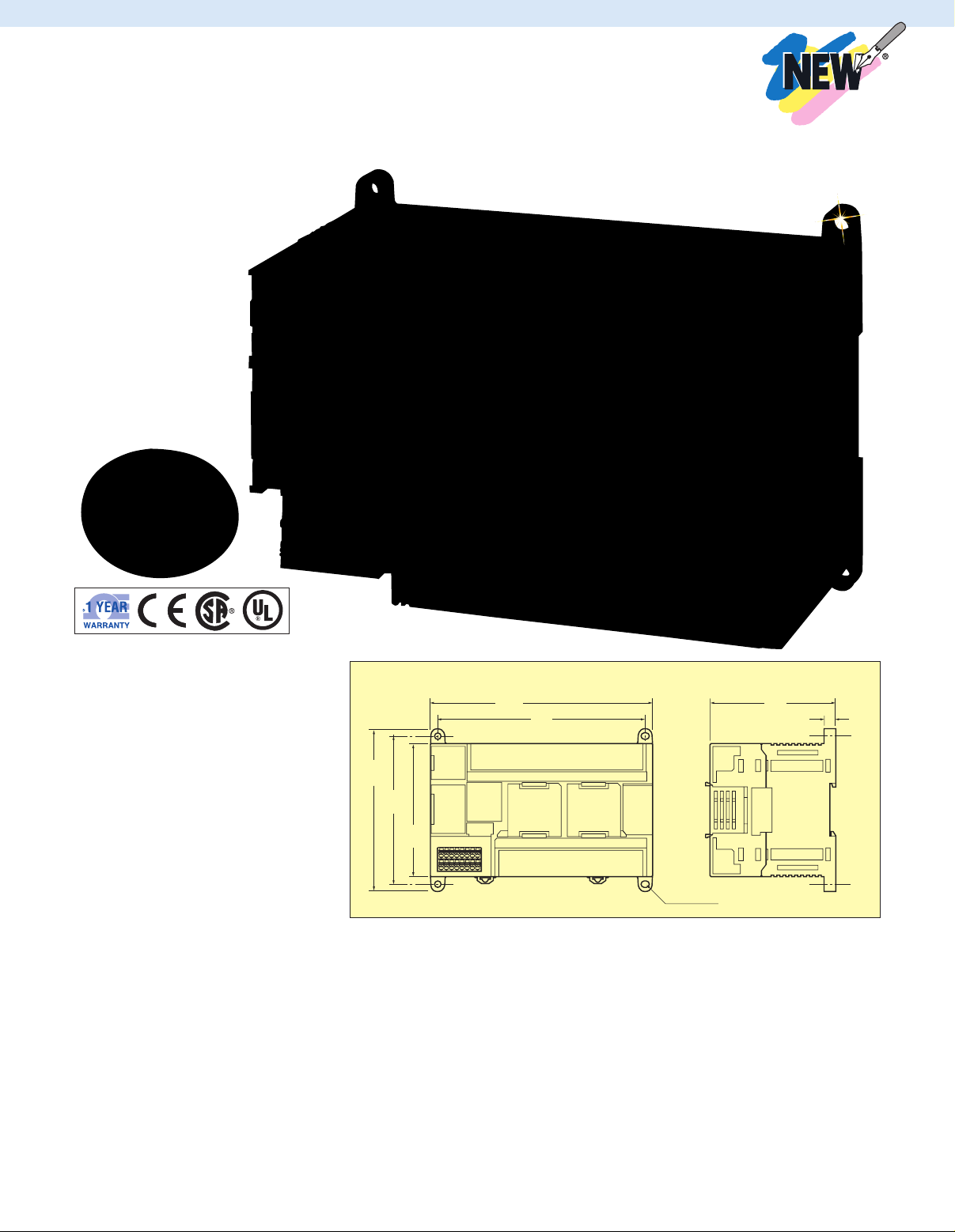
Four, 4.5 (0.18) dia.
90
(3.54)
100
(3.94)
110
(4.33)
140
(5.51)
150
(5.90)
8
(0.31)
85
(3.35)
PROGRAMMABLE LOGIC
CONTROLLERS (PLCs)
CP1H-Y20DT-D, $1080,
with CP1W-CIF01, $85 and
CP1W-CIF11, $85, shown
smaller than actual size.
CP1H
Starts at
$
1060
l Up to 24 Digital Inputs,
16 Digital/Relay Outputs
l Expandable to 320 I/O with
Expansion Modules
l Powerful Instruction Set
l 20K Program Steps
(32K Words Data Memory)
l Remote I/O Modules for Analog
I/O, Digital I/O, Thermocouples
and RTDs
l xA Model Provides Analog I/O
(4 Inputs, 2 Outputs)
l Y Model Provides 1 MHz
Counters and Pulse Outputs
The CP1H Series is the ultimate highperformance all-in-one package-type PLC.
A wide variety of built-in functions expand
application capabilities and shorten the
design time required for the growing number
and increasing complexity of ladder
programs. Three types of CPU units are
available to meet applications requiring
advanced functionality: The CP1H-x with
pulse outputs for 4 axes, the CP1H-Y with
1 MHz pulse I/O, and the CP1H-xA with
built-in analog I/O.
CP1H CPU Units
With high-speed encoder inputs and pulse
outputs, CP1H CPUs are ideal for positioning
and speed control. The built-in analog I/O of
the CP1H-xA units plus advanced PID control
with auto-tuning also make them ideal for
continuous process control applications.
Equipped with a USB interface as standard
for programming and monitoring, the new
CPUs allow up to two serial ports to be
plugged in for communication with HMI or
field devices. And, of course, they provide
‘Smart Platform’ communication routing
A-1
Dimensions: mm (in)
over multiple network layers.
Using Cx-One, programs can be created that
enable the user to build, configure and
program networks, PLCs, HMIs, motioncontrol systems, drives, temperature
controllers and sensors.
The CP1H CPU series has the same
architecture as the CS/CJ PLC series, which
means programs are compatible for memory
allocations and instructions and support
Function Blocks and Structured Text in
addition to Ladder Logic.
Page 2

CPU UNIT SPECIFICATIONS
ITEMS CP1H-xxx-A CP1H-xxx-D
POWER SUPPLY 100 to 240 Vac 50/60 Hz 24 Vdc
OPERATING VOLTAGE RANGE 85 to 264 Vac 21.6 to 26.4 Vdc
POWER CONSUMPTION 100 VA max 50 W max
INRUSH CURRENT 100 to 120 Vac inputs: 20 A max, 8 ms max 30 A max 20 ms max
EXTERNAL POWER SUPPLY None 300 mA at 24 Vdc
INSULATION RESISTANCE 20 MΩ min (at 500 Vdc) between the 20 MΩ min (at 500 Vdc) between the
DIELECTRIC STRENGTH 2300 Vac at 50/60 Hz for 1 min between 1000 Vac at 50/60 Hz for 1 min between
NOISE IMMUNITY Conforming to IEC 61000-4-4. 2 kV (power supply line)
VIBRATION RESISTANCE 10 to 57 Hz, 0.075-mm amplitude, 57 to 150 Hz, acceleration: 9.8 m/s
SHOCK RESISTANCE 147 m/s
AMBIENT OPERATING 0 to 55°C (32 to 131ºF)
TEMPERATURE
AMBIENT HUMIDITY 10 to 90% (with no condensation)
AMBIENT OPERATING No corrosive gas
ENVIRONMENT
AMBIENT STORAGE -20 to 75°C (-4 to 167ºF) (excluding battery)
TEMPERATURE
POWER HOLDING TIME 10 ms min 2 ms min
DIMENSIONS 150 W x 90 H x 85 mm D (590 x 3.54 x 3.35")
WEIGHT 740 g (26 oz) max 590 g (21oz) max
AC POWER SUPPLY MODELS: DC POWER SUPPLY MODELS:
200 to 240 Vac inputs: 40 A max, 8 ms max
external AC terminals and GR terminals external DC terminals and GR terminals
the external AC and GR terminals, the external DC and GR terminals,
leakage current: 5 mA max leakage current: 5 mA max
2
in x, Y, and Z
directions for 80 minutes each
Sweep time: 8 minutes x 10 sweeps = total time 80 minutes
2
, 3 times each in x, Y, and Z directions
MODEL NO. CP1H-xAxxx-x x CP1H-xxxx-x CP1H-Yxxx-x
XA CPU UNITS: X CPU UNITS: Y CPU UNITS:
CONTROL METHOD Stored program method
I/O CONTROL METHOD Cyclic scan with immediate refreshing
PROGRAM LANGUAGE Ladder diagram
FUNCTION BLOCKS Maximum number of function block definitions: 128; maximum number of instances: 256
Languages usable in function block definitions: ladder diagrams, structured text (ST)
INSTRUCTION LENGTH 1 to 7 steps per instruction
INSTRUCTIONS Approx. 400 (function codes: 3 digits)
INSTRUCTION Basic instructions: 0.10 µs min; special instructions: 0.15 µS min
EXECUTION TIME
COMMON 0.7 µS
PROCESSING TIME
PROGRAM CAPACITY 20 Ksteps
NUMBER OF TASKS 288 (32 cyclic tasks and 256 interrupt tasks) scheduled interrupt tasks: 1 (interrupt task no. 2,
fixed) input interrupt tasks: 8 (interrupt task no. 140 to 147, fixed), 6 for Y CPU units
high-speed counter interrupt tasks: 256 (interrupt task no. 0 to 255)
MAXIMUM 256
SUBROUTINE NUMBER
MAXIMUM JUMP 256
NUMBER
INPUT BITS 1600 bits (100 words): CIO 0.00 to 99.15 (the 24 built-in inputs are allocated in
CIO 0.00 to 0.11 and CIO 1.00 to 1.11)
OUTPUT BITS 1600 bits (100 words): CIO 100.00 to 199.15 (the 16 built-in outputs are allocated in
CIO 100.00 to 100.07 and CIO 101.00 to 101.07) I/O
I/O BUILT-IN CIO 200 to 203
AREAS ANALOG INPUTS
BUILT-IN CIO 210 to 211
ANALOG OUTPUTS
SERIAL PLC 1440 bits (90 words): CIO 3100.00 to 3189.15 (CIO 3100 to 3189)
LINK AREA
A-2
Page 3

CPU UNIT SPECIFICATIONS (CONT’D)
MODEL NO. CP1H-xAxxx-x x CP1H-xxxx-x CP1H-Yxxx-x
WORK BITS 8192 bits (512 words): W000.00 to W511.15 (W0 to W511) 37,504 bits (2344 words):
TR AREA 16 bits: TR0 to TR15
HOLDING AREA 8192 bits (512 words): H0.00 to H511.15 (H0 to H511)
AR AREA Read-only (write-prohibited): 7168 bits (448 words): A0.00 to A447.15 (A0 to A447)
TIMERS 4096 bits: T0 to T4095
COUNTERS 4096 bits: C0 to C4095
DM AREA 32 Kwords: D0 to D32767
DATA REGISTER AREA 16 registers (16 bits): DR0 to DR15
INDEX REGISTER AREA 6 registers (16 bits): IR0 to IR15
TASK FLAG AREA 32 flags (32 bits): TK0000 to TK0031
TRACE MEMORY 4000 words (500 samples for the trace data maximum of 31 bits and 6 words)
MEMORY CASSETTE A special memory cassette (CP1W-ME05M) can be mounted.
CLOCK FUNCTION Supported accuracy (monthly deviation): -3.5 to -0.5 min (ambient temperature: 55°C),
COMMUNICATIONS One built-in peripheral port (USB1.1): for connecting support software only;
FUNCTIONS a maximum of 2 serial communications option boards can be mounted.
MEMORY BACKUP Flash memory: user programs, parameters (such as the PLC setup), comment data, and the
BATTERY SERVICE LIFE 5 years at 25°C (use the replacement battery within 2 years of manufacture)
BUILT-IN INPUT 40 (24 inputs, 16 outputs) 20 (12 inputs, 8 outputs);
TERMINALS line-driver inputs: 2 axes
NUMBER OF CPM1A expansion I/O units: 7 max; CJ-Series special I/O units or CPU bus units: 2 max
CONNECTABLE
EXPANSION (I/O) UNITS
MAX NUMBER OF 320 (40 built in + 40 per expansion (I/O) unit x 7 units) 300 (20 built in + 40
I/O POINTS per expansion (I/O)
INTERRUPT INPUTS 8 inputs (shared by the external interrupt inputs 6 inputs [shared by the
INTERRUPT INPUTS 8 inputs (response frequency: 5 kHz max for all interrupt 6 inputs (response
COUNTER MODE inputs), 16 bits frequency: 5 kHz max for all
QUICK-RESPONSE INPUTS 8 points (min input pulse width: 50 us max) 6 points (min input pulse
SCHEDULED INTERRUPTS 1
HIGH-SPEED COUNTERS 4 inputs: single-phase at 100 kHz or differential phases 4 inputs: 2 inputs are single
XA CPU UNITS: X CPU UNITS: Y CPU UNITS:
CIO 3800.00 to 6143.15 (CIO 3800 to 6143)
read/write: 8192 bits (512 words): A448.00 to A959.15 (A448 to A959)
Note: Can be used for program backups and auto-booting.
-1.5 to 1.5 min (ambient temperature: 25°C), -3 to 1 min (ambient temperature: 0°C)
entire DM area can be saved to flash memory as initial values battery backup: the holding
area, DM area, and counter values (flags, PV) are backed up by a battery
for phases A, B, and Z;
line-driver outputs:
2 axes for CW and CCW
unit x 7 units)
(counter mode) and the quick-response inputs) external interrupt inputs
(counter mode) and the
quick response inputs]
interrupt inputs), 16 bits
width: 50 µs max)
at 50 kHz; value range: 32 bits, linear mode or ring mode; phase at 1 MHz or
interrupts: target value comparison or range comparison differential phase at
500 kHz; 2 inputs are
single phase at 100 kHz
or differential at 50 kHz;
value range: 32 bits,
linear mode or ring mode;
interrupts: target value
comparison or range
comparison 7
A-3
Page 4

CPU UNIT SPECIFICATIONS (CONT’D)
MODEL NO. CP1H-xAxxx-x x CP1H-xxxx-x CP1H-Yxxx-x
PULSE OUTPUTS (MODELS Trapezoidal or S-curve acceleration and deceleration Trapezoidal or S-curve
WITH TRANSISTOR (duty ratio: 50% fixed) acceleration and deceleration
OUTPUTS ONLY) (duty cycle: 50% fixed)
BUILT-IN ANALOG 4 analog inputs and 2 analog None
I/O TERMINALS outputs (refer to separate
ANALOG CONTROL 1 (setting range: 0 to 255)
EXTERNAL ANALOG INPUT 1 input (resolution: 1/256, input range: 0 to 10V)
XA CPU UNITS: X CPU UNITS: Y CPU UNITS:
4 outputs:
2 outputs, 1 Hz to 100 kHz (CCW/CW or pulse plus direction) 4 outputs:
2 outputs, 1 Hz to 30 kHz (CCW/CW or pulse plus direction) 2 outputs, 1 Hz to 1 MHz
PWM outputs: [duty cycle: 0.0 to 100.0% (unit: 0.1%)] direction)
2 outputs, 0.1 to 1 kHz (accuracy: ±5% at 1 kHz) 2 outputs, 1 Hz to 100 kHz
detailed specifications)
ANALOG I/O SPECIFICATIONS (CP1H-XA CPU UNITS ONLY)
VOLTAGE I/O CURRENT I/O
NUMBER OF 4
ANALOG INPUTS
INPUT SIGNAL 0 to 5V, 1 to 5V, 0 to 10V, or -10 to 10V 0 to 20 mA or 4 to 20 mA
RANGE
MAX RATED INPUT ±15V ±30 mA
ANALOG IMPEDANCE
INPUT
SECTION
ANALOG
OUTPUT
SECTION IMPEDANCE
EXTERNAL INPUT 1 MΩ min Approx. 250 Ω
RESOLUTION 1/6000 or 1/12,000 (full scale)
OVERALL 25°C: ±0.3% full scale/0 to 55°C: 25°C: ±0.4% full scale/0 to 55°C:
ACCURACY ±0.6% full scale ±0.8% full scale
A/D CONVERSION Full scale for -10 to 10 V: F448 (E890) to 0BB8 (1770) hex
DATA full scale for other ranges: 0000 to 1770 (2EE0) hex
AVERAGING Supported (set for individual inputs in the PLC Setup)
OPEN-CIRCUIT Supported (value when disconnected: 8000 hex)
DETECTION
NUMBER OF 2 outputs
OUTPUTS
OUTPUT SIGNAL 0 to 5, 1 to 5, 0 to 10, or -10 to 10V 0 to 20 or 4 to 20 mA
RANGE
ALLOWABLE 1 kΩ min 600 Ω max
EXTERNAL
OUTPUT LOAD
RESISTANCE
EXTERNAL OUTPUT
RESOLUTION 1/6000 or 1/12,000 (full scale)
OVERALL 25°C: ±0.4% full scale 0 to 55°C: ±0.8% full scale
ACCURACY
D/A CONVERSION Full scale for -10 to 10V: F448 (E890) to 0BB8 (1770) hex
DATA full scale for other ranges: 0000 to 1770 (2EE0) hex
CONVERSION TIME 1 ms/point
ISOLATION Photocoupler isolation between analog I/O terminals and internal circuits;
METHOD no isolation between analog I/O signals
0.5 max
(CCW/CW or pulse plus
(CCW/CW or pulse plus
direction)
PWM outputs: [duty cycle:
0.0 to 100.0% (unit: 0.1%)]
2 outputs, 0.1 to 1 kHz
(accuracy: ±5% at 1 kHz)
A-4
Page 5

CP1H-Y20DT-D, $1080, with CP1W-CIF01, $85 and
CP1W-CIF11, $85, shown smaller than actual size.
To Order (Specify Model Number)
MODEL NO. PRICE DESCRIPTION
CP1H-X40DR-A $1060 AC power, 24 DC in/16 relay out
CP1H-Y20DT-D 1080 DC power, 12 DC in/8 transistor out (sink), 1 MHz counters/pulse outputs
CP1H-XA40DR-A 1470 AC power, 24 DC in/16 relay out, 4 analog in/2 analog out
DIGITAL I/O EXPANSION MODULES
CP1W-8ER $200 8 relay outputs
CP1W-20EDR1 366 12 DC inputs, 8 relay outputs
ANALOG I/O EXPANSION MODULES
CP1W-AD041 $570 4 analog inputs
CP1W-DA041 570 4 analog outputs
CP1W-TS001 440 2 thermocouple inputs
CP1W-TS002 620 4 thermocouple inputs
CP1W-TS101 440 2 RTD inputs
CP1W-TS102 620 4 RTD inputs
SPECIALTY EXPANSION MODULES (LIMIT 2 PER PLC, ADAPTOR REQUIRED)
CP1W-ExT01 $120 CJ unit adaptor (required for specialty modules)
CJ1W-DRM21 1020 DeviceNet communications module
CJ1W-PH41U 1755 4-point universal analog input module; 0.001°C temperature resolution
OPTION BOARDS (LIMIT 2 PER PLC)
CP1W-CIF01 $85 RS232C option board
CP1W-CIF11 85 RS422A/485 option board
CP1W-CIF41 235 Ethernet adaptor
CP1W-MODTCP01-US 175 Ethernet/MODBUS®TCP adaptor
CP1W-EIP01-US 262 Ethernet/IP slave adaptor
CP1W-DAM01 126 LCD option board
CP1W-ME05M 80 Memory cassette option board
MOST POPULAR MODELS HIGHLIGHTED!
SOFTWARE AND ACCESSORIES
MODEL NO. PRICE DESCRIPTION
CXONE-LT01C-V4 $1290 Programming software
CBLUSB00 26 USB programming cable, USB A-B
Ordering Examples: CP1H-X40DR-A, PLC with 40 I/O, CXONE-LT01C-V4, programming software, and CBLUSB00, USB programming
cable, $1060 + 1290 + 26 = $2376.
CP1H-Y20DT-D, PLC with 20 I/O and 1 MHz counters/pulse outputs, CXONE-LT01C-V4, programming software, CP1W-CIF01, RS232 port,
and CBLUSB00, USB programming cable, $1080 + 1290 + 85 + 26 = $2457.
A-5
Page 6

One Omega Drive | Stamford, CT 06907 | 1-888-TC-OMEGA (1-888-826-6342) | info@omega.com
EPG05
www.omega.com
UNITED KINGDOM
www. omega.co.uk
Manchester, England
0800-488-488
UNITED STATES
www.omega.com
1-800-TC-OMEGA
Stamford, CT.
CANADA
www.omega.ca
Laval(Quebec)
1-800-TC-OMEGA
GERMANY
www.omega.de
Deckenpfronn, Germany
0800-8266342
Karviná, Czech Republic
FRANCE
www.omega.fr
Guyancourt, France
088-466-342
CZECH REPUBLIC
www.omegaeng.cz
596-311-899
BENELUX
www.omega.nl
Amstelveen, NL
0800-099-33-44
More than 100,000 Products Available!
Temperature
Calibrators, Connectors, General Test and Measurement
Instruments, Glass Bulb Thermometers, Handheld Instruments
for Temperature Measurement, Ice Point References,
Indicating Labels, Crayons, Cements and Lacquers, Infrared
Temperature Measurement Instruments, Recorders Relative
Humidity Measurement Instruments, RTD Probes, Elements
and Assemblies, Temperature & Process Meters, Timers and
Counters, Temperature and Process Controllers and Power
Switching Devices, Thermistor Elements, Probes and
Assemblies,Thermocouples Thermowells and Head and Well
Assemblies, Transmitters, Wire
Flow and Level
Air Velocity Indicators, Doppler Flowmeters, Level
Measurement, Magnetic Flowmeters, Mass Flowmeters,
Pitot Tubes, Pumps, Rotameters, Turbine and Paddle Wheel
Flowmeters, Ultrasonic Flowmeters, Valves, Variable Area
Flowmeters, Vortex Shedding Flowmeters
pH and Conductivity
Conductivity Instrumentation, Dissolved Oxygen
Instrumentation, Environmental Instrumentation, pH
Electrodes and Instruments, Water and Soil Analysis
Instrumentation
Data Acquisition
Auto-Dialers and Alarm Monitoring Systems,
Communication Products and Converters, Data
Acquisition and Analysis Software, Data Loggers
Plug-in Cards, Signal Conditioners, USB, RS232, RS485
and Parallel Port Data Acquisition Systems, Wireless
Transmitters and Receivers
Pressure, Strain and Force
Displacement Transducers, Dynamic Measurement
Force Sensors, Instrumentation for Pressure and Strain
Measurements, Load Cells, Pressure Gauges, Pressure
Reference Section, Pressure Switches, Pressure Transducers,
Proximity Transducers, Regulators,
Strain Gages, Torque Transducers, Valves
Heaters
Band Heaters, Cartridge Heaters, Circulation Heaters,
Comfort Heaters, Controllers, Meters and Switching
Devices, Flexible Heaters, General Test and Measurement
Instruments, Heater Hook-up Wire, Heating Cable
Systems, Immersion Heaters, Process Air and Duct,
Heaters, Radiant Heaters, Strip Heaters, Tubular Heaters
click here to go to the omega.com home page
 Loading...