

Page 1

Chapter Page
Table of
1 Introduction 1
1.1 Description 1
2 Calibration 3
2.1 Wet Calibration 3
2.2 Calibration Procedure 4
2.3 Installing Optional Display Board 5
2.4 Display Board Range Adjustment 6
3 Installation 7
3.1 General 7
3.2 Positioning 7
3.3 In-Line Installations 8
3.4 In-line Fitting Options 8
3.5 Submersible Installations 10
3.6 Electrical Installation 11
4 Conductivity Sensor Maintenance 13
4.1 Maintenance Tips 13
4.2 Troubleshooting Guide 14
Specifications 15
Dimensional View 16
Warranty 19
Contents
Page 2

SAFETY INSTRUCTIONS
1. Do not remove from pressurized lines.
2. Do not exceed maximum temperature/pressure
specifications.
3. Do not install/service without following
installation instructions (see sensor manual).
4. Wear safety goggles and faceshield during
installation/service.
5. Do not alter product construction.
6. Failure to follow safety instructions could result
in severe personal injury!
-XX refers to electronic range
options:
• CDTX-80 =
0 to 20 µS, 0.5 cell
• CDTX-81 =
0 to 200 µS, 0.5 cell
• CDTX-82 =
0 to 2,000 µS, 2.0 cell
• CDTX-83 =
0 to 10,000 µS, 2.0 cell
Unpacking and Inspection
The following items are included in your
Conductivity transmitter package:
• CDTX-80 Series Conductivity Transmitter
• Instruction manual
Page 3

This manual contains description, instructions and
specifications for the installation, calibration and
care of the CDTX-80 Series Conductivity
Transmitter.
1.1 Description
The CDTX-80 Series Conductivity Transmitter is
used in conjunction with an insertion type sensor
that continuously measures the conductivity (total
dissolved solids or gases) of a solution in a wide
variety of process applications.
The Conductivity Transmitter consists of a
conductivity sensor and an electronics package
(transmitter). The electronics package is housed in
a NEMA 4X/IP65 enclosure.
The CDTX-80 Series Condutivity Transmitter can be
converted for submersible applications such as
water wells, tanks etc. Optional submersion kit,
PHCN-86S includes the necessary parts and
assembly instructions for extending the sensor
length up to 12 ft. The submersible kit requires a
3/4 inch pipe with male NPT threads on both
ends, (customer supplied) that is used to physically
extend the sensors' length (See figure 1 page 2).
Chapter 1
Introduction
1
Page 4
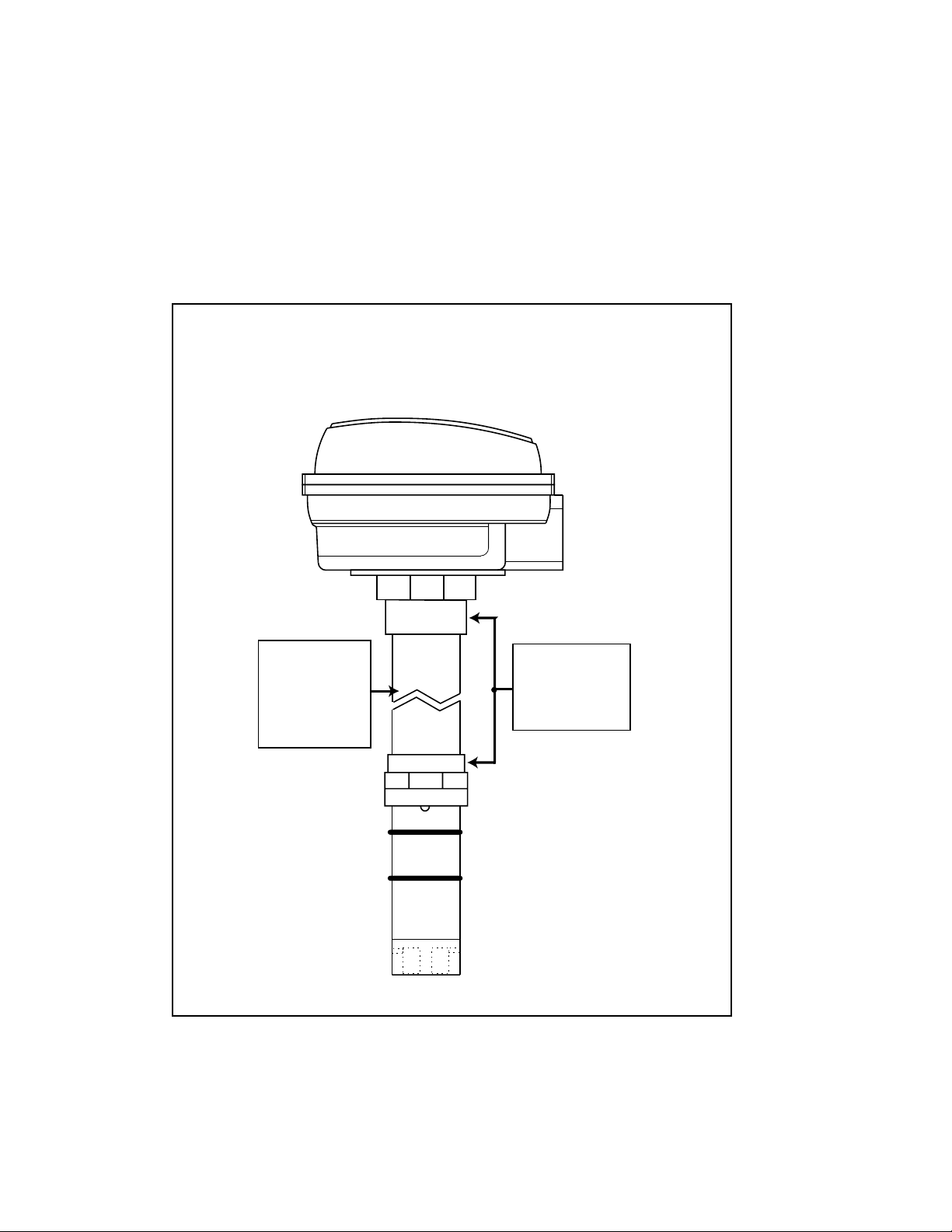
Figure 1
Transmitter submersion kit
and required extension
cable.
CDTX-80 Series Conductivity
Transmitter with Submersion Kit
Customer
supplied pipe
with 3/4 in.
NPT threads
Submersion
Kit/Assembly
Instructions
PHCN-86S
both ends
2
Page 5
2.1 Wet Calibration
Your CDTX-80 Series Conductivity Transmitter has
been electronically calibrated at the factory before
shipment. You will need to perform a wet
calibration to compensate for electrode variations.
Wet calibration compares the output of the
transmitter against the conductivity value of a test
solution.
Wet Calibration should be performed while the
CDTX-80 Series Conductivity Transmitter is being
permanently installed. When done carefully, you
can trim the transmitter accuracy to within ±1% of
full scale.
P4
Chapter 2
Calibration
P2
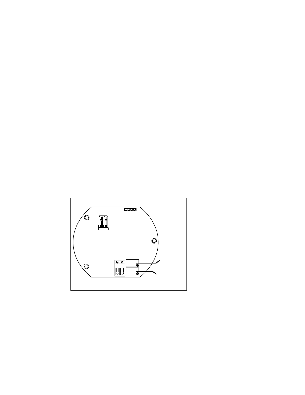
Figure 2
Adjustment pots
and connectors
R-R+
12
R26
R17
Zero Pot
(R26)
Gain/Span
Pot (R17)
3
Page 6
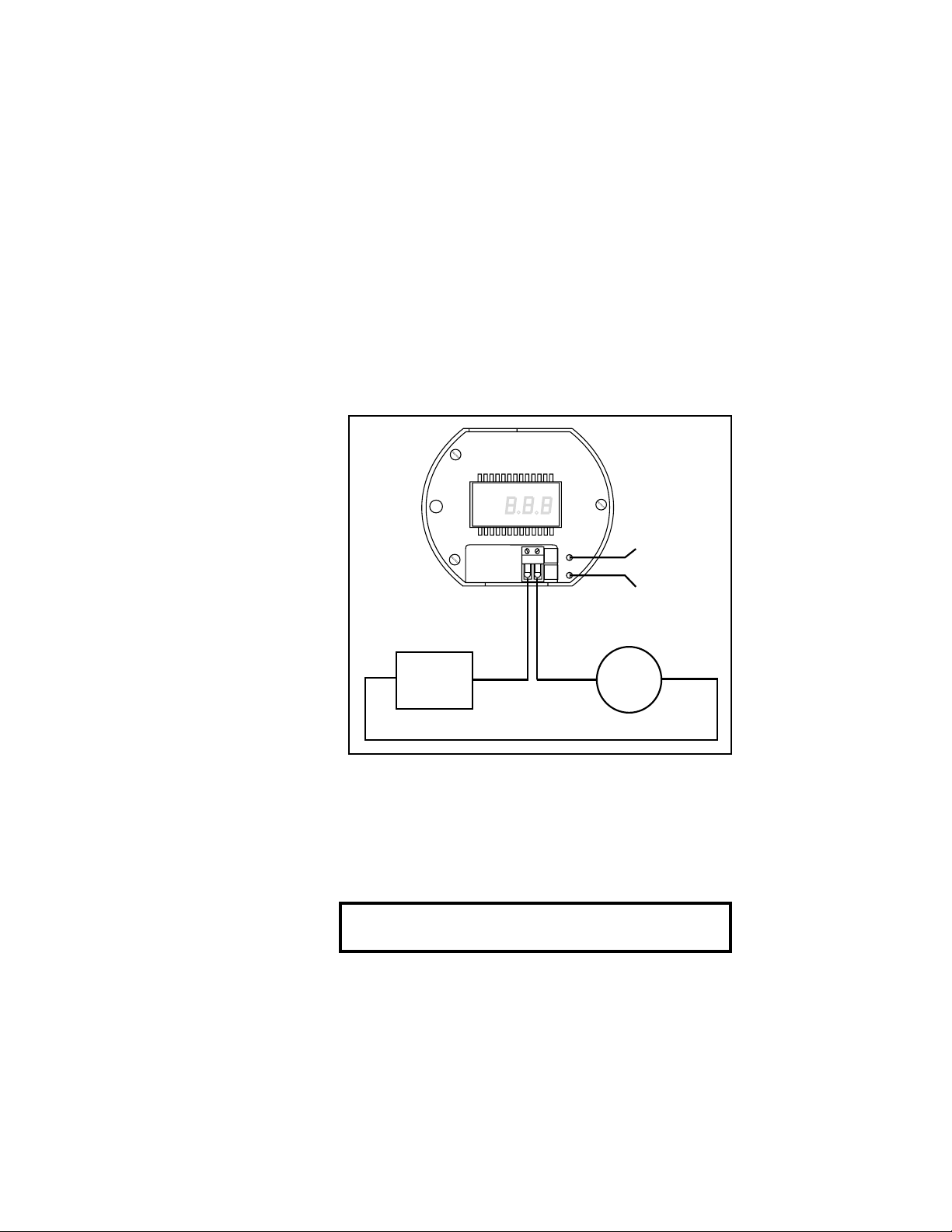
Figure 3
R+ R-
ZERO
SPAN
12
R26
R17
Zero Pot
(R26)
Span
Pot (R17)
+
+
-
-
10 to 30 VDC
Power
Supply
A
Ammeter
Transmitter Hook-up
NOTE:
The current output can be
monitored in several ways
(see Figure 8)
Equipment Required
• Small screwdriver
• Power supply (10 to 30 VDC)
• Ammeter
2.2 Calibration Procedure
1. Connect power supply to transmitter input
placing an ammeter in series with the input
power, see Figure 3.
2. With the Conductivity electrode in the air
(0 conductance) adjust the Zero pot (R26) for
4.00 mA.
3. Place the electrode into a solution of known
conductance and adjust the Span pot (R17) for
the corresponding mA value.
mA =
[(Known Cond./Full Scale Cond.) • 16 mA] + 4 mA
4. Remove the sensor from solution and verify that
the sensor reads 4.00 mA.
5. Repeat steps 2 through 4 as necessary.
4
Page 7
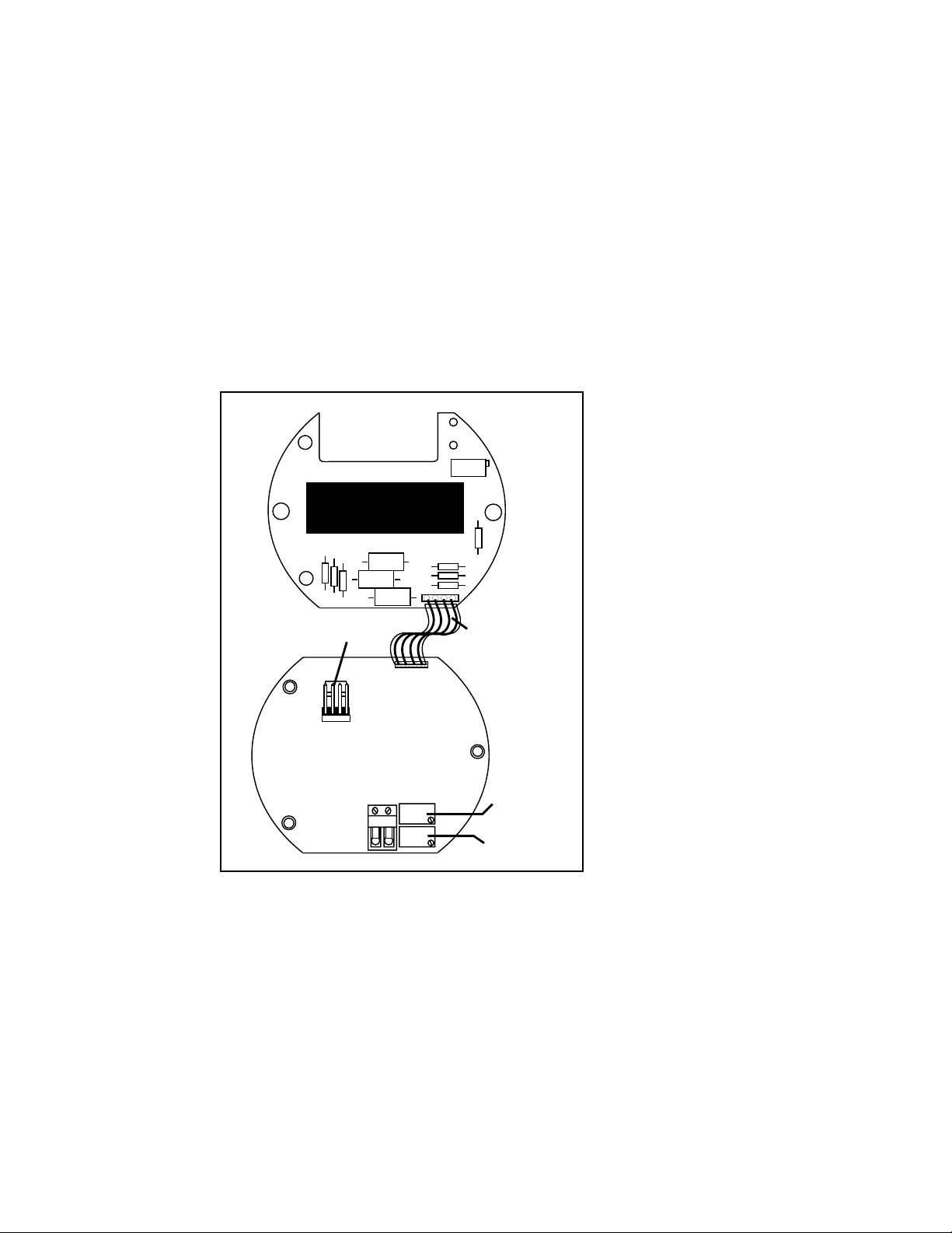
2.3 Installing Optional Display Board
The addition of the display board option
(CDTX-80-D) to the conductivity transmitter is
done in the following manner.
1. Remove snap-on cover allowing access to the
P4 connector.
2. Plug the four conductor ribbon cable into the
P4 connector, see Figure 4.
Display Board (Bottom View)
R2
RANGE
P3
Figure 4
Display Board
Installation Drawing
part no. CDTX-80-D
Sensor
connector
P2
P+
T+
SHLD
Pin 1 P+
12
1
R-R+
R26
R17
P4
Display/
Main bd.
Interface
Cable
Zero Pot
(R26)
Span
Pot (R17)
3. If necessary use a small blade (e.g Exacto knife)
to remove any conformal coating from the standoff
holes or calibration pot access holes.
4. Carefully snap the display board onto the
three standoffs.
5. Re-calibrate the instrument as explained in
section 2.2.
5
Page 8

ZERO
SPAN
Interface cable
connection to main
PC board. Located
on underside of LCD
board
Range Potentiometer;
Located on underside
of LCD board. Can be
adjusted through the
hole in the electronics
housing.
(Solution value ÷ Full Range) • 100 = Percentage
Figure 5
Range Potentiometer Location
2.4 Display Board Range Adjustment
The display board displays from zero to one
hundred percent of range. This PCB has a
one-point calibration which may need to be done
at installation.
1. Re-calibrate per section 2.2
2. Calculate percentage of full scale and adjust
Range pot on display board so that the display
shows the proper percent of Full Scale.
Model no. Full Range
CDTX-80 20 µS
CDTX-81 200 µS
CDTX-82 2,000 µS
CDTX-83 10,000 µS
T
he display board draws
approx. 200 µA of current.
When added, the transmitter
requires recalibration.
6
Page 9
3.1 General
This transmitter may be installed in harsh
environmental locations. However, when possible
the transmitter should be located so as to minimize
the effects of temperature gradients and to avoid
vibration and shock.
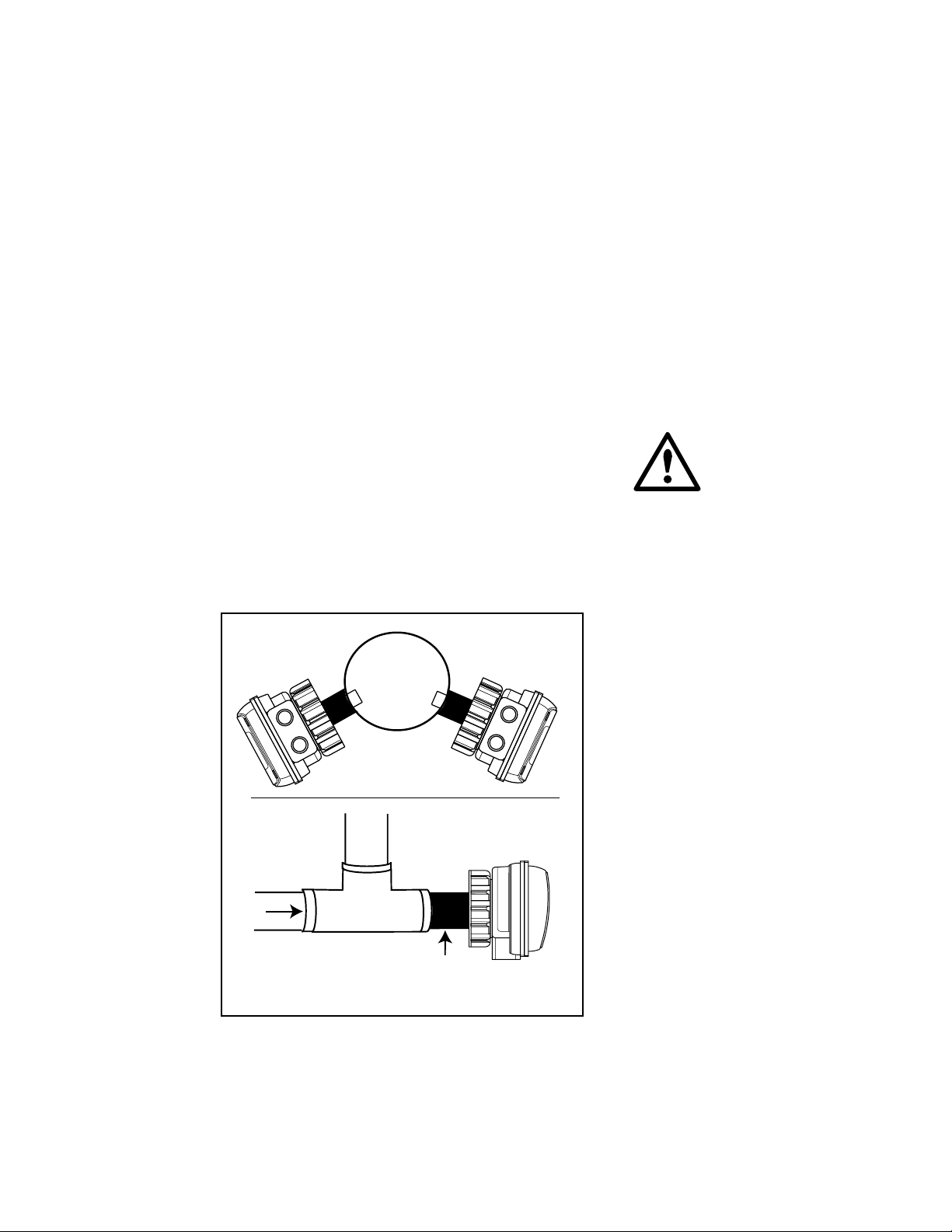
3.2 Positioning
In order to achieve good repeatable results care
must be taken in the placement of the sensor. It is
important that the sensor electrodes are fully
immersed in the process fluid. Flow rates around
the sensor must be limited so as not to produce air
pockets which will affect the signal path through
the fluid. We recommend that you do not mount
completely upside-down as sediments may become
trapped in the sensor and that you do not mount at
the very top of the pipe because the pipe might
not always be full.
8 O'clock 4 O'clock
Chapter 3
Installation
The information provided
on sensor positioning are
recommendations only. The
primary consideration is that
the electrodes are in full
contact with the process fluid.
If sediments are present we
recommend avoiding the 6
O'clock position.
OMEGA PHA-86
pipe adaptor
(1-1/4 in. NPT)
Figure 6
I
n-line Sensor
Positioning Diagram
7
Page 10

3.3 In-Line Installations
The CDTX-80 Series Conductivity Transmitter
sensor system is designed for installation into a
pipe using standard OMEGA Engineering fittings
(up to 4 inch), or the optional PHA-86 pipe
adaptor fitting. Refer to section 3.4 for additional
information.
Caution:
installing saddle
fittings, depressurize and drain pipe
before drilling fitting hole.
P
lastic "glue-on" Tee Fitting
Plastic "glue-on" Saddle
Fitting
When
3.4 In-line Fitting Options
These fittings provide the proper installation
parameters that are critical to the calibration of the
conductivity system.
Fitting Installation/Plastic Fittings
Tees:
• All tee fittings sold by OMEGA Engineering are
"glue-on" type except for the PVDF tees which
are thermally fused. Be aware that PVC and
CPVC tees require different types of primer and
cement.
• Tee fittings are available for pipes from 0.5 to
4 inches in diameter.
Saddles:
• Plastic "glue-on" saddles are available for lines
from 2 to 4 inches in diameter.
• 2 to 4 inch "glue-on" saddles require a 1-7/16
inch hole in the pipe. (O-ring not used with
glue-on type)
• The hole must be completely deburred to be
free of any projections.
• When assembling plastic saddles, the arrows
on the wedges must match the direction of the
arrows on the pipe saddle.
Misc:
OMEGA Engineering also offers a pipe adaptor
specifically designed for installing
8
Page 11

OMEGA Engineering analytical sensors into in-line
applications (PHA-86). This pipe adaptor can be
installed in any standard 1-1/4 inch FNPT pipe
fitting.
Fitting Installation/Metal Fittings
Welded fittings MUST be installed by a certified
welder.
The plastic sensor insert in the Weldolet fitting
MUST be removed during the welding process.
When reinstalled, it is important that the insert
be threaded to the proper height "H" dimension
to ensure full insertion of the sensor electrodes,
see page 10.
• 2 to 4 inch Weldolet fittings require a 1-7/16
inch hole in the pipe.
• The hole must be completely deburred to be
free of any projections before installing the
Weldolet fitting.
Pipe Tees: Metal Pipe Tees are available for 0.5
to 2 inch metal pipes. Materials include iron,
carbon steel, stainless steel, and copper or
bronze. All tees are threaded with NPT threads
except for copper and bronze tees, which have
solder or braze type fittings.
"Weld-on" Weldolet Fitting
Metal Pipe Tee Fitting
• Use thread sealant compound on fittings with
threaded connections.
9
Page 12

"H"
Weldolet "H" dimension
part number inches
FP-5325CS 2.33
FP-5330CS 2.32
FP-5340CS 2.30
FP-5325 2.33
FP-5330 2.32
FP-5340 2.30
Weldolet Fitting
10
3.5 Submersible Installations
CDTX-80 Series Conductivity Transmitter sensor
system can be made submersible through the use
of the submersible kit PHCN-86S and extension
cable cable length from -01 to -12 ft. (see
Figure 1 page 2).
Page 13
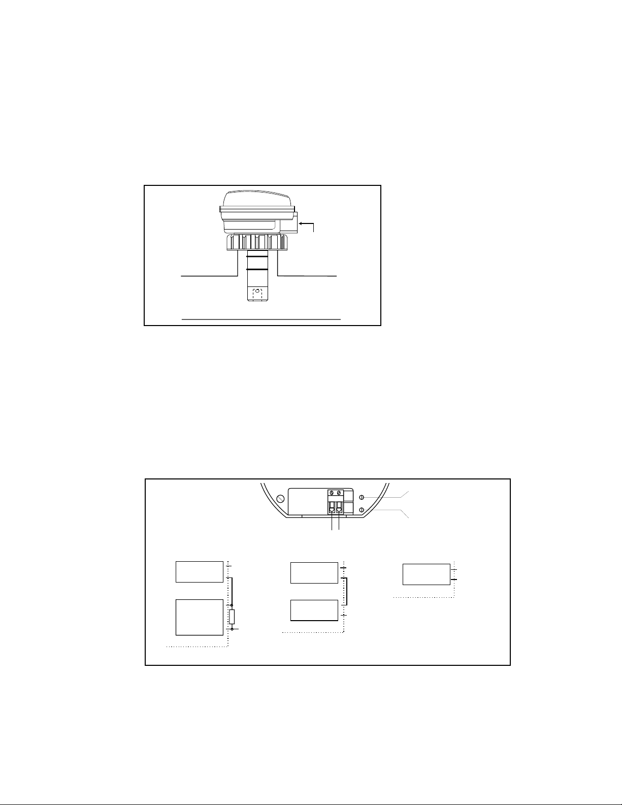
3.6 Electrical Installation
The transmitter has a 1/2 inch conduit opening
for power/signal wiring, see Figure 7.
1/2 in. NPT for
conduit (2 places)
DIN Version:
PG 13.5 metric
thread
The sensor input connection is located on the
lower PCB (below optional Display PCB). To
access the connector, remove the housing cover
followed by the electronics cover (snap on/off).
The connector is now accessible between the
Display PCB (if installed) and the Main PCB.
Signal wiring to the R+ and R- terminals need not
be shielded, but 2-conductor shielded twisted-pair
cable should be used for best results (Min. #22
AWG).
Figure 7
CDTX-80 Series Conductivity
Transmitter In-line Installation
Figure 8
Transmitter Connection
Diagram
Connection to device
with separate power supply
10 to 30
VDC
Measuring
device with
1 to 5 VDC
input
Voltage = Resistance • Current
+
+
-
-
R+
Resistor
250 Ω*
R-
*Note
ZERO
R26
12
SPAN
R17
R+ R-
Connection to device
with separate power supply
+
10 to 30
VDC
Measuring
device
R+
-
R-
+
Zero Pot
(R26)
Span
Pot (R17)
Connection to device
with internal power supply
+
Measuring
device
R+
-
R-
11
Page 14

Signal wiring should not run in conduit
or in open trays with HVAC wiring and should not
be run near heavy electrical equipment. Leads
should be color coded for polarity identification.
The conduit connection on the transmitter housing
should be sealed or plugged to avoid accumulation of moisture in the housing. If the conduit is not
sealed, the transmitter should be mounted with the
opening downward for draining.
Signal wiring may be ungrounded or grounded at
any place in the signal loop. Power supply regulation is not critical. Make sure that the power supply
source conforms to the requirements of the
transmitter and that the current rating of the supply
is not exceeded, particularly if more than one
transmitter is connected to the supply in parallel.
NOTE:
This transmitter is designed to eliminate ground
loops and other electrical interactions between
system components even if several transmitters are
powered by a common supply in parallel.
12
Make sure that electrical characteristics of the
remote output device are compatible with the
transmitter output: Total load resistance must not
exceed 700 ohms using a 24 VDC power
supply. Total load resistance is the sum of the
individual resistances of all devices which are
connected in series with the signal output lead.
Equation:
RL = VS-10/0.02
where
RL = Load Resistance in ohms
VS = Supply Voltage
10 = Minimum operating voltage
0.02 = 20 mA (maximum current)
Page 15

4.1 Maintenance Tips
The electrodes contact the solution and transfer a
signal through the solution being measured. It is
recommended that the electrodes maintain contact
with fluid. If allowed to air dry, precipitates may
form on the electrodes causing higher than normal
readings and possibly contaminating the process
fluid. If precipitates form, the electrodes may be
cleaned by immersing the sensor in warm water
and scrubbing the electrodes with a soft nylon
brush.
It is important that the sensor is not exposed to oils
which may coat the electrodes. This may seriously
affect the readings.
In extreme cases it may be necessary to clean
the sensor with alcohol to remove oils. We
recommend using a cotton swab and brushing the
electrode clean instead of dipping the entire
sensor body in acetone.
Chapter 4
Conductivity
Sensor
Maintenance
In submersible applications the sensor should be
located fully immersed and away from the
presence of any bubbles.
In some instances it may be necessary to devise
a periodic maintenance schedule to clean the
electrodes and verify calibration.
13
Page 16

4.2 Troubleshooting Guide
Problem ActionCause
•Application range exceeds the
electronics range.
Display/output
reads off scale
•Unit is not properly calibrated
• Check unit model number,
see Unpacking and Inspection
section (opposite page #1)
• Re-calibrate, see page 4
Display/output
reads zero
(4 mA)
Display is blank/
no current
Transmitter cannot
be calibrated
(insufficient Zero
adjust)
Transmitter cannot
be calibrated
(insufficient Gain
adjust)
•Range pot misadjusted
•Application range below
the electronics range
• Sensor not connected
• System power or ground OPEN
• Gain pot set too high
• Incorrect operating range
• Excessive Quiescent
current
• Incorrect operating range
• Unit not calibrated
• Output transistor damaged
• Re-calibrate display,
see page 5
•Check unit model number,
see Unpacking and Inspection
section (opposite page #1)
•Check sensor connection
• Check system wiring
• Reduce Gain/Span pot
adjust
• Check unit model number,
see Unpacking and
Inspection section (opposite
page #1)
• Send for repair
• Check unit model number,
see Unpacking and
Inspection section (opposite
page #1)
• Re-calibrate, see page 4
• Send for repair
Transmitter output
changes erratically
14
• Air bubbles contacting sensor
• Coated electrodes
• Leaking submersion kit
• Check installation
• Clean sensor, see page 11
• Clean/replace cable
install new seal
Page 17

Optional Display: 0 - 100%, 2-1/2 digit LCD
(factory installation recommended),
CDTX-80-D
Loop power: 10 to 30 VDC
Loop impedance:
• 1Ω @ 10 VDC
• 100Ω @ 12 VDC
• 1000Ω @ 30 VDC
Electronics operating temp:
• -15 to 50 °C (5 to 122 °F)
Max sensor pressure/temperature:
• 7 bar @ 20 °C (100 psi @ 68 °F)
• 1.7 bar @ 90 °C (25 psi @ 194 °F)
Operating ranges:
• CDTX-80 0 to 20 µS 0.05 cell
• CDTX-81 0 to 200 µS 0.05 cell
• CDTX-82 0 to 2,000 µS 2.0 cell
• CDTX-83 0 to 10,000 µS 2.0 cell
Current output: 2-wire, 4 to 20 mA signal
Accuracy: ±1% of range
Specifications
Relative Humidity: 0 to 95%, non-condensing
Enclosure materials:
• Electronics enclosure: Glass-filled PP, NEMA 4X/IP65
• Enclosure seal: Viton®
• Window: Polycarbonate
Wetted sensor materials:
• Sensor body: Glass-filled PP
• Electrodes: Titanium
• Sensor o-rings (2): Viton®
• Optional o-rings: EPR, FPP-1224-0021
Kalrez, FPP-1228-0021
Immunity: EN50082-1
Emissions: EN55011
Agency Approvals: CE
15
Page 18

Figure 9
4.2 in./
107 mm
3.5 in./
89 mm
1/2 in. NPT
For Conduit
(2 places)
DIN Version:
PG 13.5
metric thread
4.2 in./
107 mm
3.5 in./
89 mm
1/2 in. NPT
For Conduit
(2 places)
DIN Version:
PG 13.5
metric thread
CDTX-80 Series Conductivity
Transmitter Dimensional Views
0.05 Cell Constant
-1 (0 to 20 µS)
-2 (0 to 200 µS)
2.0 Cell Constant
-3 (0 to 2,000 µS)
-4 (0 to 10,000 µS)
16
Page 19

NOTES:
17
Page 20

NOTES:
18
 Loading...