

Page 1
CDTX
-
45T
Portable Toroidal Conductivity
Page 2
Page 3

Table of Contents
TABLE OF FIGURES................................................................................................................................................ 4
PART 1 - INTRODUCTION ..................................................................................................................................... 5
1.1 General .......................................................................................................................................................... 5
1.2 Features ......................................................................................................................................................... 5
1.3 CDTX-45T System Specifications ................................................................................................................ 7
1.4 CDTX-45T Performance Specifications ....................................................................................................... 8
PART 2 –SYSTEM SPECIFICATIONS .................................................................................................................. 9
2.1 General .......................................................................................................................................................... 9
2.2 Portable Handle ............................................................................................................................................. 9
PART 3 – ELECTRICAL INSTALLATION ..........................................................................................................11
3.1 General .........................................................................................................................................................11
3.2 Direct Sensor Connection ............................................................................................................................11
3.3 Sensor Connection .......................................................................................................................................12
PART 4 – CONFIGURATION .................................................................................................................................13
4.1 General .........................................................................................................................................................13
4.2 Hardware Details .........................................................................................................................................13
4.3 User Interface ...............................................................................................................................................14
4.4 Keys .........................................................................................................................................................15
4.5 Display .....................................................................................................................................................15
4.6 Software .......................................................................................................................................................17
4.61 Software Navigation ...............................................................................................................................17
4.62 Measure Menu [MEASURE] ...................................................................................................................19
4.63 Calibration Menu [CAL].............................................................................................................................20
4.64 Configuration Menu [CONFIG] .............................................................................................................21
4.65 Diagnostics Menu [DIAG] .........................................................................................................................23
PART 5 – CALIBRATION .......................................................................................................................................26
5.1 Overview and Methods ................................................................................................................................26
5.11 1-Point Calibration Explained ..................................................................................................................26
5.12 Zero Cal Calibration Explained ...............................................................................................................27
5.2 Performing a 1-Point Calibration .................................................................................................................27
5.3 Performing a Cell Factor Calibration ...........................................................................................................29
5.4 Performing a Sensor Zero Calibration .........................................................................................................30
5.5 Temperature Calibration ..............................................................................................................................30
5.6 TC Factor Calibration ..................................................................................................................................31
PART 6 – SYSTEM MAINTENANCE ....................................................................................................................33
6.1 System Checks .............................................................................................................................................33
6.2 Instrument Checks .......................................................................................................................................33
6.3 Display Messages ........................................................................................................................................34
O&M Manual
3
Page 4

Table of Figures
FIGURE 1 – PORTABLE UNIT OVERVIEW ......................................................................................... 9
FIGURE 2 – CDTX-45T BATTERY POWERED DIMENSIONS ............................................................. 10
FIGURE 3 - SENSOR CABLE PREPARATION ................................................................................... 11
FIGURE 4 - LOOP POWERED CONNECTION, CDTX-45T TRANSMITTER ........................................... 12
FIGURE 5 - USER INTERFACE ....................................................................................................... 14
FIGURE 6 - SOFTWARE MAP ........................................................................................................ 18
FIGURE 7 - NACL REFERENCE SOLUTION FOR CALIBRATION ......................................................... 27
O&M Manual
4
Page 5

CDTX-45T Portable Toroidal Conductivity System Part 1 - Introduction
Part 1 - Introduction
1.1 General
The Model CDTX-45T Portable Conductivity monitor/analyzer provides an
extremely versatile measurement system for monitoring and control of
conductivity over the range of 20 µS/cm to 2.000 Siemen/cm.
A battery card converts the instrument into a robust, portable measurement
system that operates on one 9 VDC battery. Since this system utilizes the same
high performance toroidal sensor as the standard configurations, it is a very
durable portable monitoring system. It can be used on its own, or it can be used
with other permanently installed continuous monitoring systems to simplify
calibration by using the calibrate-by-reference method.
The CDTX-45T portable displays conductivity and sensor temperature. The
instrument is used with the high performance toroidal sensors.
1.2 Features
· Standard CDTX-45T electronic transmitters are designed to be a fully isolated,
battery operated instrument. The monitor can be quickly converted to either a
loop power transmitter or line powered analyzer.
· Output Hold, Output Simulate, Output Alarm, and Output Delay Functions. All
forced changes in output condition include bumpless transfer to provide gradual
return to on-line signal levels and to avoid system control shocks on both analog
outputs.
· Two 10-bit, isolated, 0-2.5 VDC analog outputs may be configured to track
conductivity and temperature. Both analog outputs can be individually
programmed to fail to specific values.
· Large, high contrast, custom Super-Twist display provides excellent readability
even in low light conditions. The secondary line of display utilizes 5x7 dot matrix
characters for clear message display. Two of four measured parameters may be
on the display simultaneously.
· Sensor diagnostics monitor electrode coating/fouling, sensor leaks, and RTD
condition. Diagnostic messages provide a clear description of any problem with
no confusing error codes to look up. Messages are also included for diagnosing
calibration problems.
O&M Manual
5
Page 6

CDTX-45T Portable Toroidal Conductivity System Part 1 - Introduction
· Quick and easy one-point calibration method and sensor zero-cal. To provide
high accuracy, all calibration methods include stability monitors that check
temperature and main parameter stability before accepting data.
· High accuracy Pt1000 temperature input. Temperature element can be user
calibrated.
· Security lock feature to prevent unauthorized tampering with transmitter settings.
All settings can be viewed while locked, but they cannot be changed.
· High reliability, microprocessor-based system with non-volatile memory back-up
that utilizes no batteries. Low mass, surface mount PCB construction containing
no adjustment potentiometers. All factory calibrations stored in non-volatile
EEPROM.
O&M Manual
6
Page 7

CDTX-45T Portable Toroidal Conductivity System Part 1 - Introduction
1.3 CDTX-45T System Specifications
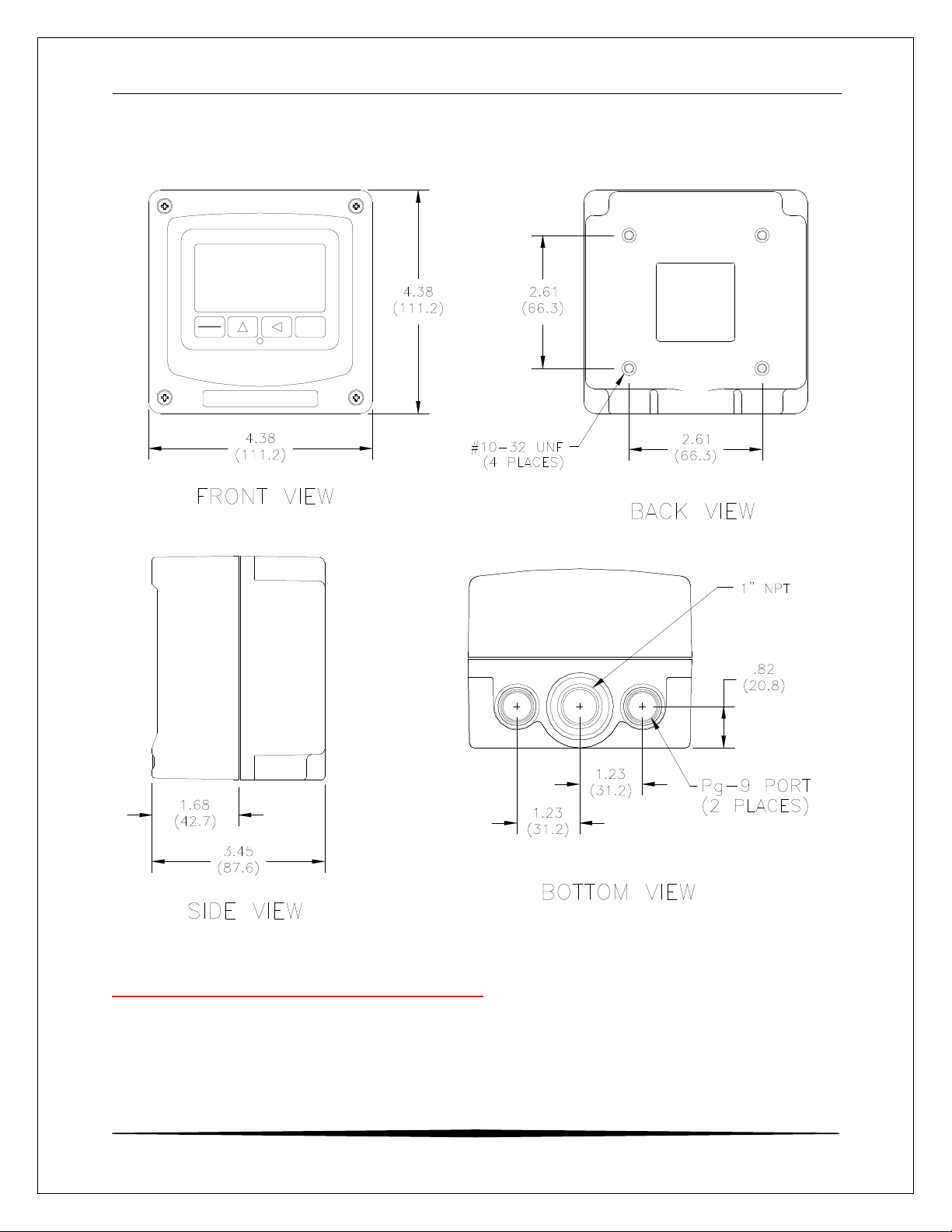
Enclosure NEMA 4X, polycarbonate, stainless steel hardware,
weatherproof and corrosion resistant,
HWD: 4.4" (112 mm) × 4.4" (112 mm) × 3.5" (89 mm)
Mounting Options Hand held, wall, panel, pipe/header.
Weight DC transmitter configuration: 1 lb. (0.45 kg)
Display Large, high-contrast, Super-Twist (STN) LCD;
4-digit main display with sign, 0.75" (19.1 mm) seven-
segment characters;
12-digit secondary display, 0.3" (7.6 mm) 5×7 dot matrix
Keypad 4-key membrane type with tactile feedback, polycarbonate
Ambient Temperature Service, -20 to 60 °C (-4 to 140 ºF)
Storage, -30 to 70 °C (-22 to 158 ºF)
Ambient Humidity 0 to 95%, indoor/outdoor use, non-condensing to rated
Electrical Certification Ordinary Location, cCSAus (CSA and UL standards - both
EMI/RFI Influence Designed to EN 61326-1
Output Isolation 600 V galvanic isolation
Filter Adjustable 0-9.9 minutes additional damping to 90% step
Temperature Input Pt1000 RTD with automatic compensation
Displayed Parameters Main input, 0.0 μS to 2000 mS
% Concentration (if enabled)
Sensor temperature, -10.0 to 110.0 °C (14 to 230ºF)
Main Parameter Ranges Automatic or manual selection of the following:
0 to 2000 mS
0.0 to 2.000 mS
0.00 to 20.00 mS
0.0 to 200.0 mS
0 to 2000 mS
0.000 to 2.000 S
characters
with UV coating, integral EMI/static shield and conductively
coated window
ambient temperature range
approved by CSA), pollution degree 2, installation category
2
input
O&M Manual
7
Page 8

CDTX-45T Portable Toroidal Conductivity System Part 1 - Introduction
Battery Operated:
Power: Generic 9 VDC alkaline battery, low battery indication at
6.75 VDC. Lithium 9 VDC battery recommended for max
performance.
Enclosure: NEMA 4X, polycarbonate, stainless steel hardware,
weatherproof and corrosion resistant,
HWD: 4.4" (112 mm) x 4.4" (112 mm) x 3.5" (89 mm)
Mounting Options Supplied with carrying handle and cable glands installed.
Outputs: Two 0-2.5 VDC isolated outputs are provided on for
connection to data recorders, etc.
Battery Life: Approximately 100 hours with alkaline battery. Use of
lithium cell increases life to approximately 300 hours.
1.4 CDTX-45T Performance Specifications
(Common to all variations)
Accuracy 0.3% of span or better (± 0.1 μS)
Repeatability 0.3% of span or better (± 0.1 μS)
Sensitivity 0.05% of span (± 0.1 μS)
Stability 0.1% of span per 24 hours, non-cumulative
Warm-up Time 7 seconds to rated performance
Supply Voltage Effects ± 0.05% span
Instrument Response Time 12 seconds to 90% of step input at lowest setting
Temperature Drift Span or zero, 0.03% of span/°C
Max. Sensor-Instrument 200 ft. (18.3 meters)
Distance
Sensor Type Toroidal - 6 wire (paired and shielded) input
O&M Manual
8
Page 9
CDTX-45T Portable Toroidal Conductivity System Part 2 – System Specifications
Part 2 –System Specifications
2.1 General
The CDTX-45T Portable Conductivity System comes complete with a specially
designed handle that allows the system to be comfortably carried, or quickly
strapped to a railing. Although the system is designed to be a portable system, it
can be permanently mounted for longer term field use. This is possible due to
the very long battery life spans that can be achieved with the system.
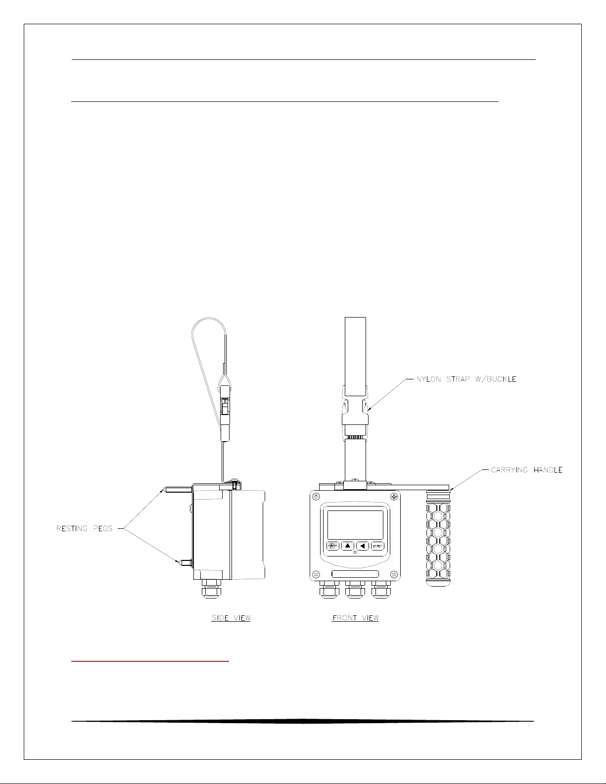
2.2 Portable Handle
A removable handle is included with each unit that provides not only comfortable
transportation of the system, but the integral locking strap allows the system to
be quickly mounted to pipes or rails for longer term use in one area.
Figure 1 – Portable Unit Overview
O&M Manual
9
Page 10
CDTX-45T Portable Toroidal Conductivity System Part 2 – System Specifications
MENU
ESC
ENTER
Figure 2 – CDTX-45T Battery Powered Dimensions
O&M Manual
10
Page 11
CDTX-45T Portable Toroidal Conductivity System Part 3 – Electrical Installation
Part 3 – Electrical Installation
3.1 General
The sensor cable can be quickly connected to the terminal strip by
matching the wire colors on the cable to the color designations on
the label in the monitor. Keep signal cable away from AC power
lines, adjustable frequency drives, motors, or other noisy electrical
signal lines.
3.2 Direct Sensor Connection
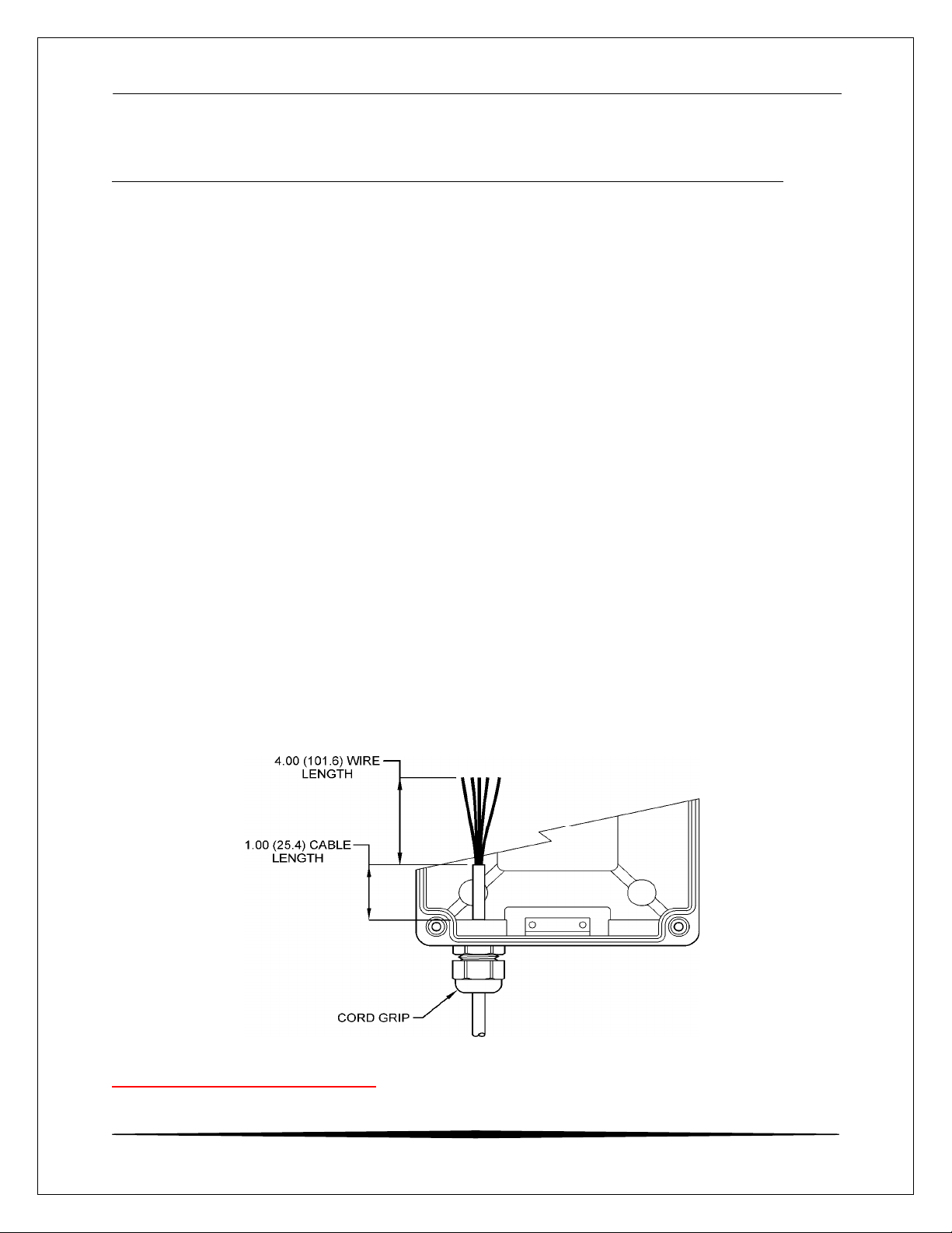
Sensor connections are made in accordance with Figure 3. The
sensor cable can be routed into the enclosure through one of cordgrips supplied with the unit. Some loose cable is needed near the
installation point so that the sensor can be inserted and removed
easily from the flowcell.
Cord-grips used for sealing the cable should be snugly tightened
after electrical connections have been made to prevent moisture
incursion. When stripping cables, leave adequate length for
connections in the transmitter enclosure as shown below. The
standard 20 ft. sensor cable normally supplied with the system is
already stripped and ready for wiring. This cable can be cut to a
shorter length if desired to remove extra cable in a given
installation. Do not cut the cable so short as to make installation
and removal of the sensor difficult.
.
Figure 3 - Sensor Cable Preparation
O&M Manual
11
Page 12
CDTX-45T Portable Toroidal Conductivity System Part 3 – Electrical Installation
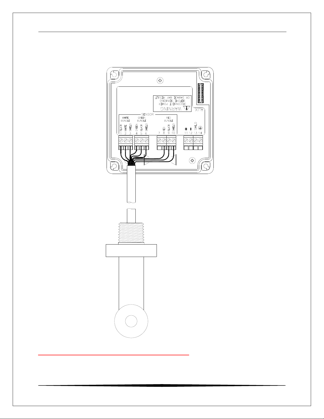
3.3 Sensor Connection
Figure 4 - Loop Powered Connection, CDTX-45T Transmitter
Notes: 1. Voltage between Terminals 11 and 12 MUST be between 16 and 35 VDC.
O&M Manual
12
Page 13

CDTX-45T Portable Toroidal Conductivity System Part 4 – Configuration
Part 4 – Configuration
4.1 General
To turn the system ON, simply press and hold the MENU key for approximately 5
seconds and the display will come on. The instrument will turn off automatically
after 30 minutes if no keys are pressed – optimizing battery life. This mode of
operation is ideal for portable operation where intermediate readings are being
taken. Assuming the instrument is used perhaps an hour per day, this would
result in a battery lifespan of about 3 months. For continuous operation with no
automatic shut-off, turn the Auto-OFF feature to OFF in the DIAG menu. With a
standard 9 VDC alkaline battery, this would produce about 250 hours of
operation. Installing a 9 VDC lithium battery instead of alkaline will increase
operation time in all modes by 4 times. It should be noted that rechargeable 9
VDC batteries reduce operational times dramatically, as they typically contain
much less energy than standard batteries.
The PWR switch disconnects the 9 VDC battery and is only used to disconnect
the battery if the system is not to be used for a long period of time (> 3 months of
storage). Otherwise, leave this switch in the ON position. The red dip switch is
only for factory use.
The "B" will flash on the display next to the main measurement indication when
the instrument requires battery replacement. If the battery is not replaced,
eventually the unit may not turn on in the normal operating mode. Once the low
battery condition is indicated, the instrument will only stay powered for 10
minutes.
4.2 Hardware Details
The CDTX-45T portable instrument is operated by software settings.
Note: Do not attempt to connect external DC or AC power supplies
to the portable unit or severe damage will result.
Note: The power terminals MUST NOT be connected to an external
power supply when this board is installed or serious damage
will result.
O&M Manual
13
Page 14

CDTX-45T Portable Toroidal Conductivity System Part 4 – Configuration
ENTER
MENU ICONS
12-CHARACTER
4.3 User Interface
The user interface for the instrument consists of a custom display and a
membrane keypad. All functions are accessed from this user interface (no
internal jumpers, pots, etc.).
SIGN
RELAY/LO-BAT
INDICATOR
4-KEY USER
INTERFACE
RELAY
INDICATOR
A
B
MENU
ESC
4-DIGIT
MAIN DISPLAY
MENU ICONS
CAL
UNITS
CONF
12-CHARACTER
SECONDARY
DISPLAY
MEMBRANE
KEYPAD
DIAG
FAIL
HOLD
UNITS
SECONDARY
DISPLAY
MEMBRANE
KEYPAD
MENU/ESCAPE
KEY
UP ARROW
Figure 5 - User Interface
O&M Manual
KEY
ENTER KEY
LEFT ARROW
KEY
14
Page 15

CDTX-45T Portable Toroidal Conductivity System Part 4 – Configuration
4.4 Keys
All user configurations occur through the use of four membrane keys. These
keys are used as follows:
MENU/ESC To scroll through the menu section headers or to escape
from anywhere in software. The escape sequence allows
the user to back out of any changes in a logical manner.
Using the escape key aborts all changes to the current
screen and backs the user out one level in the software tree.
The manual will refer to this key as either MENU or ESC,
depending upon its particular function. In the batterypowered version, this is also the ON button.
UP (arrow) To scroll through individual list or display items and to
change number values.
LEFT (arrow) To move the cursor from right to left during changes to a
number value.
ENTER To select a menu section or list item for change and to store
any change.
4.5 Display
The large custom display provides clear information for general measurement
use and user configuration. There are three main areas of the display: the main
parameter display, the secondary message line, and the icon area.
Main Parameter During normal operation, the main parameter display
indicates the present process input with sign and units. This
main display may be configured to display any of the main
measurements that the system provides. During
configuration, this area displays other useful set-up
information to the user.
O&M Manual
15
Page 16

CDTX-45T Portable Toroidal Conductivity System Part 4 – Configuration
Lower Line During normal operation, the lower line of the display
indicates user-selected secondary measurements that the
system is making. This also includes calibration data from
the last calibration sequence and the transmitter model
number and software version. During configuration, the
lower line displays menu items and set-up prompts to the
user. Finally, the lower line will display error messages
when necessary. For a description of all display messages,
refer to Section 7.3.
Icon Area The icon area contains display icons that assist the user in
set-up and indicate important states of system functions.
The CAL, CONFIG, and DIAG icons are used to tell the user
what branch of the software tree the user is in while scrolling
through the menu items. This improves software map
navigation dramatically. Upon entry into a menu, the title is
displayed (such as CAL), and then the title disappears to
make way for the actual menu item. However, the icon stays
on.
HOLD The HOLD icon indicates that the analog output of the
transmitter has been put into output hold. In this case, the
output is locked to the last input value measured when the
HOLD function was entered. HOLD values are retained
even if the unit power is cycled.
FAIL The FAIL icon indicates that the system diagnostic function
has detected a problem that requires immediate attention.
This icon is automatically cleared once the problem has
been resolved.
O&M Manual
16
Page 17

CDTX-45T Portable Toroidal Conductivity System Part 4 – Configuration
4.6 Software
The software of the CDTX-45T is organized in an easy to follow menu-based
system. All user settings are organized under five menu sections: Measure,
Calibration [CAL], Configuration [CONFIG], Control [CONTROL] and Diagnostics
[DIAG].
Note: The default Measure Menu is display-only and has no menu icon.
4.61 Software Navigation
Within the CAL, CONFIG, CONTROL, and DIAG menu sections is a list of selectable items. Once a
selectable items. Once a menu section (such as CONFIG) has been selected with the MENU key,
with the MENU key, the user can access the item list in this section by pressing either the ENTER
either the ENTER key or the UP arrow key. The list items can then be scrolled through using the
through using the UP arrow key. Once the last item is reached, the list wraps around and the first
around and the first list item is shown again. The items in the menu sections are organized such
organized such that more frequently used functions are first, while more permanent function
permanent function settings are later in the list. See Figure 6 - Software Map
for a visual description of the software.
Each list item allows a change to a stored system variable. List items are
designed in one of two forms: simple single variable, or multiple variable
sequence. In the single variable format, the user can quickly modify one
parameter - for example, changing temperature display units from °F to °C. In
the multiple variable sequence, variables are changed as the result of some
process. For example, the calibration of conductivity generally requires more
than one piece of information to be entered. The majority of the menu items in
the software consist of the single variable format type.
Any data that may be changed will be flashing. This flashing indicates user entry
mode and is initiated by pressing the ENTER key. The UP arrow key will
increase a flashing digit from 0 to 9. The LEFT arrow key moves the flashing
digit from right to left. Once the change has been completed, pressing ENTER
again stores the variable and stops the flashing. Pressing ESC aborts the
change and also exits user entry mode.
The starting (default) screen is always the Measure Menu. The UP arrow key is
used to select the desired display. From anywhere in this section the user can
press the MENU key to select one of the four Menu Sections.
The UP arrow icon next to all list items on the display is a reminder to scroll
through the list using the UP arrow key.
To select a list item for modification, first select the proper menu with the MENU
key. Scroll to the list item with the UP arrow key and then press the ENTER key.
O&M Manual
17
Page 18

CDTX-45T Portable Toroidal Conductivity System Part 4 – Configuration
This tells the system that the user wishes to perform a change on that item. For
single item type screens, once the user presses the ENTER key, part or all of the
variable will begin to flash, indicating that the user may modify that variable using
the arrow keys. However, if the instrument is locked, the transmitter will display
the message Locked! and will not enter user entry mode. The instrument must
be unlocked by entering the proper code value to allow authorized changes to
user entered values. Once the variable has been reset, pressing the ENTER key
again causes the change to be stored and the flashing to stop. The message
Accepted! will be displayed if the change is within pre-defined variable limits. If
the user decides not to modify the value after it has already been partially
changed, pressing the ESC key aborts the modification and returns the entry to
its original stored value.
In a menu item which is a multiple variable sequence type, once the ENTER key
is pressed there may be several prompts and sequences that are run to complete
the modification. The ESC key can always be used to abort the sequence
without changing any stored variables.
MENU
SECTIONS
LIST
ITEMS
Start
MEASURE
(display only)
Temperature
Loop Current #1
Loop Current #2
Slope
TDS
Model /Software Ver
Figure 6 - Software Map
CAL
or
Cal Cond.
Cal Temp
Set Range
Cal Zeros
CONFIG
or
Entry Lock
Set Delay
Contrast
Main Display
Solu Comp
Ref Temp
TDS Factor
Out1 Mode
Out2 Mode
Temp Units
CONTROL
or
Set 0mV (#1)
Set 2.5V (#1)
Set 0mV (#2)
Set 2.5V (#2)
DIAG
or
Set Hold
Fault List
Sim Out
Auto-Off
Backlight
Set Default
O&M Manual
18
Page 19

CDTX-45T Portable Toroidal Conductivity System Part 4 – Configuration
4.62 Measure Menu [MEASURE]
The default menu for the system is the display-only menu MEASURE. This menu
is a display-only measurement menu, and has no changeable list items. When
left alone, the instrument will automatically return to this menu after
approximately 30 minutes. While in the default menu, the UP arrow allows the
user to scroll through the secondary variables on the lower line of the display. A
brief description of the fields in the basic transmitter version is as follows:
TRANSMITTER MEAS SCREENS:
25.7C Temperature display. Can be displayed in C or F,
depending on user selection. A small “m” on the left side of
the screen indicates the transmitter has automatically
jumped to a manual 25C setting due to a failure with the
temperature signal input.
20.00 mA Transmitter output current (when set-up for loop power)
Slope = 100% Sensor calibration slope (updated after successful calibration
has been completed)
TDS = 200 mgL Total Dissolved Solids (TDS). Displays TDS of the process.
v1.00 Transmitter software version number.
Note: A display test (all segments ON) can be actuated by pressing and
holding the ENTER key while viewing the model/version number on
the lower line of the display.
The MEASURE screens are intended to be used as a very quick means of
looking up critical values during operation or troubleshooting.
O&M Manual
19
Page 20

CDTX-45T Portable Toroidal Conductivity System Part 4 – Configuration
4.63 Calibration Menu [CAL]
The calibration menu contains items for frequent calibration of user parameters.
There are three items in this list: Cal Cond, Cal Temp, and Cal TC Factor.
Cal Cond The conductivity calibration function allows the user to adjust
the transmitter offset and span reading to match reference
buffers, or to adjust the sensor offset to match the sample
reading. See Part 5 - Calibration for more details.
Cal Temp The temperature calibration function allows the user to
adjust the offset of the temperature response by a small
factor of ±5 °C. The temperature input is factory calibrated
to very high accuracy. However, long cable lengths and
junction boxes may degrade the accuracy of the temperature
measurement in some extreme situations. Therefore, this
feature is provided as an adjustment. See Part 5 Calibration for more details.
Set Range This function allows the user to set the display range of the
transmitter for a specific application. Once set, all output
functions use this display range to establish configuration
settings. Press ENTER to initiate user entry mode, and the
value will flash. Use the arrow key to modify the range for
the desired range and then press ENTER.
Cal Zeros This function calibrates all range zero-points to the specific
sensor being used. This function is only required to be
performed once at initial start-up or when the sensor has
been replaced. See Part 5 - Calibration for more details.
O&M Manual
20
Page 21

CDTX-45T Portable Toroidal Conductivity System Part 4 – Configuration
4.64 Configuration Menu [CONFIG]
The Configuration Menu contains all of the general user settings:
Entry Lock This function allows the user to lock out unauthorized
tampering with instrument settings. All settings may be
viewed while the instrument is locked, but they cannot be
modified. The Entry Lock feature is a toggle-type setting;
that is, entering the correct code will lock the transmitter and
entering the correct code again will unlock it. The code is
preset at a fixed value. Press ENTER to initiate user entry
mode and the first digit will flash. Use arrow keys to modify
value. See the end of this manual for lock/unlock code.
Press ENTER to toggle lock setting once code is correct.
Incorrect codes do not change state of lock condition.
Set Delay The delay function sets the amount of damping on the
instrument. This function allows the user to apply a first
order time delay function to the conductivity measurements
being made. Both the display and the output value are
affected by the degree of damping. Functions such as
calibration are not affected by this parameter. The
calibration routines contain their own filtering and stability
monitoring functions to minimize the calibration timing.
Press ENTER to initiate user entry mode, and the value will
flash. Use the arrow keys to modify value; range is 0.1 to
9.9 minutes. Press ENTER to store the new value.
Contrast This function sets the contrast level for the display. The
custom display is designed with a wide temperature range,
Super-Twist Nematic (STN) fluid.
The STN display provides the highest possible contrast and
widest viewing angle under all conditions. Contrast control
of this type of display is generally not necessary, so contrast
control is provided as a means for possible adjustment due
to aging at extreme ranges. In addition, the display has an
automatic temperature compensation network. Press
ENTER to initiate user entry mode, and the value will flash.
Use arrow keys to modify the value; range is 0 to 8 (0 being
lightest). Press ENTER to update and store the new value.
O&M Manual
21
Page 22

CDTX-45T Portable Toroidal Conductivity System Part 4 – Configuration
Main Display This function allows the user to change the measurement in
the primary display area. The user may select between
conductivity, sensor temperature, or output current. Using
this function, the user may choose to put temperature in the
main display area and conductivity on the secondary, lower
line of the display. Press ENTER to initiate user entry mode,
and the entire value will flash. Use the UP arrow key to
modify the desired display value. Press ENTER to store the
new value.
Solu Comp This function sets the correction slope value for the linear
temperature compensation method and is used when the
“Temp Mode” is set to Lin. Linear compensation is the
method recommended for most aqueous solutions, and the
value is typically 2.00 %/°C (25°C reference temperature) for
neutral water. This is the factory default and it provides the
best compensation for most aqueous solutions. Other
typical ranges include:
Acids: 1.0 to 1.6%/°C
Bases: 1.8 to 2.0%/°C
Salts: 2.2 to 3.0%/°C
NOTE: If the temperature units are changed between
°C and °F (see Temp Units in this Section), the
default setting for this output will change
between 2.00 %/°C and 1.11%/°F accordingly.
Other compensation slopes for uncommon solutions may be
found in chemical handbooks (such as the CRC). Press
ENTER to initiate user entry mode, and the entire value will
flash. Use the arrow keys to modify the desired value; entry
range is 0.000%/°C (no compensation) to 4.000%/°C. Press
ENTER to store the new value.
Ref Temp The reference temperature function sets the basis point for
the linear temperature compensation methods. In most
cases this setting should be left at the default of 25.0 °C.
Press ENTER to initiate user entry mode, and the entire
value will flash. Use the arrow keys to modify the desired
value; range is 0.0°C to 50.0°C. Press ENTER to update
and store the new value. This setting appears in the
Software Menu only if “Temp Mode” is set to Lin.
O&M Manual
22
Page 23

CDTX-45T Portable Toroidal Conductivity System Part 4 – Configuration
TDS Factor This function sets the linear relationship of the TDS (total
dissolved solids) reading to the conductivity measurement.
The actual units for the slope are in mg/L/μS. The default
value is 00.49 mg/L/μS.
Press ENTER to initiate user entry mode, and the entire
value will flash. Use the arrow keys to modify the desired
value; range is 00.00 mg/L/μS to 99.99 mg/L/μS. Press
ENTER to update and store the new value.
Out 1 Mode This assigns the 4-20 mA output #1 to either mS (by
selecting 1) or for PID output (by selecting 2)
Out 2 Mode This assigns the 4-20 mA output # 2 to Temperature (by
selecting 1), mS (by selecting 2) or mg/L (by selecting 3)
Temp Units This function sets the display units for temperature
measurement. Press ENTER to initiate user entry mode,
and the entire value will flash. Use the UP arrow key to
modify the desired display value. The choices are °F and
°C.Press ENTER to store the new value.
4.65 Diagnostics Menu [DIAG]
The diagnostics menu contains all of the user settings that are specific to the
system diagnostic functions, as well as functions that aid in troubleshooting
application problems.
Set Hold The Set Hold function locks the current loop output values
on the present process value. This function can be used
prior to calibration, or when removing the sensor from the
process, to hold the output in a known state. Once HOLD is
released, the outputs return to their normal state of following
the process input. The transfer out of HOLD is bumpless on
the both analog outputs - that is, the transfer occurs in a
smooth manner rather than as an abrupt change. An icon
on the display indicates the HOLD state, and the HOLD state
is retained even if power is cycled. Press ENTER to initiate
user entry mode, and entire value will flash. Use the UP
arrow key to modify the desired value, selections are ON for
engaging the HOLD function, and OFF to disengage the
function. Press ENTER to store the new value.
Note: When the Relay Option Board is installed, the Set
Hold function holds BOTH current levels, as well as ALL
relay settings.
O&M Manual
23
Page 24

CDTX-45T Portable Toroidal Conductivity System Part 4 – Configuration
The Set Hold function can also hold at an output value
specified by the user. To customize the hold value, first turn
the HOLD function on. Press the ESC key to go to the DIAG
Menu and scroll to Sim Output using the UP arrow key.
Press ENTER. Follow the instructions under Sim Output
(see following page).
Fault List The Fault List screen is a read-only screen that allows the
user to display the cause of the highest priority failure. The
screen indicates the number of faults present in the system
and a message detailing the highest priority fault present.
Note that some faults can result in multiple displayed failures
due to the high number of internal tests occurring. As faults
are corrected, they are immediately cleared.
Faults are not stored; therefore, they are immediately
removed if power is cycled. If the problem causing the faults
still exists, however, faults will be displayed again after
power is re-applied and a period of time elapses during
which the diagnostic system re-detects them. The exception
to this rule is the calibration failure. When a calibration fails,
no corrupt data is stored. Therefore, the system continues
to function normally on the data that was present before the
calibration was attempted.
After 30 minutes or if power to the transmitter is cycled, the
failure for calibration will be cleared until calibration is
attempted again. If the problem still exists, the calibration
failure will re-occur. Press ENTER to initiate view of the
highest priority failure. The display will automatically return
to normal after a few seconds.
Sim Out The Sim Out function allows the user to simulate the
conductivity level of the instrument in the user selected
display range. The user enters a conductivity value directly
onto the screen, and the output responds as if it were
actually receiving the signal from the sensor. This allows the
user to check the function of attached monitoring equipment
during set-up or troubleshooting. Escaping this screen
returns the unit to normal operation. Press ENTER to initiate
the user entry mode, and the right-most digit of the value will
flash. Use arrow keys to modify desired value.
The starting display value will be the last read value of the
input. The output will be under control of the SIM screen
until the ESC key is pressed.
O&M Manual
24
Page 25

CDTX-45T Portable Toroidal Conductivity System Part 4 – Configuration
Note: If the HOLD function is engaged before the Sim Output
function is engaged, the simulated output will remain the
same even when the ESC key is pressed. Disengage the
HOLD function to return to normal output.
NOTE: If the HOLD function is engaged before the
Sim Output function is engaged, the simulated output
will remain the same even when the ESC key is pressed.
Disengage the HOLD function to return to normal
output.
Auto-Off Enables the automatic shut-off feature for the instrument. If
ON, the instrument will automatically shut-off in 60 minutes
after no keys are pressed to save power. If OFF, the meter
will stay powered continuously until either the internal power
switch on the battery board is turned OFF, or the battery
voltage drops to the cut-off point (approximately 30 days on
a two C-cell alkaline batteries). Press ENTER to initiate user
entry mode, and the entire value will flash. Use the UP
arrow key to modify the desired display value. The choices
are OFF and ON. Press ENTER to store the new value
BackLight The Back-light screen is used to set the operating conditions
under which the backlight will turn on. The default is AUTO,
which configures the light to come on whenever any key is
pressed. The light will automatically shut off if no key is
pressed for 30 seconds. Other selections are OFF (always
off), AL for Alarm, where the light comes on in alarm
condition and flashes under a Fail condition, and ON (always
on). Do not select ON when using internal batteries for
operation, as battery life will be greatly reduced.
Set Default The Set Default function allows the user to return the
instrument back to factory default data for all user settings or
for just the calibration default. It is intended to be used as a
last resort troubleshooting procedure. All user settings or
the calibration settings are returned to the original factory
values. Hidden factory calibration data remains unchanged.
Press ENTER to initiate user entry mode and select either
CAL or ALL with the UP arrow key. The default CAL routine
will reset the zero offset to 0.0 nA and reset the slope to
100%. The default ALL routine will reset all program
variables to factory default and should be used with care
since it will change any user settings that were programmed
in the field.
O&M Manual
25
Page 26

CDTX-45T Portable Toroidal Conductivity System Part 5 – Calibration
Part 5 – Calibration
5.1 Overview and Methods
Calibration of the CDTX-45T is required to accurately match the sensor
characteristics to the monitor/analyzer. Since the output of the conductivity
sensor does not degrade over time, it is typically only required that the sensor be
calibrated at initial installation and then cleaned periodically to maintain proper
system accuracy.
It is important for the user to establish a periodic cleaning and calibrationcheck schedule for sensor maintenance to maintain high system accuracy.
Since the conductivity of a solution is greatly affected by temperature, proper
settings for thermal compensation are critical for accurate operation. Before
calibrating the instrument for the very first time, it is important to select the proper
operating parameters in the configuration menus for temperature compensation
methods. Also at initial installation, a temperature calibration must be performed
before conductivity can be calibrated.
When using conductivity calibration standards for a wet calibration, take
care not to inadvertently contaminate the reference solution; always thoroughly
clean the sensor, rinsing off in tap water, and then finish rinsing in pure or deionized water. In addition, note that calibration solutions less than 200 μS or
greater than 100 mS can be very unstable. Moving the sensor back and forth
between different value conductivity reference solutions can quickly contaminate
the solutions and render them inaccurate.
The system provides two methods of conductivity calibration: 1-point (wet
calibration) and cell constant. These two methods are significantly different. In
addition, a sensor zero-cal is used on initial installation to set the range zeros for
the sensor used. See Sections 5.11 through 5.12 for brief descriptions of their
uses.
5.11 1-Point Calibration Explained
The 1-point calibration method is generally known as the "grab sample"
calibration method. In the 1-point calibration method, the sensor may be
removed from the application and placed into a reference solution. It may
also be left in the measurement process and calibrated by reference. The
1-point calibration adjusts the sensor slope to match the exact calibration
point. Readings beyond that point are then extrapolated from the
determined slope of the calibration line. Since the sensor slope does not
degrade over time, frequent re-calibration is unnecessary. Calibration
accuracy can be optimized by calibrating with a reference solution which is
close to the values typically measured.
O&M Manual
26
Page 27

CDTX-45T Portable Toroidal Conductivity System Part 5 – Calibration
NaCl
Solution for
5.12 Zero Cal Calibration Explained
The sensor offset must be set for the system only on initial sensor
installation, or when the cable length has been altered. The Zero Cal
method establishes all of the sensor offset points for the instrument’s 6
ranges of operation.
5.2 Performing a 1-Point Calibration
This calibration method is intended to be used as an on-line calibration method
or a wet-cal with reference solutions. During calibration, the system will display
the current conductivity reading, and the user can manually enter a reference
value from a reference solution bottle or a comparative reference instrument.
For wet calibrations, the user may use pre-made calibration references (also
available from Omega) or a NaCl solution may be made using pure, dried NaCl
crystals and one liter of high purity, de-ionized, CO2-free water as mixed in the
table shown in Figure 7 - NaCl Reference Solution for Calibration
. All table data is at 25°C - therefore, the sensor must be at this temperature to
calibrate properly using the table data. If another reference calibration solution is
being used, be sure to note temperature of reference solution before calibration.
Since the sensor must ideally be at the specified temperature, wet calibrations
can be difficult to perform accurately.
Reference
O&M Manual
Calibration
(25°C)
μS/cm NaCl (gm)
100 0.05
200 0.10
500 0.25
1000 0.50
2000 1.01
3000 1.53
4000 2.06
5000 2.61
8000 4.34
10000 5.56
20000
11.59
27
Page 28

CDTX-45T Portable Toroidal Conductivity System Part 5 – Calibration
Figure 7 - NaCl Reference Solution for Calibration
During the 1-point calibration, the system will automatically pick the
correct range for the calibration reference if the CDTX-45T is in the AUTO
range (see Section 5.24). It is recommended to leave the system in
AUTO mode for this reason. If the CDTX-45T is in a manual range, the
user must be careful to calibrate with a solution that falls into the manual
range selected. If the calibration solution is outside the manual range, an
error will result. It may be desirable in some cases to calibrate in a
manual range if the conductivity area of interest is close to a range change
point.
Procedure
1. Determine whether the calibration will be done on-line or with the sensor
removed and placed into a reference solution. If the sensor is removed from the
application, rinse and clean.
2. If the sensor has been removed and placed into a solution, allow sensor to
temperature equilibrate with the solution as much as possible. With the sensor
coming from an application that differs greatly in temperature, the user may have
to wait as much as 20 minutes. If the sensor is on-line, the user may want to set
the output HOLD feature prior to calibration to lock out any output fluctuations.
3. Scroll to the CAL menu section using the MENU key and press ENTER or the UP
arrow key. Cal Cond will then be displayed.
4. Press the ENTER key and the lower line of the display will prompt the user to
Place the sensor in reference solution. Press the ENTER key.
5. The screen will display the last measured conductivity value and a message will
be displayed prompting the user for the lab value. The user must then modify the
screen value with the arrow keys and press ENTER. The system then performs
the proper checks.
6. The system now begins acquiring data for the calibration value. As data is
gathered, the units for conductivity and temperature may flash. Flashing units
indicate that this parameter is unstable. The calibration data point acquisition will
stop only when the data remains stable for a pre-determined amount of time.
This can be overridden by pressing ENTER. If the data remains unstable for 10
minutes, the calibration will fail and the message Cal Unstable will be displayed.
7. The screen will display the last measured conductivity value and a message will
be displayed prompting the user for the lab value. The user must then modify the
screen value with the arrow keys and press ENTER. The system then performs
the proper checks.
O&M Manual
28
Page 29

CDTX-45T Portable Toroidal Conductivity System Part 5 – Calibration
8. If accepted, the screen will display the message PASS with the cell constant
value, and then it will return to the main measurement display. If the calibration
fails, a message indicating the cause of the failure will be displayed and the FAIL
icon will be turned on.
9. If this is a first-time installation or the sensor has just been replaced, also perform
a zero-cal as described in Section 5.4.
5.3 Performing a Cell Factor Calibration
The Cell Factor calibration method utilizes a factory measured cell constant for
the sensor. No solutions are required for a cell factor calibration.
The cell factor represents the physical electrode characteristics of the sensor.
The surface area of the electrodes, the spacing of the electrodes and the sensor
cable all contribute to cell factor of the sensor. By entering the factory cell value
labeled on the sensor cable, the CDTX-45T adjusts the factory calibration to
match the characteristics of the specific sensor.
Note: Two cell factor values are labeled on the sensor cable: G for when the
sensor guard is in use, and NG for when the sensor guard is removed.
Whenever the sensor guard is removed or replaced, the corresponding
cell factor should be entered.
The cell factor value may be entered at any time, and it is not necessary to move
or prepare the sensor in any way. Once this number is entered, the system is
ready to use. Note that if the sensor cable length is adjusted (cut or extended)
the cell factor data on the sensor label may be inaccurate for calibration. At this
point, the 1-point calibration should be used.
Procedure
1. Scroll to the CAL menu section using the MENU key and press ENTER or the UP
arrow key. Press the UP arrow key until Cell Fact is displayed.
2. Press the ENTER key. The screen will display a flashing value for the cell factor.
Using the arrow keys, enter the cell factor number for the label on the sensor and
press ENTER. Range of acceptable values is between 0.500 and 2.000.
O&M Manual
29
Page 30

CDTX-45T Portable Toroidal Conductivity System Part 5 – Calibration
5.4 Performing a Sensor Zero Calibration
The sensor offset must be set for the system only on initial sensor installation, or
when the cable length has been altered.
To begin the sensor zero cal, verify that the sensor is connected and clean and
dry. It should be held in the air with the electrodes at least 1 foot away from any
nearby objects.
Procedure
1. Scroll to the CAL menu section using the MENU key and press ENTER or the UP
arrow key. Zero Cal will then be displayed.
2. Press the ENTER key. The screen will automatically scroll through all ranges
and establish and store the proper zero points.
5.5 Temperature Calibration
The temperature input is factory calibrated for the highest accuracy.
Temperature calibration is not recommended; however, it is provided for
applications in which very long cable lengths are needed. For example, at 50
feet, readings may be off ±0.2 °C.
The temperature calibration sequence is essentially a 1-point offset calibration
that allows adjustments of approximately ±5 °C.
The sensor temperature may be calibrated on line, or the sensor can be removed
from the process and placed into a known solution temperature reference. In any
case, it is critical that the sensor be allowed to reach temperature equilibrium with
the solution in order to provide the highest accuracy. When moving the sensor
between widely different temperature conditions, it may be necessary to allow the
sensor to stabilize as much as one hour before the calibration sequence is
initiated. If the sensor is on-line, the user may want to set the output HOLD
feature prior to calibration to lock out any output fluctuations.
O&M Manual
30
Page 31

CDTX-45T Portable Toroidal Conductivity System Part 5 – Calibration
Procedure
1. Scroll to the CAL menu section using the MENU key and press ENTER or the UP
arrow key.
2. Press the UP arrow key until Cal Temp is displayed.
3. Press the ENTER key. The message Place sensor in solution then press
ENTER will be displayed. Move the sensor into the calibration reference (if it
hasn’t been moved already) and wait for temperature equilibrium to be achieved.
Press ENTER to begin the calibration sequence.
4. The message Adjust temp value then press ENTER will be displayed, and the
right-most digit will begin to flash, indicating that the value can be modified.
Using the UP and LEFT arrow keys, modify the value to the known ref solution
temperature. Adjustments up to ± 5 °C from the factory calibrated temperature
are allowed. Press ENTER.
5. The calibration data gathering process will begin. The message Wait will flash
as data is accumulated and analyzed. The °C or °F symbol may flash
periodically if the reading is too unstable.
6. Once completed, the display will indicate PASS or FAIL. If the unit fails, the
temperature adjustment may be out of range, the sensor may not have achieved
complete temperature equilibrium, or there may be a problem with the
temperature element. In the event of calibration failure, it is recommended to
attempt the calibration again immediately.
5.6 TC Factor Calibration
This function is intended to give the user direct control of the temperature
calibration offset value without having to proceed through the temperature
calibration procedure. Sensor TC offset is a number that indicates the sensor
RTD output at 0 ºC. Ideally, the sensor temperature output will be 0 ºC (1000
Ohms) under these conditions. Sensor offset is primarily the result of sensor
RTD tolerance and connecting cable resistance. Large offsets are typically the
result of large sensor cable lengths. A sensor reading of +1 ºC indicates that the
sensor will output an uncalibrated reading of +1 ºC when placed in a theoretically
perfect 0 ºC temperature bath. In other words, the offset shifts the entire sensor
response curve up or down. Since the slope of an RTD is fixed and highly
repeatable, the slope is not adjusted in this calibration.
O&M Manual
31
Page 32

CDTX-45T Portable Toroidal Conductivity System Part 5 – Calibration
The toroidal sensor is labeled with a specific TC factor. Entering this factor
directly allows the user to quickly calibrate the transmitter for the sensor being
used without performing a time consuming full temperature calibration. However,
if the sensor cable length is modified or a new sensor is used, a new TC factor
must be entered or the user must perform a full temperature calibration. The
default value for the TC factor is 7.50. Increasing this value increases the
temperature reading and decreasing the value decreases the temperature
reading. A change of approximately +0.1 is equivalent to +0.1 ºC. This function
is directly related to the full temperature calibration function in that a new offset
number is produced if a full temperature calibration has already been performed.
If the TC factor is modified, it overrides any previous full temperature calibration
data.
Procedure
Press ENTER to initiate user entry mode and the first digit will flash. Use arrow
keys to modify value; range is 00.00 to 15.00. Press ENTER to save the new
value.
O&M Manual
32
Page 33

CDTX-45T Portable Toroidal Conductivity System Part 6 – System Maintenance
Part 6 – System Maintenance
WARNING: EXPLOSION HAZARD - SUBSTITUTION OF COMPONENTS
MAY IMPAIR SUITABILITY FOR CLASS I, DIVISION 2.
6.1 System Checks
1. If the FAIL icon is flashing on the display, check the Fault List to determine
the cause of the failure. To access the Fault List, press the MENU/ESC key
until the DIAG menu appears. Then press the UP arrow key until the Fault
List appears. Press the ENTER key to access the Fault List, and the highest
priority fault message will be displayed. For a list of all messages and
possible causes/solutions, refer to Section 6.3.
2. Perform a one-point calibration prior to sensor installation.
3. Check sensor cable color to terminal strip markings.
4. For highly unstable behavior, remove sensor from the process and measure
the process solution in a plastic beaker. If the reading now stabilizes, place
wire in beaker solution and actual process solution to determine if a ground
loop exists.
6.2 Instrument Checks
1. Remove sensor completely and connect 1100 Ohms from the yellow to black
sensor input leads. Make sure the unit is configured for a Pt1000 thermal
element and that the temperature is not in manual locked mode. The
temperature reading should display approximately 25 °C and the conductivity
reading should display approximately 0.0 uS.
2. With a DMM, measure the DC voltage from the white sensor lead connection
to the black sensor lead connection. With the positive DMM lead on the white
wire, the meter should read between -4.5 and -5.5 VDC.
(NOTE: See sensor manual for specific sensor tests to be performed.)
O&M Manual
33
Page 34

CDTX-45T Portable Toroidal Conductivity System Part 6 – System Maintenance
MESSAGE
DESCRIPTION
POSSIBLE CORRECTION
Max is 200
Entry failed, maximum value
Min is 200
Entry failed, minimum value allowed
Cal Unstable
Calibration problem, data too
Clean sensor, get fresh cal solutions, allow
temperature and conductivity readings to fully
stabilize, do not handle sensor or cable during
Slope HIGH
Sensor slope from calibration is
ions, allow temperature and
conductivity readings to fully stabilize, check for
Slope LOW
Sensor slope from calibration is
Clean sensor, get fresh cal solutions, allow
temperature and conductivity readings to fully
Offset HIGH
Sensor offset from calibration is
90 mV or greater than
Clean or replace saltbridge, replace reference
cell solution, clean sensor, get fresh cal
ductivity
readings to fully stabilize, check for correct
Out of Range
Input value is outside selected
range of the specific list item being
Check manual for limits of the function to be
Locked!
setting is
Enter security code to allow modifications to
Unlocked!
Transmitter security has just been
Displayed just after security code has been
TC-F25 lock!
The TC selection is in F25 mode,
ration and TC adjustment cannot be
performed while the TC is in F25 mode. To
allow access to TC calibrations, change TC
6.3 Display Messages
The CDTX-45T Series instruments provide a number of diagnostic messages
that indicate problems during normal operation and calibration. These messages
appear as prompts on the secondary line of the display or as items on the Fault
List.
The following messages will appear as prompts:
Reduce value to ≤ 200
allowed is 200.
Increase value to ≥ 200
is 200.
unstable to calibrate.
calibration.
greater than 110%.
less than 80%.
less than –
+90 mV
configured.
Transmitter security
locked.
unlocked.
locked at 25 ºC
Get fresh cal solut
correct buffer values
stabilize, check for correct buffer values.
solutions, allow temperature and con
buffer values.
configured.
settings.
entered.
Calib
mode from F25 (fixed 25) to SENS (sensor).
O&M Manual
34
Page 35

CDTX-45T Portable Toroidal Conductivity System Part 6 – System Maintenance
MESSAGE
DESCRIPTION
POSSIBLE CORRECTION
Sensor High
The raw signal from the sensor is too
Sensor Low
The raw signal from the sensor is too
Cond too High
The conductivity reading is over operating
Temp High
The temperature reading is over operating
limits. Check wiring and expected temp
level. Perform RTD test as described in
e sensor
Temp Low
The temperature reading is under
operating limits. Check wiring and
expected temp level. Perform RTD test as
described in sensor manual. Recalibrate
TC Error
Check sensor wiring and perform RTD test
Clean Sensor
Foulants on sensor have reached the
The following messages will appear as items on the Fault List:
Check wiring connections to sensor.
high.
low.
Check wiring connections to sensor.
The conductivity reading is > 2000 mS.
The temperature reading is > 210 ºC.
The temperature reading is < -10 ºC
TC may be open or shorted.
level that they cannot be adjusted out.
limits.
sensor manual. Recalibrat
temperature element if necessary.
sensor temperature element if necessary.
as described in sensor manual.
Clean the sensor thoroughly.
O&M Manual
35
Page 36

CDTX-45T Portable Toroidal Conductivity System Part 6 – System Maintenance
MESSAGE
DESCRIPTION
POSSIBLE CORRECTION
Cond Cal Fail
Clean sensor, get fresh cal solutions and
ilure, sensor
slope may be less than 50%. Perform
sensor tests as described in sensor
TC Cal Fail
Clean sensor, check cal solution
temperature and repeat sensor temp
on. TC calibration function only
C. If still
failure, perform sensor tests as described
in sensor manual. Replace sensor if still
failure. Note that TC offset may also be
adjusted using the Cal TC Factor function
on 5.6) which involves no
EEprom Fail
Chcksum Fail
Display Fail
Range Cal
Fault List display messages (continued):
Failure of conductivity calibration.
Failure of temperature calibration.
Internal nonvolatile memory failure
Internal software storage error.
Internal display driver fail.
redo calibration. If still fa
manual. Replace sensor if still failure.
calibrati
allows adjustments of +/- 6 º
(See Secti
calibration reference solutions.
System failure, consult factory.
System failure, consult factory.
System failure, consult factory.
Failure of factory temperature
Fail
calibration.
Lock/Unlock Code: 1453
O&M Manual
36
Consult factory.
Page 37

O&M Manual
37
Page 38

O&M Manual
M-5004/0111
38
Page 39

 Loading...