

Page 1
User’s Guide
Shop online at
omega.com
e-mail: info@omega.com
For latest product manuals:
omegamanual.info
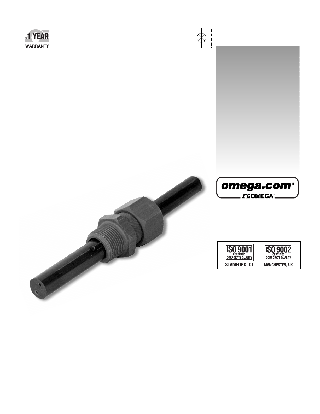
CDE-600/610
Conductivity Cells
Page 2

OMEGAnet®Online Service Internet e-mail
omega.com info@omega.com
Servicing North America:
U.S.A.: One Omega Drive, P.O. Box 4047
ISO 9001 Certified Stamford, CT 06907-0047
TEL: (203) 359-1660 FAX: (203) 359-7700
e-mail: info@omega.com
Canada: 976 Bergar
Laval (Quebec) H7L 5A1, Canada
TEL: (514) 856-6928 FAX: (514) 856-6886
e-mail: info@omega.ca
For immediate technical or application assistance:
U.S.A. and Canada: Sales Service: 1-800-826-6342 / 1-800-TC-OMEGA
Customer Service: 1-800-622-2378 / 1-800-622-BEST
Engineering Service: 1-800-872-9436 / 1-800-USA-WHEN
TELEX: 996404 EASYLINK: 62968934 CABLE: OMEGA
Mexico: En Espan˜ ol: (001) 203-359-7803 e-mail: espanol@omega.com
FAX: (001) 203-359-7807 info@omega.com.mx
®
®
®
Servicing Europe:
Benelux: Postbus 8034, 1180 LA Amstelveen, The Netherlands
TEL: +31 (0)20 3472121 FAX: +31 (0)20 6434643
Toll Free in Benelux: 0800 0993344
e-mail: sales@omegaeng.nl
Czech Republic: Frystatska 184, 733 01 Karviná, Czech Republic
TEL: +420 (0)59 6311899 FAX: +420 (0)59 6311114
Toll Free: 0800-1-66342 e-mail: info@omegashop.cz
France: 11, rue Jacques Cartier, 78280 Guyancourt, France
TEL: +33 (0)1 61 37 2900 FAX: +33 (0)1 30 57 5427
Toll Free in France: 0800 466 342
e-mail: sales@omega.fr
Germany/Austria: Daimlerstrasse 26, D-75392 Deckenpfronn, Germany
TEL: +49 (0)7056 9398-0 FAX: +49 (0)7056 9398-29
Toll Free in Germany: 0800 639 7678
e-mail: info@omega.de
United Kingdom: One Omega Drive, River Bend Technology Centre
ISO 9002 Certified Northbank, Irlam, Manchester
M44 5BD United Kingdom
TEL: +44 (0)161 777 6611 FAX: +44 (0)161 777 6622
Toll Free in United Kingdom: 0800-488-488
e-mail: sales@omega.co.uk
It is the policy of OMEGA Engineering, Inc. to comply with all worldwide safety and EMC/EMI
regulations that apply. OMEGA is constantly pursuing certification of its products to the European New
Approach Directives. OMEGA will add the CE mark to every appropriate device upon certification.
The information contained in this document is believed to be correct, but OMEGA accepts no liability for any
errors it contains, and reserves the right to alter specifications without notice.
WARNING: These products are not designed for use in, and should not be used for, human applications.
Page 3

TABLE OF CONTENTS
1.0 GENERAL INFORMATION .....................................................................................2
1.1 Introduction............................................................................................................................................ 2
1.2 Cautions To Be Observed .................................................................................................................... 2
2.0 SPECIFICATIONS ................................................................................................... 3
3.0 PRINCIPLE OF OPERATION..................................................................................4
4.0 INSTALLATION.......................................................................................................5
4.1 Installation of Flow-Through Sensors................................................................................................. 5
4.2 Installation of Submersion Sensor...................................................................................................... 5
4.3 Electrical Connection............................................................................................................................ 6
5.0 CLEANING THE SENSOR ......................................................................................7
6.0 TROUBLESHOOTING AND SERVICE ...................................................................7
7.0 DRAWINGS .............................................................................................................8
7.1 N106-157 CDE-600/610 SERIES CONTACTING CONDUCTIVITY CELLS ......................................... 8
7.2 N105-134 INSTALLATION OF CDE-600/610 SERIES CONTACTING CONDUCTIVITY CELLS..... 9
7.3 N105-135 ASSEMBLY OF CDE-600/610 SERIES CONTACTING CONDUCTIVITY CELLS
COMPRESSION FITTING ....................................................................................................................10
Page 1
Page 4

CDE-600/610 SERIES CONDUCTIVITY CELLS
INSTRUCTION MANUAL
1.0 GENERAL INFORMATION
1.1 Introduction
1.1.1 This manual provides information on CDE-600/610 Series flow-through and
submersion sensors. Conductivity sensors have long been called cells. The two
terms, cell and sensor, are used interchangeably in this manual.
1.2 Cautions To Be Observed
1.2.1 Consult the factory before using sensor in extremely strong solvents such as
ethylene dichloride. Also, do not exceed the sensor’s maximum ratings listed in
Section 2 of this manual.
1.2.2 Before placing sensor into service, remove protective plastic cap.
1.2.3 Do not exceed the maximum sensor-to-analyzer distance specified for the analyzer
you are using.
1.2.4 Be sure the cell constant is appropriate for the scaling of the analyzer. The constant
is given in the numerical part of the model number. For example, CDE-600-001 has
a constant of 0.01; CDE-600-1 has a constant of 1.
Page 2
Page 5

2.0 SPECIFICATIONS
CELL CONSTANTS: 0.01 to 50
THREADED SIZE: 3/4” NPT
TEMPERATURE COMPENSATION: Automatic 0-120°C (32-248°F)
CABLE LENGTH: 4m (13ft)
INSERTION LENGTH: Variable (see Section 4.1.5)
WETTED MATERIALS:
CDE-600: Graphite, Epoxy, EPDM, CPVC
CDE-610: Graphite, Epoxy, Polypropylene, 316 stainless steel
SAFETY FEATURE: Shoulder on cells provides an integral
safety stop
TEMPERATURE and PRESSURE:
Max. Press. (psi) Max. Temp. (°C)
Type
CDE-600
CDE-610
50
100
150
250
60
50
20
120
Page 3
Page 6

3.0 PRINCIPLE OF OPERATION
3.1 All solutions containing water conduct electricity to some extent. The ability of the solution to
conduct electricity is called “conductance” (the reciprocal of resistance). Addition of
electrolytes such as salts, acids, or bases to pure water will increase the ability of the liquid
to conduct electricity and hence, increase the solution’s conductance (decreases the
resistance).
3.2 An electrolytic conductivity system measures solution conductance by using an analyzer
interconnected with cable to a sensor immersed in the solution. The conductivity sensor is
composed of two or more electrodes and a temperature sensor. The electrodes are in
contact with the solution. The analyzer circuitry impresses an alternating voltage between
the electrodes and the magnitude of the resulting current is linearly related to the solution
conductivity.
3.3 When the temperature of a solution changes, its conductivity changes. The temperature
change is compensated with a thermistor (temperature sensitive resistor) in the conductivity
sensor to alter the gain of the measuring circuit. This is accomplished such that, regardless
of actual solution temperature, the instrument display indicates what the solution
conductivity would be if the solution temperature was 25°C (an internationally accepted
reference).
Page 4
Page 7

4.0 INSTALLATION
4.1 Installation of Flow-Through Sensors
Refer to Dwg# N105-134
4.1.1 Flow-through sensors are secured with the supplied compression fitting. The
insertion length is adjustable within the limits shown in DWG# N106-157. If your
sensor has a cross hole it must be inserted far enough to be sure the cross hole is
in the solution. Use thread sealant such as Teflon tape on the sensor and the
mounting hardware threads.
4.1.2 Install a 3/4” NPT tee into the process line. Tee material should be compatible with
sensor materials of construction for best chemical resistance and
pressure/temperature ratings. A 1” NPT tee with a 1x3/4” reducer may also be
used.
4.1.3 Electrically connect sensor to the instrument as described in Section 4.3.
4.1.4 Remove the protective cap from the sensor and calibrate the system as described
in the instrument operating instruction manual before installing sensor into the
mounting tee.
4.1.5 Screw sensor and fitting into the tee. Locate end
sensor at the approximate center of the stream.
If you disassembled the cell be sure to re-assemble the components as shown in DWG#
N105-135
4.2 Installation of Submersion Sensor
Refer to Dwg# N105-134
4.2.1 Run the sensor cable through the desired length of 3/4” CPVC pipe and screw on
the cell using a thread sealant to keep the cable end of the sensor dry.
4.2.2 Electrically connect the sensor to the instrument as described in Section 4.3.
4.2.3 Remove the protective cap from the sensor and calibrate the system as described
in the instrument’s operating instruction manual before installing sensor in the tank.
4.2.4 Place the cell in the liquid and secure to the tank in an appropriate manner.
of the sensor or cross hole in
Page 5
Page 8

4.3 Electrical Connection
The sensor is electrically connected directly to the instrument or indirectly with a junction
box and interconnect cable. A suitable junction box with a terminal strip is available from
OMEGA (PHE-600-JB).
4.3.1 Direct Hook-Up
A. Route sensor cable to instrument.
B. Connect sensor cable lead wires in accordance with instrument hook-up
diagram.
Note: If you are using this conductivity cell with an OMEGA instrument, connect the four
wires to the cell terminals, matching the colors.
If you are using it with an instrument, which accepts 3 wires, connect as follows:
- Join the black wire and green wire together and connect to the black terminal.
- Connect the red and the white as usual to their respective terminals. CAUTION:
If connecting to a GLI instrument, reverse the red and white wires.
- The shield is not required so there will be no connection to the SHEILD
terminal.
4.3.2 Indirect Hook-Up with Junction Box
A. Mount junction box with terminal strip (PHE-600-JB) on flat surface such that its
cover is removable when installed.
B. Route sensor cable to junction box. Keep terminal strip dry to prevent problems
caused by wet and/or corroded terminals.
C. Route interconnect cable to junction box and instrument. It is recommended
that this cable be run in 1/2” metal conduit for protection against moisture and
mechanical damage.
Do not run line power in the same conduit with interconnect cable because
“electrical noise” may interfere with the sensor signal.
D. Connect sensor and interconnect cable lead wires by matching colours to the
junction box terminal strip. Fasten cover onto junction box.
E. Connect interconnect cable lead wires to instrument in accordance with
instrument hook-up diagram.
4.3.2 Wire Designations
White / Black: Electrodes
Red / Green: Thermistor (Temperature compensation)
Page 6
Page 9

5.0 CLEANING THE SENSOR
5.1 Wipe the electrodes end with a soft cloth and rinse with clean water.
5.2 Clean the sensor electrodes in a soap solution using a soft cloth, brush, Q-tip or pipe
cleaner. If soap solution cleaning is unsuccessful, place the sensor electrode in 10% HCl
(hydrochloric acid) for 1 to 5 minutes to remove the contaminants that are acid soluble. Acid
clean only if absolutely necessary. Never use abrasive cleaners on the sensor or its
electrodes.
6.0 TROUBLESHOOTING AND SERVICE
6.1 Use the troubleshooting section in the analyzer instruction manual to determine whether the
sensor or analyzer is defective.
Page 7
Page 10

Page 11

Page 12

Page 13

WARRANTY/DISCLAIMER
OMEGA ENGINEERING, INC. warrants this unit to be free of defects in materials and workmanship for a
period of
grace period to the normal
ensures that OMEGA’s customers receive maximum coverage on each product.
If the unit malfunctions, it must be returned to the factory for evaluation. OMEGA’s Customer Service
Department will issue an Authorized Return (AR) number immediately upon phone or written request.
Upon examination by OMEGA, if the unit is found to be defective, it will be repaired or replaced at no
charge. OMEGA’s WARRANTY does not apply to defects resulting from any action of the purchaser,
including but not limited to mishandling, improper interfacing, operation outside of design limits,
improper repair, or unauthorized modification. This WARRANTY is VOID if the unit shows evidence of
having been tampered with or shows evidence of having been damaged as a result of excessive corrosion;
or current, heat, moisture or vibration; improper specification; misapplication; misuse or other operating
conditions outside of OMEGA’s control. Components in which wear is not warranted, include but are not
limited to contact points, fuses, and triacs.
OMEGA is pleased to offer suggestions on the use of its various products. However,
OMEGA neither assumes responsibility for any omissions or errors nor assumes liability for any
damages that result from the use of its products in accordance with information provided by
OMEGA, either verbal or written. OMEGA warrants only that the parts manufactured by the
company will be as specified and free of defects. OMEGA MAKES NO OTHER WARRANTIES OR
REPRESENTATIONS OF ANY KIND WHATSOEVER, EXPRESSED OR IMPLIED, EXCEPT THAT OF
TITLE, AND ALL IMPLIED WARRANTIES INCLUDING ANY WARRANTY OF MERCHANTABILITY
AND FITNESS FOR A PARTICULAR PURPOSE ARE HEREBY DISCLAIMED. LIMITATION OF
LIABILITY: The remedies of purchaser set forth herein are exclusive, and the total liability of
OMEGA with respect to this order, whether based on contract, warranty, negligence,
indemnification, strict liability or otherwise, shall not exceed the purchase price of the
component upon which liability is based. In no event shall OMEGA be liable for
consequential, incidental or special damages.
CONDITIONS: Equipment sold by OMEGA is not intended to be used, nor shall it be used: (1) as a “Basic
Component” under 10 CFR 21 (NRC), used in or with any nuclear installation or activity; or (2) in medical
applications or used on humans. Should any Product(s) be used in or with any nuclear installation or
activity, medical application, used on humans, or misused in any way, OMEGA assumes no responsibility
as set forth in our basic WARRANTY/DISCLAIMER language, and, additionally, purchaser will indemnify
OMEGA and hold OMEGA harmless from any liability or damage whatsoever arising out of the use of the
Product(s) in such a manner.
13 months from date of purchase. OMEGA’s WARRANTY adds an additional one (1) month
one (1) year product warranty to cover handling and shipping time. This
RETURN REQUESTS/INQUIRIES
Direct all warranty and repair requests/inquiries to the OMEGA Customer Service Department. BEFORE
RETURNING ANY PRODUCT(S) TO OMEGA, PURCHASER MUST OBTAIN AN AUTHORIZED RETURN
(AR) NUMBER FROM OMEGA’S CUSTOMER SERVICE DEPARTMENT (IN ORDER TO AVOID
PROCESSING DELAYS). The assigned AR number should then be marked on the outside of the return
package and on any correspondence.
The purchaser is responsible for shipping charges, freight, insurance and proper packaging to prevent
breakage in transit.
FOR
WARRANTY RETURNS, please have the
following information available BEFORE
contacting OMEGA:
1. Purchase Order number under which the product
was PURCHASED,
2. Model and serial number of the product under
warranty, and
3. Repair instructions and/or specific problems
relative to the product.
OMEGA’s policy is to make running changes, not model changes, whenever an improvement is possible. This affords
our customers the latest in technology and engineering.
OMEGA is a registered trademark of OMEGA ENGINEERING, INC.
© Copyright 2005 OMEGA ENGINEERING, INC. All rights reserved. This document may not be copied, photocopied,
reproduced, translated, or reduced to any electronic medium or machine-readable form, in whole or in part, without the
prior written consent of OMEGA ENGINEERING, INC.
FOR NON-WARRANTY REPAIRS,
for current repair charges. Have the following
information available BEFORE contacting OMEGA:
1. Purchase Order number to cover the COST
of the repair,
2. Model and serial number of the product, and
3. Repair instructions and/or specific problems
relative to the product.
consult OMEGA
Page 14

Where Do I Find Everything I Need for
Process Measurement and Control?
OMEGA…Of Course!
Shop online at omega.com
TEMPERATURE
MU
Thermocouple, RTD & Thermistor Probes, Connectors, Panels & Assemblies
MU
Wire: Thermocouple, RTD & Thermistor
MU
Calibrators & Ice Point References
MU
Recorders, Controllers & Process Monitors
MU
Infrared Pyrometers
PRESSURE, STRAIN AND FORCE
MU
Transducers & Strain Gages
MU
Load Cells & Pressure Gages
MU
Displacement Transducers
MU
Instrumentation & Accessories
FLOW/LEVEL
MU
Rotameters, Gas Mass Flowmeters & Flow Computers
MU
Air Velocity Indicators
MU
Turbine/Paddlewheel Systems
MU
Totalizers & Batch Controllers
pH/CONDUCTIVITY
MU
pH Electrodes, Testers & Accessories
MU
Benchtop/Laboratory Meters
MU
Controllers, Calibrators, Simulators & Pumps
MU
Industrial pH & Conductivity Equipment
DATA ACQUISITION
MU
Data Acquisition & Engineering Software
MU
Communications-Based Acquisition Systems
MU
Plug-in Cards for Apple, IBM & Compatibles
MU
Datalogging Systems
MU
Recorders, Printers & Plotters
HEATERS
MU
Heating Cable
MU
Cartridge & Strip Heaters
MU
Immersion & Band Heaters
MU
Flexible Heaters
MU
Laboratory Heaters
ENVIRONMENTAL
MONITORING AND CONTROL
MU
Metering & Control Instrumentation
MU
Refractometers
MU
Pumps & Tubing
MU
Air, Soil & Water Monitors
MU
Industrial Water & Wastewater Treatment
MU
pH, Conductivity & Dissolved Oxygen Instruments
M4179/0805
 Loading...