

Page 1
T
PRODUCT INSTRUCTION SHEET
CDE-45T1 and CDE-45T3 Toroidal Conductivity Sensors
Introduction
®
®
Modern conductivity measurement devices include a class of
sensors which use an electrodeless system to determine the
conductivity of a fluid. Electrodeless probes function by first
exciting a toroid with an AC voltage to produce a magnetic
flux in the core. This flux then produces an alternating current
flow in the fluid, which passes as a loop through the center of
the core. A second toroid then acts as a sensor by using the
fluid’s current to produce a magnetic flux in its core which,
in turn creates current flow in its windings. The current flow
in the fluid and subsequently the detector toroid’s windings,
depends on the conductivity of the solution, thereby giving an
accurate measurement without contacting the fluid directly.
Your Electrodeless Conductivity Sensor provides a very linear
voltage output signal versus the conductivity of the solution
within which it is placed. The overall output is proportional to
the excitation signal driven into the driver toroid, the amount
of gain provided by the output signal amplifier, and the
conductivity of the medium being measured. Thus, calibration must be done with a known conductivity solution and the
electronics.
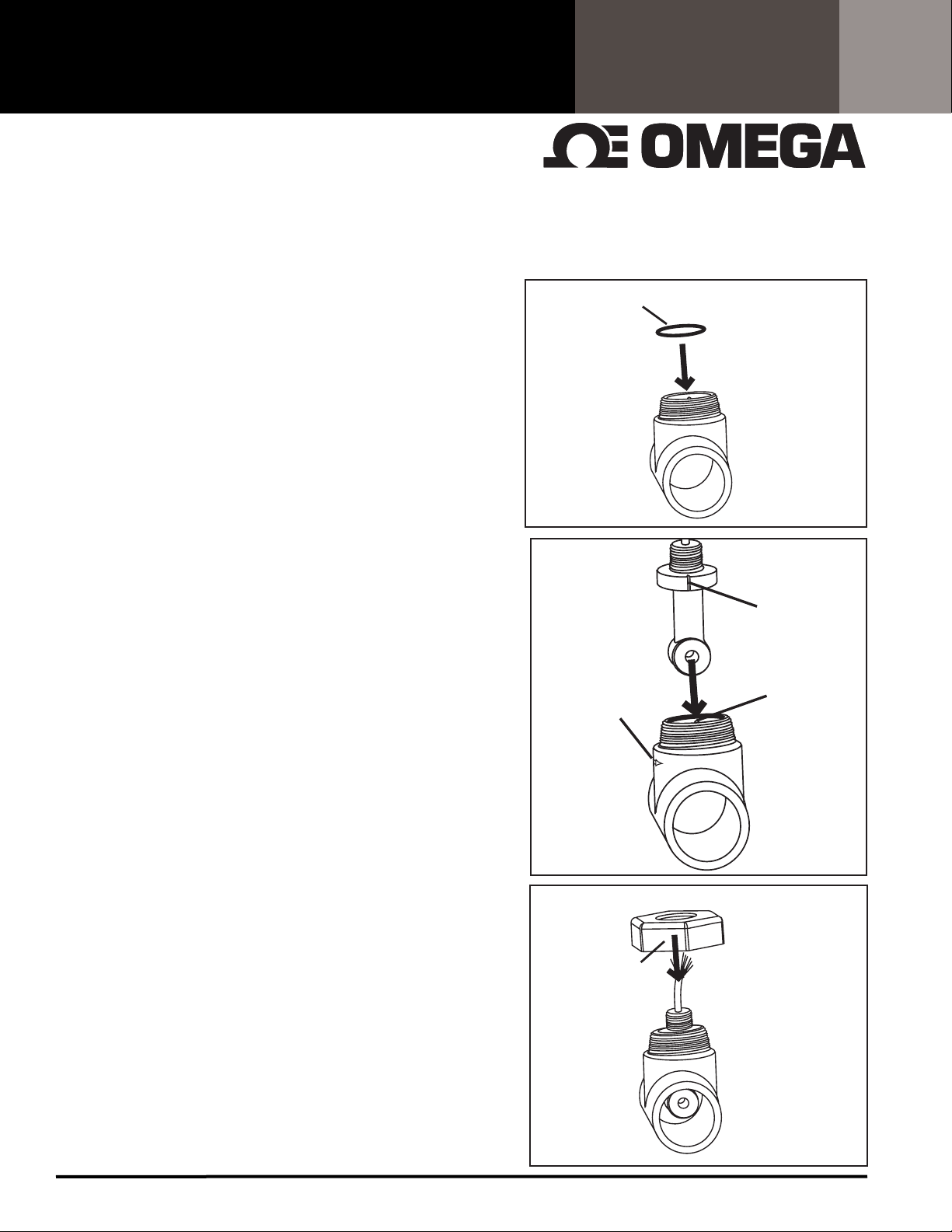
Mechanical Installation
Your toroidal sensor can be installed in 2 ways:
FIG. 1
FIG. 1
FIG. 2
O-RING
SEAL
FLOW DIRECTION
ARROWS x 2
OWARD SENSOR
ALIGNMENT TAB)
(POINT
SENSOR
ALIGNMENT
NOTCH
SENSOR
ALIGNMENT
TAB
1. Submersion mount: Mount sensor into rigid or flexible
conduit using a 3/4" NPT coupling and attaching to the 3/4"
NPT threads near the sensor's cable. Be sure to seal conduit to
avoid fluid build up in conduit.
2. In-Line mount:
a. Plumb flow cell CDTX-45T-PT into line. Flow cell is provided
FIG. 3
with 2" slip fittings. For threaded connection install a 2" slip x
NPT female adapter (CPVC SCH 80).
b. Install o-ring into CDTX-45T-PT as shown in FIG. 1
NUT
c. Install CD-45T1 toroidal sensor into CDTX-45T-PT. Match
notch on flange of sensor with tab of flow cell as show in FIG. 2.
d. Install nut onto threads of flow cell and turn clockwise. DO
NOT USE TEFLON TAPE OR SEALANT ON THREADS!
CDE-45 Page 1 of 4
Page 2
PRODUCT INSTRUCTION SHEET
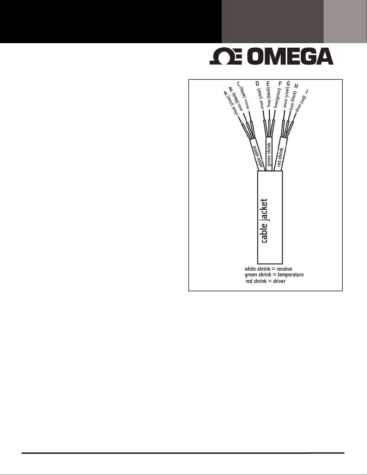
Sensor Wiring
®
The probe has 9 total leads (see FIG. 4).
The driver toroid is connected to the red and black leads with
the red shrink tubing around them. When using the probe
with various controllers, it is important that the red lead be
connected to an AC DRIVER or VOLTAGE IN position while the
black lead is connected to a GROUND or DRIVER RETURN line.
The detector toroid is connected to the white and black leads
with the white shrink tubing around them. The white lead is
typically connected to the SIGNAL IN location and the black
lead is connected to a GROUND or SIGNAL RETURN line.
The temperature element is connected to the green and black
leads with the green shrink tubing around them. Connect
these to the TEMPERATURE INPUT locations. The polarity is not
important.
The 3 bare leads, which supply individual pair shielding
throughout the cable, should typically be connected to a
ground or drain line. Note: The shield leads are not connected
to one another, they are all individual shields for the three
bundles of wires.
Refer to your controller manual for specific wiring details.
FIG. 4
CDE-45T1
Cable Considerations
The cable uses PVC to protect the wires during use. If the cable
comes in contact with the working fluid, the temperature and
pressure ratings must be adjusted to allow for the lower temperature limits of the cable.
C (DRY) but should only be subjected to 70 deg C when immersed in a fluid.
by liquid (raising the possibility of shorting) and all attempts
should be made to keep the cable out of the fluid environment. Do not run cable in the same conduit with any other A.C.
power wiring nor routed close to any high current demanding
equipment. Seal conduit to avoid build-up of moisture. Do not
cut cable. Shorter or longer cables can be provided.
The jacket becomes significantly weakened
The cable can withstand 105 deg
CDE-45 Page 2 of 4
Page 3

)
PRODUCT INSTRUCTION SHEET
Sensor Calibration
®
After the sensor is properly connected, the system should
be calibrated. The typical calibration procedure uses a “low”
and a “high” known standard conductivity solution. The "low"
solution is often DI water or air and is used to calibrate the
zero point of the controller. Plotting these two points will create a straight line, which can be used to find the conductivity
valueof any solution in the range. Make sure probe is immersed in the calibration fluid such that the toroids are totally
submerged. A sample plot is provided in FIG. 5 to show the
approximate values, which will be encountered during calibration.
Note: The values in the plot are arbitrary, each probe will
require unique linear equation values.
If the sensor is to be used in a submersion application, calibrate the sensor in a large glass or plastic beaker with all sides
of the sensor at least one inch away from the wall
(FIG. 6). If the production installation is a pipe (plastic or metal),
calibration should be performed in a similar pipe arrangement.
All Electrodeless (Toroidal) sensors have a wall effect, which
must be taken into account during calibration. If the non-conductive (plastic) wall is within 1 inch of the sensor, the sensor’s
reading will be reduced due to the insulator interaction with
the current path. If the sensor is within 1 inch of a conductive
(metal) wall, the sensor’s reading will be increased due to the
shorting effect of the conducting wall. These wall effects can
be calibrated out of the system by simulating the application’s
mounting configuration. A plot showing the effects of insulating and conducting walls on the output can be seen in FIG.7.
During calibration and production installation (especially in
a submersion environment), it is important to dislodge any
air bubbles, paying special attention to the center hole of the
toroids. Also make sure toroids are totally covered with fluid
when calibrating (FIG. 6).
Plot of Sensorex DC Output Versus Conventional
FIG. 5
DC Output vs. Conventional Conductivity Meter
20
15
10
(mS)
5
0
Conductivity Meter Output
Conductivity Meter Output
123
Sensorex Output (V)
FIG. 6
> 1”
> 1”
Series1
Linear (Series1
y = 6.0498x - 5.435
2
= 1
R
Liquid must totally
cover toroids (be
above this line)
Please refer to your controller's manual for specific calibration
instructions.
Sensor Maintenance
The major advantage of the Electrodeless (Toroidal) Sensor
is almost no maintenance is required. The only maintenance
required during normal operational life of the sensor is to
prevent the toroidal opening from being plugged with debris.
Use a soft brush or rag to remove any debris in the core opening. If that does not work, try a mild detergent or weak acid
(5-10% HCl).
Plot of Normalized Output as a Function of Probe
FIG. 7
2.55
2.5
2.45
2.4
2.35
2.3
2.25
2.2
Normalized Output (V/V)
2.15
024681012
Distance from Wall
Wall Distance (In)
CDE-45 Page 3 of 4
Conducting wall
Insulating Wall
Page 4

PRODUCT INSTRUCTION SHEET
®
Sensor Troubleshooting
If your sensor is not reading as expected check resistance of
leads as shown in FIG. 8. Check temperature leads as shown in
FiG 9.
Sensor Specifications
Installation Type: Submersion via 3/4" NPT or in-line
via CDTX-45T-PT flow cell
Conductivity Range: 500-2,000,000 uS
Maximum Temperature:
Electrode:: 105 deg C
Flow cell: 100C
Cable:: 105 deg C (Dry)
70 deg C (wet)
Maximum Pressure: 100 psig
Wetted Materials:
Sensor: Polypropylene (black)
Flow cell: CPVC
O-ring: Viton
Temperature Compensation: via Pt1000 RTD
FIG. 8
SHRINK COLOR WIRE COLOR RESISTANCE
RED RED
1 TO 2 MEGOHMS
RED BLACK
>20 MEGOHMS (OPEN)
RED CLEAR
WHITE WHITE
1 TO 2 MEGOHMS
WHITE BLACK
> 20 MEGOHMS (OPEN)
WHITE CLEAR
GREEN GREEN
109 or 1090 OHMS**
GREEN BLACK
< 2 OHMS
GREEN CLEAR
0.5
0.5
>20 MEGOHMS (OPEN)
FIG. 9
RTD TYPE TEMP. (deg C/deg F) RESISTANCE(Ohms)
1000Ohm RTD 18/64.4 1069
1000 Ohm RTD 19/66.2 1073
1000Ohm RTD 20/68 1077
1000 Ohm RTD 21/69.8 1081
1000 Ohm RTD 22/71.6 1084
1000 Ohm RTD 23/73.4 1089
1000 Ohm RTD 24/75.2 1092
1000 Ohm RTD 25/77.0 1096
1000 Ohm RTD 26/78.8 1100
1000 Ohm RTD 27/80.6 1104
* * *
Note: There is approximately 3.9Ohm/ Deg C change for Pt1000RTD.
CDE-45 Page 4 of 4
 Loading...