

Page 1

COMPACT CAL
M-2911
Page 2

Foreword
Note
Trademarks
Revisions
Thank you for purchasing the OMEGA CA100 COMPACT CAL. This User's Manual
contains useful information regarding the instrument's functions and operating
procedures as well as precautions that should be observed during use. To ensure proper
use of the instrument, please read the manual thoroughly before operating it. Keep the
manual in the carrying case for quick reference whenever a question arises.
• The contents of this manual are subject to change without prior notice as a result of
improvements in the instrument's performance and functions.
• Every effort has been made in the preparation of this manual to ensure the accuracy of
its contents. However, should you have any questions or find any errors, please
contact your nearest representative.
• Copying or reproduction of any or all of the contents of this manual without Omega's
permission is strictly prohibited.
• MS-DOS is a registered trademark of Microsoft Corporation.
• Company names and product names which appear in this manual are the trademarks
or registered trademarks of the respective companies.
1st Edition: March 1999
1
Page 3
Conventions Used in This Manual
Type Symbol Meaning
Cautionary note
To avoid injury, death of personnel or
damage to the instrument, the operator must
refer to an explanation in the User's Manual.
Calls attention to a procedure, practice or
condition, which, if not correctly performed,
adhered to, or maintained, could result in
injury or death.
Calls attention to a procedure, practice or
condition, which, if not correctly performed,
adhered to, or maintained, could result in
damage to, or destruction of part of the
product.
Note
Key [ ] key Represents a key on the front panel.
Checking the Contents of the Package
Unpack the box and check the contents. If the product is not the one you ordered, any
item is missing or damage to any item is found, contact the dealer from whom you
purchased the instrument.
Calls attention to information which is
important in the operation of the instrument.
2
Page 4
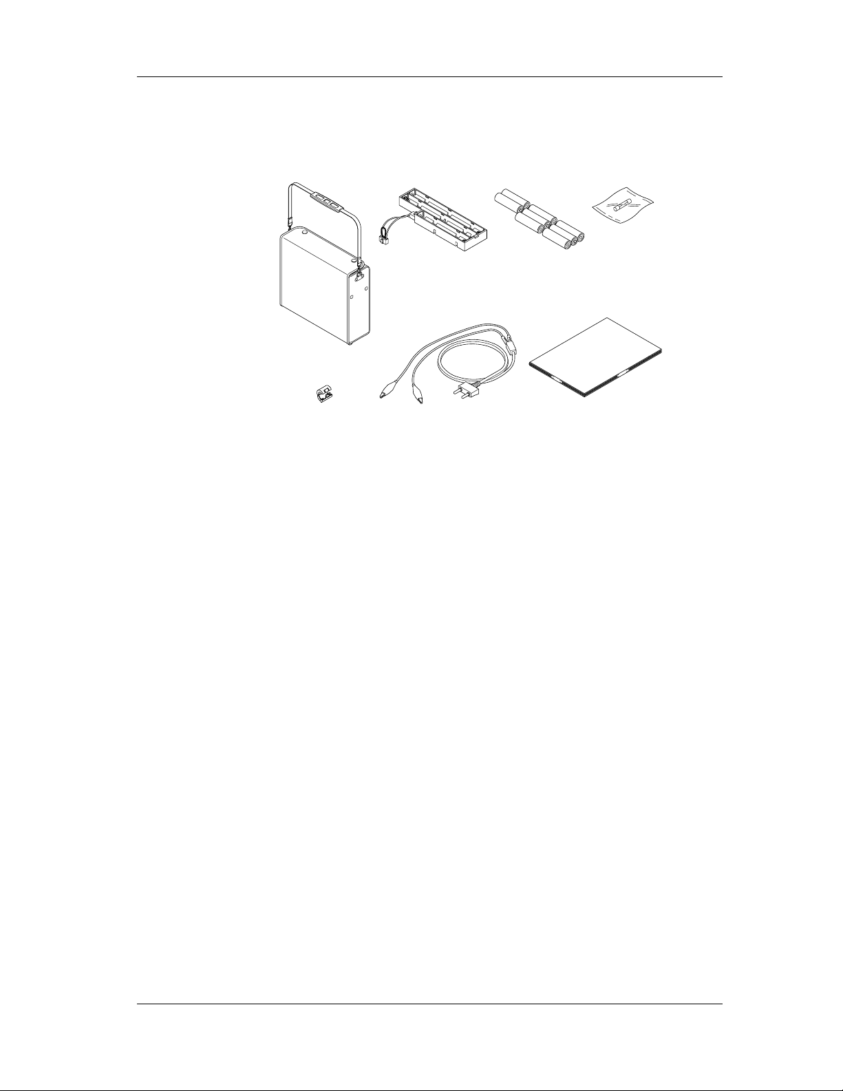
Standard Accessories
Carrying case Battery holder
2 Measurement leads
(CA100-ML)
User's Manual
(M-2911)
8 Alkaline dry cells
2 Ferrite core
(CA100-FC)
Fuse
The following standard accessories are supplied with the instrument. Make sure that all
items are present and undamaged. Note that the dry cell holder (B9914CV) comes
preinstalled in the main unit.
3
Page 5
Safety Precautions
Ths instrument is an IEC safety class I instrument (provided with a terminal for
protective grounding). The following general safety precautions must be observed
during all phases of operation, service and repair of this instrument. If this instrument is
used in a manner not specified in this manual, the protection provided by the instrument
may be impaired. Also, we assume no liability for the customer's failure to comply with
these requirements.
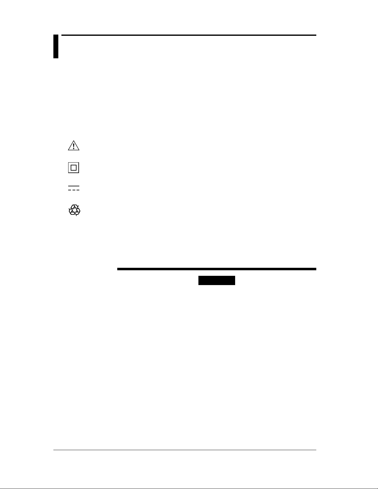
General definitions of safety symbols used on the instrument and in this
manual
To avoid injury, death of personnel or damage to the instrument, the operator must refer
to an explanation in the User's Manual.
This instrument is protected by double insulation.
DC (Direct current)
Ni-Cd
Recycle
Make sure to comply with the following safety precautions. Failure to do so
might result in a fatality or injury to personnel from such hazards as electrical
shock, or damage to the instrument.
WARNING
Prohibition of Using the Instrument in a Gaseous Environment
Do not operate the instrument in the presence of inflammable and
explosive gases or vapors. Operation of the instrument in such an
environment constitutes a safety hazard.
Necessity of Protective Grounding
Never cut off the internal or external protective grounding wire or
disconnect the wiring of protective grounding terminal. Doing so
poses a potential shock hazard.
Defect in Protection Feature
Do not operate the instrument if there is a defect in protective
grounding or fuses. Before commencing operation, always make
sure that the protection feature is fault-free.
External Connection
After making sure that grounding is properly carried out, connect
the protective grounding before connecting to the measurement or
control unit. If you need to touch the circuit, you must turn off the
switch and make sure that no voltage is generated.
4
Page 6

Fuse
To prevent a fire, be sure to use fuses with the specified ratings
(voltage, current, type). Before replacing fuses, turn the power off
and disconnect the power source if you are using an AC power
supply kit. Do not short-circuit the fuse holder.
Removing Covers
There are some areas under high voltage. Do not remove the
cover if the power supply is connected. The cover should be
removed by qualified personnel only.
To use the AC power supply kit (optional) safely, please comply with the
following precautions.
WARNING
Protective Grounding
To prevent electrical shock, be sure to connect the protective
grounding before turning on the power.
Power Cord and Plug
To prevent electrical shock or fire, be sure to use the supplied
power cord. The main power plug can only be plugged in an outlet
with a protective grounding terminal. Do not invalidate protection
by using an extension cord without protective grounding.
Power Supply
Ensure that the source voltage matches the voltage of the power
supply before turning on the power.
5
Page 7

Safety Precautions for Using Ni-Cd Battery
Storage
• Please remove the Ni-Cd batteries from the main unit when storing.
• Do not leave the batteries in a hot-temperature environment such as under direct sun
light, inside an automobile, or near fire, because this leads to leakage of the alkaline
electrolyte.
• For long-term storage (6 months to 2 years), select a location where the humidity is
low and the temperature is in the range from 10 to 25 °C.
• When charging for the first time after long-term storage, deactivation of the reactants
may have led to decreased battery capacity, but this problem is restored after several
cycles of charging and discharging.
• When storing the batteries for more than 6 months, please charge or discharge then
recharge the batteries at least once per year to prevent leakage and the decline of
performance.
Battery Life
The time of operation of the batteries gradually decreases with repeated use, even when
the batteries are fully charged. Though it depends on the condition of use, take 2 years
or 500 times as a measure to have the batteries replaced. (A typical battery life is 2
years or 500 times.) Please also note that prolonged storage leads to shortened battery
life.
Charging
• Do not charge the batteries in any other instrument.
• Only charge batteries that are completely discharged. Charging batteries that are
partially charged results in overcharging. This shortens battery life.
• Avoid overcharging the batteries, because this leads to shortened battery life.
• Charging the batteries for a long time may cause leakage of gases and electrolytes.
WARNING
• Do not disassemble or alter the batteries in any way.
The electrolyte inside the batteries is strong alkaline which can
damage skin and clothes. Be especially careful of the electrolyte
entering the eye, because it may cause blindness.
• Never short the batteries. Heat generated by the batteries may
cause burns.
• Never heat or throw the batteries into fire. The batteries can
rupture or the electrolyte may spray out.
• Never put water on the batteries or immerse them in water.
Such actions can cause heat to be generated or lead to rusting
as well as the loss of ability to function.
• Do not use the batteries in any other instrument. The difference
in the specification can cause damage to the other instrument.
• Do not pull the cable of Ni-Cd battery back or connector with
excessive force.
6
Page 8
Contents
Foreword
Conventions Used in This Manual
Checking the Contents of the Package
Safety Precautions
Components and Their Functions
Block Diagram .......................................................................................................................................... 9
Functions ................................................................................................................................................... 9
Front Panel .............................................................................................................................................. 10
Side Panel ................................................................................................................................................ 12
Rear Panel ............................................................................................................................................... 13
Before Starting Generation or Measurement
Usage Precautions ................................................................................................................................... 14
Installation Conditions ............................................................................................................................ 15
Installing Ferrite Core ............................................................................................................................. 15
Installing Dry Cells ................................................................................................................................. 16
!
Supplying AC Power (Optional) ............................................................................................................. 17
!
Attaching and Charging Optional Ni-Cd Battery Pack ........................................................................... 18
!
Turning the Power Switch On and Off ................................................................................................... 20
Turning Backlighting On and Off ........................................................................................................... 20
Averaging, Key Type, International Temperature, Temperature Unit Settings ...................................... 21
Generation
Connecting the Output Terminal ............................................................................................................. 23
!
Before Generation ................................................................................................................................... 23
DC Voltage, DC Current, Resistance ...................................................................................................... 24
Thermocouple, Resistance Temperature Detector .................................................................................. 26
Frequency, Pulse Signal .......................................................................................................................... 28
Measurement
Connecting the Input Terminal ............................................................................................................... 30
Measuring the DC Voltage, DC Current, and Resistance ....................................................................... 31
24 V DC Power Supply
Connecting the Output Terminal ............................................................................................................. 32
!
Turning Output On and Off .................................................................................................................... 32
Using the RS-232-C Interface
RS-232-C Interface functions ................................................................................................................. 33
Specifications .......................................................................................................................................... 33
Connecting the RS-232-C Interface Cable .............................................................................................. 34
Settings for Communication ................................................................................................................... 35
Before Programming ............................................................................................................................... 39
Using Talk-Only or Printer Mode ........................................................................................................... 39
Troubleshooting
Items to be Checked in the Case of an Abnormality ...............................................................................40
Error Codes and Corrective Actions ....................................................................................................... 40
Maintenance
Calibration ............................................................................................................................................... 41
Replacing the Ni-Cd Batteries ................................................................................................................ 50
Replacing the Backlighting EL ............................................................................................................... 50
Replacing the Fuse .................................................................................................................................. 50
!
7
Page 9

Specifications
Generation Functions .............................................................................................................................. 51
Measurement Function ............................................................................................................................ 53
Generation Section .................................................................................................................................. 54
Measurement Section .............................................................................................................................. 54
24 V DC Supply Section ......................................................................................................................... 54
Communications Function ...................................................................................................................... 54
Common Specifications .......................................................................................................................... 54
External Dimensions ............................................................................................................................... 55
Appendix
Communication Commands .............................................................................................................. App-1
Status Byte Format (for <ESC> command) ...................................................................................... App-5
Output Format of Measured Data ..................................................................................................... App-5
Output Format for Talk-Only or Printer Mode ................................................................................. App-6
Output Format for Setting Information ............................................................................................. App-6
Sample Program ................................................................................................................................ App-7
Index
8
Page 10
Components and Their Functions
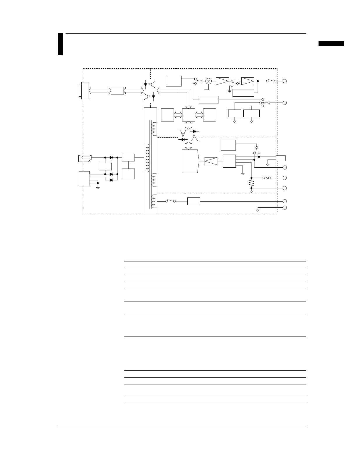
Block Diagram
RS-232-C
Power source/communication part
RS-232-C
driver
Source/CPU part
DC/DC
converter
Display
Reference
voltage
source
CPU
DCV
DCA
Ω
Setting
Current/voltage
conversion
Memory
FRQ
Excess voltage
protection
Current
detection
Ω
DCA
DCV
Excess current
protection
Components and Their Functions
OUT PUT
Hi
SOURCE
Lo
15V DC
BATT.
Functions
Battery
circuit
Constant
current
source
Input
circuit
Shunt resistance
TC
Ω
FUSE
DC/DC
converter
Power
source
control
Measurement
part
24V OUT
AD
converter
Reg.
24V Output part
• Generation Functions
A specified value (in five digits) in function units of voltage, current, resistance,
thermocouple, resistance temperature detector (RTD), frequency, or pulse signal can
be generated.
Function Description
DC voltage Available in three ranges: 100 mV, 1 V, or 10 V
Direct current Available in 20-mA range. SINK function is also available.
Resistance Available in 3 ranges: 500 Ω, 5 kΩ, or 50 kΩ
Thermocouple Thermoelectromotive force can be generated according to the
Resistance temperature detector A resistance can be generated according to the temperature of PT100
Frequency and pulse signal Frequency is in four ranges: 100 Hz, 1000 Hz, 10 kHz, or 50 kHz.
temperature of type K, E, J, T, N, R or B thermocouple.
resistance temperature detector.
Voltage is in the same range as the 10 V range for voltage generation.
Pulse signals with a specified number of bursts (1 to 60000) are
available as well as the above.
R.J.INPUT
Hi
mA MEASURE
Lo
+
24V OUT
-
• Measurement Function
Voltage, current, or resistance can be measured and displayed in 4.5 digits
independent of the generation function.
Function Description
DC voltage Available in three ranges: 500 mV, 5 V, 35 V
Direct current Available in two ranges: 20 mA, 100 mA. An overrange input protection
fuse comes built into the current-input terminal.
Resistance Available in three ranges: 500 Ω, 5 kΩ, or 50 kΩ
9
Page 11
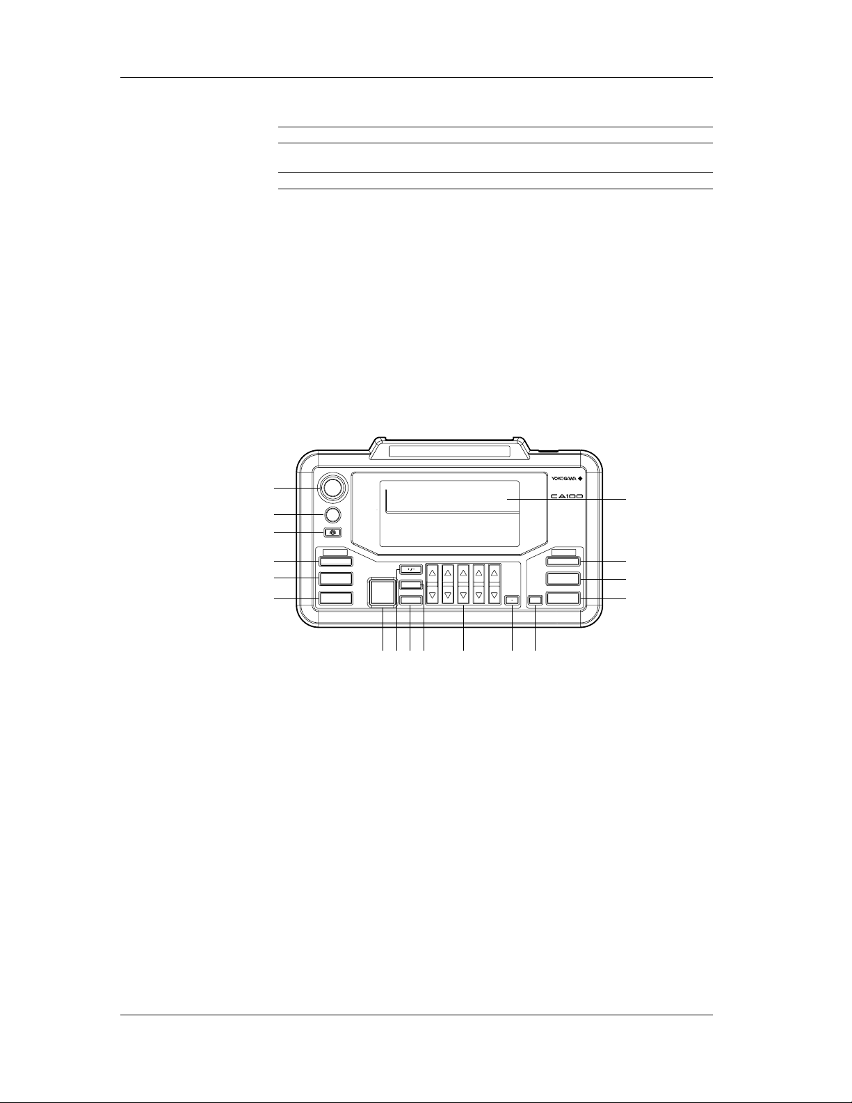
Front Panel
General View
The following functions can be selected:
Function Description
Averaging Displays the results of moving averages of measured data. This is useful if the measured
data are unstable or poor due to noise. (See page 21.)
Display hold Halts updating of the displayed measured value.
• 24 V DC power supply
This is a floating output. Available up to 24 V/22 mA DC max.
• Communications function
Using this function, the instrument can be controlled or measured data can be
transferred to a personal computer via an RS-232-C interface (D-sub 9 pin). This
function also allows the output of setting information or measured data to an ESC/Psupport printer.
• Three-way power supply
Three types of power supply: AA cells, AC adapter (free selection of AC voltages,
optional), and Ni-Cd battery pack (optional) are available.
SOURCE
MEASURE 24V OUT
1
2
3
4
5
6
POWER
CHARGE
SOURCE
24V OUT
FUNCTION
DCV
DCA
Ω Ω
TC
RTD
FRQ
PULSE
SOURCE MEASURE
1
CLR
ZERO
SOURCE
RANGE
ON
ENTER
NEXT
67890
2345
COMPACT CAL
DCV
DCA
MEASURE
ON
FUNCTION
RANGE
HOLD
LCD screen
16
15
14
1312111097 8
1 Power switch
Turns the power on and off.
2 Charging start key
Begins the charging of the Ni-Cd battery pack (optional).
3 Backlight key
Turns backlighting on and off.
Operation keys for generation
4 24 V DC power supply key
Turns the 24 V DC power supply on and off.
5 Function selection key
Selects one of the generation functions: voltage, current, resistance, thermocouple,
RTD, frequency, and pulse.
6 Range selection key
Selects the range for setting generation values. For thermocouple or RTD, selects
TC or RTD type.
10
Page 12
7 Output on and off key
Turns output on and off.
8 +/- key
Toggles the polarity of the output value.
9 NEXT ENTER key
This switches the associated settings when setting the output values for the
frequency and pulse signal. It also fixes the entered value when using the numeric
keypad (refer to the following description).
10 ZERO CLR key
This resets the output value set to zero when using the up/down key (refer to the
following description). When using the numeric keypad (refer to the following
description), the value being entered is canceled and the previous set value is
restored.
11 Output value setting keys
This sets the output value for the generation function. Either of the following two
key modes can be selected from the menu. The up/down key mode is selected as the
factory default setting.
Up/down key: This increments or decrements the values by one count for each digit
corresponding to the [ ]/[ ]. If you try to increment or decrement using this key
with value 9 or 0, the current digit moves up or down by one digit.
Numeric keypad: This enters numbers 0 to 9 directly from the keypad.
12 Decimal point key
This enters the decimal point when using the numeric keypad (refer to the above
description). When this key is pressed, the digits to the left of the decimal point
move to the positions specified on a range basis. When using the up/down key, this
key is unavailable.
Components and Their Functions
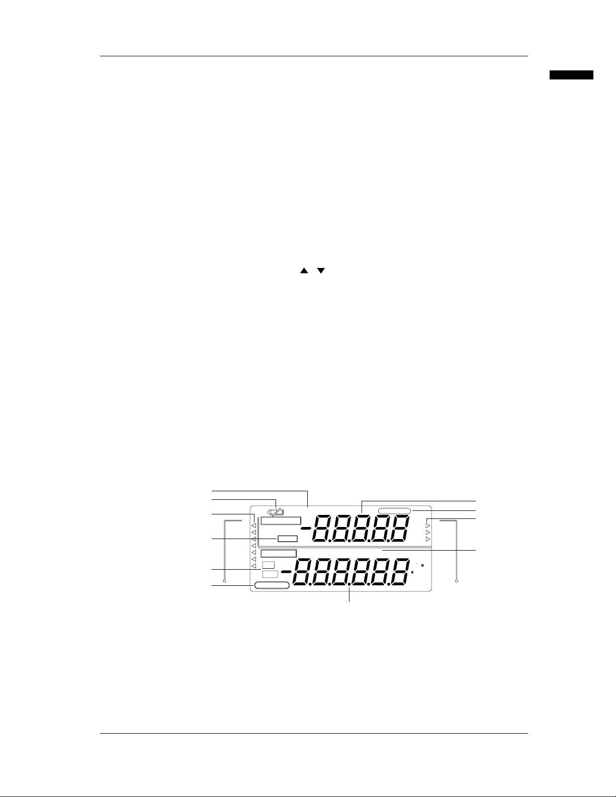
LCD Screen
Operation keys for measurement
13 Display hold key
This retains displayed values as they are.
14 Range selection key
This selects the measurement range.
15 Function selection key
This selects one of the measuring functions: voltage, current, or resistance.
16 Measurement on and off key
This turns measurement on and off.
1
2
3
DCV
4
5
6
DCA
ΩΩ
TC
RTD
FRQ
PULSE
SOURCE
MEASURE
HOLD
SOURCE
ON
OFF
24V OUT
CHARGE END
ITS-90 IPTS-68
INT RJC BRKE JTN
AVERAGE
Pt100
mV
mA
k
Ω
mV
mA
Ω
k C
F
kHz
CYCLES
DCV
DCA
MEASURE
11
10
7
1 State-of-charge indicator
When using Ni-Cd batteries (optional), this indicates its charge status (CHARGE
indicates charging is taking place and CHARGE END indicates charging has
completed).
2 Low-battery indicator
This lights up when the battery becomes weak.
9
8
11
Page 13
3 Generation function indicator
indicates the currently selected generation function. Each press of the
FUNCTION key changes the function from DCV to DCA, Ω, TC, RTD, FRQ, and
PULSE in order.
4 Hold indicator
This indicates the measured value is held.
5 Output on and off indicator
On: indicates the output is turned on.
Off: indicates the output is turned off.
6 24 V DC power supply indicator
This indicates 24 V DC power is being supplied via the 24 V DC output terminal.
7 Generation range and output display
For voltage, current, resistance, frequency, and pulse: This indicates the decimal
place and unit available for setting when selecting a range. Use the up/down key or
numeric keypad to specify a value.
For thermocouple or resistance temperature detector: This indicates the type of TC,
either thermocouple (TC) or resistance temperature detector (RTD), and the
temperature available for setting (e.g., ˚C), when selecting a range.
Use the up/down key or numeric keypad to specify the temperature.
8 International temperature standard display
This displays the international temperature standard currently selected.
9 Measurement function display
displays the measuring function currently selected. Pressing the FUNCTION key
changes the function from DCV to DCA and Ω.
10 Averaging indicator
This indicates that the averaging function is active.
11 Measurement range and measured value display
This indicates the decimal place and unit available for setting when selecting a
range. When the measuring function is activated, the measured value is displayed.
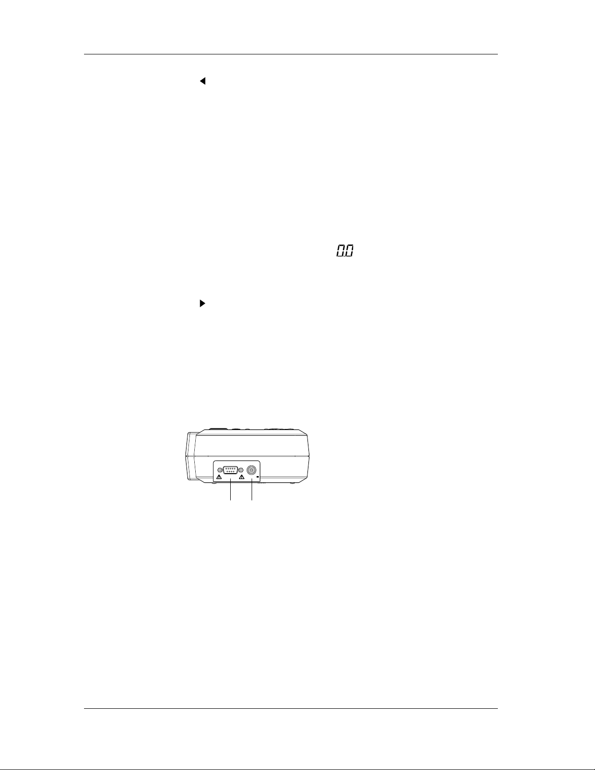
Side Panel
Left side as viewed from the front
The following diagram shows the state when the cover is opened:
1 RS-232-C connector
RS-232-C communication interface connector
2 AC adapter jack (input)
This connects to an optional AC adapter.
Rated input voltage 15 V DC
Maximum rated input current 0.5 A DC
RS-232-C 15V DC
1 2
12
Page 14
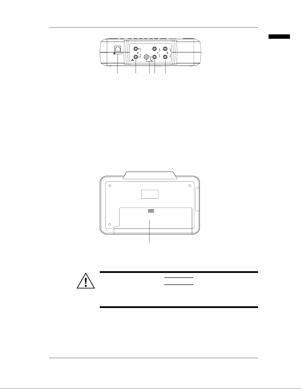
Terminal Side
Rear Panel
MEASURE
R.J. INPUT
24V OUT SOURCE
mA
FUSE
22mA MAX
250V F 125mA
120mA MAX
42V MAX
Lo Lo
ALL TERMINALS 42V
PEAK MAX TO GND.
HiHi
28V
MAX
22mA
1 2 4 53
1 RJC sensor input connector
This connects to an RJC sensor (optional).
2 24 V output terminal
This supplies 24 V DC power.
3 Current input terminal
This is used when measuring current.
4 Voltage/resistance input terminal
This is used when measuring voltage or resistance.
5 Output terminal
This outputs the specified source.
This instrument falls under Overvoltage category II (CAT II). Overvoltage
(installation) category indicates the impulse withstand voltage level which is regulated
by IEC1010-1.
Components and Their Functions
1
1 Battery storage
This holds the attached dry cells or the optional Ni-Cd battery pack.
CAUTION
• Before turning on the power switch, make sure the battery
housing is shut with the cover on properly. Do not open the
cover while the instrument is in operation.
13
Page 15

Before Starting Generation or Measurement
Usage Precautions
Safety Precautions
• Before using this instrument, thoroughly read the "Safety Precautions" on pages 4 and
5.
• Do not remove the cover from the instrument.
Some parts of the instrument use high voltage, which is extremely dangerous. When
the instrument needs an internal inspection or calibration, contact your nearest
representative.
• In case of abnormality
If you notice smoke or the instrument seems to be acting abnormally, for example, it
generates smoke or emits a strange odor, immediately turn the instrument off and, if
an AC power supply kit is in use, disconnect the power cord from the AC outlet. Also
turn off the object connected to the input terminal. If the instrument seems to be
abnormal, contact your nearest reperesentative.
• AC adapter and power cord
Use the dedicated AC adapter. Nothing should be placed on the AC adapter or power
cord; also, it should be kept away from any heat sources. When unplugging the power
cord from the AC outlet, never pull the cord itself. Always hold the plug and pull it. If
the power cord is damaged, contact your dealer. Refer to page 3 for the part number
to use when placing an order.
General Precautions when Handling the Instrument
• When moving the instrument
Turn off the power to the object connected to the instrument. Turn off the power to
this instrument and, if an AC power supply kit is in use, disconnect the power cord
from the AC outlet. When carrying the instrument, always use the carrying case.
• Keep input terminals away from electrically charged articles as they may damage the
internal circuitry.
• Do not allow volatile chemicals to come into contact with the case or operation panel.
Also do not leave them in contact with any rubber or vinyl products for prolonged
periods. The operation panel is made of thermoplastic resin, so take care to avoid
contact with any heated articles such as a soldering iron.
• Before cleaning the case and operation panel, make sure that the power cord is
disconnected from the AC outlet if the AC power supply kit is used. Dampen a clean
soft cloth with water and wipe the surface of the case and panel. Water that gets inside
the instrument may result in breakdown.
• If the AC power supply kit will not be used over a long period, unplug the power cord
from the outlet.
• For handling dry cells, refer to the section, "Installing Dry Cells," on page 16.
• Do not use the instrument with the cover for the battery housing left open.
• Gently wipe the surface with a soft and dry cloth. Do not use chemicals such as
benzene or thinner, because these may cause discoloration and deformation.
• Do not stack the instrument.
14
Page 16
Installation Conditions
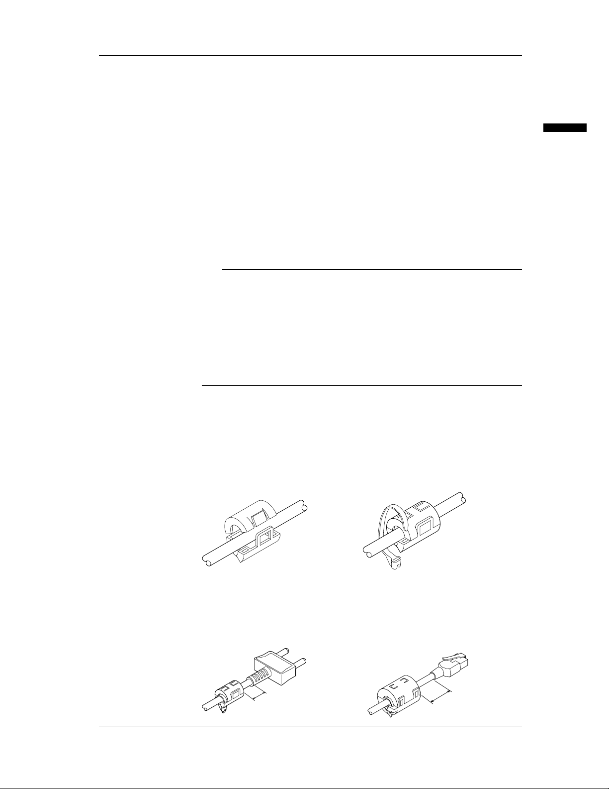
• Guide the cable through the clamp
filter and lock the core.
• Thread the supplied band through
the opening of the clamp filter to
fasten the core, and then cut away
any extra length of the band.
The instrument must be installed in a place where the following conditions are met.
• Ambient temperature and humidity
Ambient temperature: 5 to 40°C (5 to 30°C for charging during generation or
measurement)
Ambient humidity: 20 to 80% RH (no condensation)
• Flat horizontal location
Set the instrument in a level, stable place.
Never install the instrument.:
• In direct sunlight or near sources of heat
• Where the level of mechanical vibration is high
• Near noise sources such as high-voltage equipment or power lines
• Near strong magnetic field sources
• Where an excessive amount of soot, steam, dust or corrosive gases are present.
• In an unstable place
• Where explosions caused by inflammable gases or the like are possible
Note
• To ensure high measurement accuracy, the instrument should be used under the following
conditions:
Ambient temperature: 23 ± 5°C
Ambient humidity: 20 to 80% RH (no condensation)
When using the instrument in temperature ranges of 5 to 18°C or 28 to 40°C, add the temperature
coefficient specified in the "Specifications" on page 51 to the accuracy.
• If the ambient humidity of the installation site is 30% or below, use an anti-static mat to prevent
static electricity.
• Internal condensation may occur if the instrument is moved to another area where both the ambient
temperature and humidity are higher, or if the room temperature changes rapidly. In such cases,
acclimatize the instrument to the new environment for at least one hour before starting operation.
Before Starting Generation or Measurement
Installing Ferrite Core
This instrument is CE Mark compliant. When using the measurement lead, make sure
to attach the accessory clamp filter on it according to the directions indicated below. In
addition, when purchasing the optional measurement lead or RJC sensor, make sure to
purchase the clamp filter also and attach it according to the directions indicated below.
Note that if the clamp filter is not properly attached or used, the standard cannot be
satisfied.
Installation
Installation location
• Measurement lead • RJC sensor connection cable
50 mm or less
50 mm or less
15
Page 17
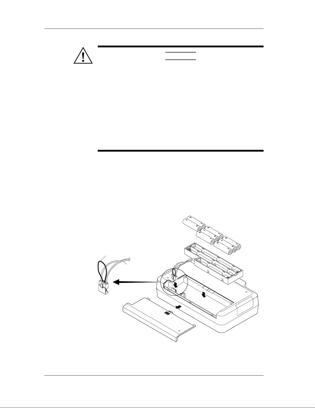
Installing Dry Cells
Installation
CAUTION
When using dry cells, observe the following precautions:
• The use of AA alkaline cells is recommended.
• When inserting a battery, observe the polarity; otherwise, a liquid
spill or explosion may occur.
• Before operating the instrument, make sure that the dry cell
holder is inserted into the body and the back cover is closed.
• Do not disassemble, heat, or throw a battery into a fire.
• Do not short out a cell.
• Do not charge a dry cell.
• Do not solder a line onto a dry cell.
• Use new dry cells from the same manufacturer.
• When dry cells become weak, replace all eight cells with new
ones.
• If the instrument will not be used for a long time, remove the dry
cells.
1 Make sure that the power switch on the front panel is turned off and no AC power
supply kit is connected..
2 Remove the cover of the dry cell storage on the back of the body.
3 Insert the eight dry cells into the dry cell holder. Make sure that they are seated in
the correct indicated direction of polarity (refer to the following diagram).
4 Attach the dry cell holder to the body and push the connector until it hits the bottom
of the receiving side of the body (refer to the following diagram).
5 Reassemble the cover.
16
Strap
Cable
To remove dry cells, pull the strap to unplug the connector from the dry cell storage and
remove the dry cell holder. Do not pull on the cable of the connector.
Page 18
Low-Battery Indicator
If the dry cells become weak, appears in the upper-left of the display. When this
happens, immediately replace the old batteries with new eight alkaline batteries.
Life of Alkaline Batteries
The life of alkaline batteries varies depending on the operating conditions. Refer to the
following table:
Generated Output Measurement 24 V DC Backlight Life (when used
20 mA (with 1 kΩ load) on on on Approx. 2 hours
5 V DC (with 500 Ω load) on off off Approx. 10 hours
Supplying AC Power (Optional)
Connecting the Power Cord
Make sure that you perform the following steps before connecting the power. Failure to
do so may cause electrical shock or cause damage to the instrument.
• Always use protective grounding to prevent electrical shock.
• Since the power cord supplied with the AC power supply kit has
a 3-prong grounded plug, the AC outlet to which the power cord
is to be connected must be a 3-slot grounded terminal.
• Before connecting the power cord, make sure that the power
supply voltage complies with the rated electrical power voltage
for the instrument.
• Before connecting the power cord, make sure that the
instrument's power switch is turned off.
• Never use an extension cord that does not have protective
grounding; otherwise, the protection feature will be negated.
• Do not use any AC power supply other than the power supply kit
(model 366969) from Omega.
Before Starting Generation or Measurement
Function Power Supply continuously)
WARNING
Connecting the AC Power Supply
1 Make sure that the instrument's power switch is turned off.
2 Connect the optional AC adapter to the AC adapter jack.
17
Page 19
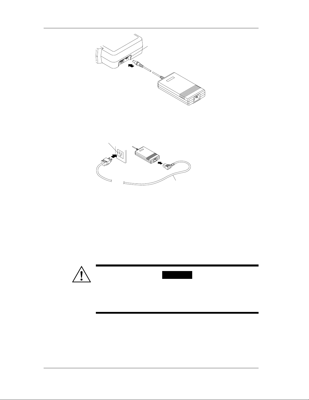
AC adapter jack
AC adapter
3 Connect the power cord included in the AC power supply kit to the AC power
supply adapter.
4 Plug the other end of the power cord into an AC outlet that meets the following
conditions. The AC outlet must be a 3-slot grounded terminal.
3-prong AC outlet
Power cord
Power Rating
Rated supply voltage: 100 to 120 V AC/200 to 240 V AC
Permitted supply voltage range: 90 to 132 V AC/180 to 264 V AC
Rated supply voltage frequency: 50/60 Hz
Permitted supply voltage frequency range: 48 to 62 Hz
Maximum power consumption: 60 VA or below
Rated output voltage for AC adapter: 15 V DC
Maximum rated output current for AC adapter: 1.33 A
Attaching and Charging Optional Ni-Cd Battery Pack
Attaching the Ni-Cd Battery Pack to the Main Unit
To attach the battery pack to the instrument, follow the next procedure:
WARNING
• Before replacing the Ni-Cd battery pack, be sure to turn off the
power switch on the front panel and remove the power cord from
the AC outlet to avoid such possible hazards as short-circuiting
in the battery-charging circuitry.
• Use only an Ni-Cd battery pack from Omega.
18
Page 20
1 Make sure that the power switch on the front panel is turned off.
2 Disconnect the power cord from the AC outlet.
3 Remove the cover of the dry cell storage compartment on the back of the body.
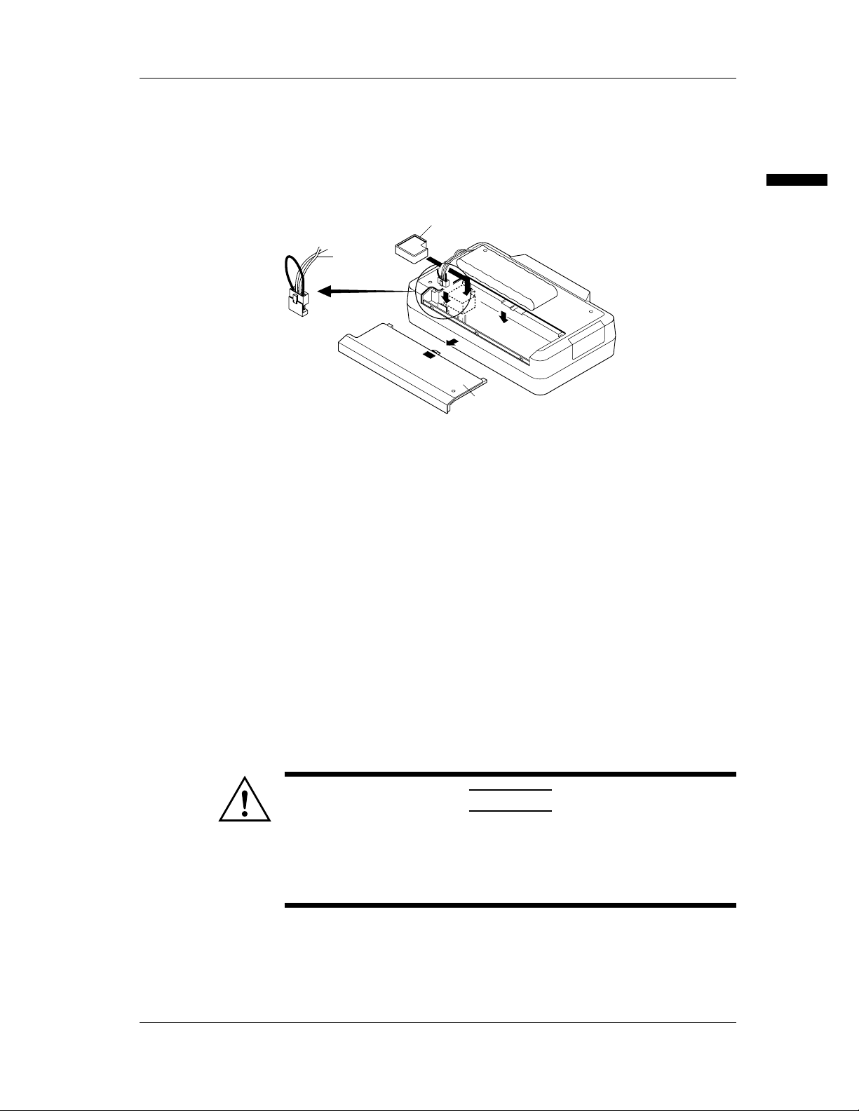
4 Insert the spacer on the cable side of the battery pack.
5 Insert the connector of the attached Ni-Cd battery pack until it hits the bottom of the
receiving side of the body (refer to the following diagram).
6 Reassemble the cover.
When removing the Ni-Cd battery pack, pull the strap to unplug the connector from the
battery housing. Do not pull on the cable of the connector.
Precautions in Charging
• Since an optional Ni-Cd battery pack is not charged prior to shipment, fully charge
the battery pack before operating the instrument for the first time.
• Before charging the battery pack, make sure that it is discharged completely. If
charging is started on a battery which has not been discharged completely or on a
battery for which charging has been stopped halfway through, the life of the battery
pack will be reduced.
• The internal temperature of the instrument rises during charging since the internal
power consumption increases. This may cause a degraded accuracy in generation or
measurement compared with a normal condition. For accuracy, refer to the section,
"Specifications," on page 51.
• This instrument allows charging during generation or measurement operations. In this
case, keep the ambient temperature between 5 to 30°C, or the battery pack will
become extremely degraded.
• If the AC power supply is interrupted during charging, the instrument waits up to
about 30 minutes for restoration of the AC power supply. If the power is not restored
by that time, the instrument aborts the charging sequence and automatically turns off.
It resumes charging of the battery pack if the power is restored within the given time.
Cable
Before Starting Generation or Measurement
Spacer
Be careful of
the direction
of the spacer.
Cover
CAUTION
• Use only the AC power supply kit (model: 366969) from Omega
for charging.
• When charging, keep the instrument horizontal. Make sure that
there is no obstruction around the instrument, so that heat
generated in the instrument is properly dissipated.
19
Page 21

Charging the Battery Pack
1 Supply the instrument with AC power via the method described above.
2 Turn on the power switch.
3 Press the [CHARGE] key.
"CHARGE" is displayed. The instrument then momentarily shows the remaining
time every minute. The battery pack is fully charged in about 10 hours, and
"CHARGE END" is displayed.
4 Turn off the power switch.
5 Disconnect the power cord and the AC adapter from the instrument.
Display Indicating Low Battery
After a certain length of operation has passed and the battery power weakens, "
appears in the upper-left of the screen. When you see this display, immediately charge
the pack.
Guideline for continuous operating time
The operating time of the Ni-Cd battery pack is approximately 7.5 hours when in
continuous use. Refer to the following table:
Generated Output Measurement 24 V DC Backlight Life (when used
Function Power Supply continuously)
20 mA (with 1 kΩ load) on on on Approx. 2.5 hr.
5 V DC (with 500 Ω load) on off off Approx. 7.5 hr.
Turning the Power Switch On and Off
Before Turning On the Power
For driving this instrument, AA dry cells, an AC power supply (optional), or a Ni-Cd
battery pack (optional) is available. Before turning the instrument on, prepare the
intended power supply following the above instructions.
"
Note
Before operating the instrument using dry cells or the Ni-Cd battery pack (i.e., battery driving),
disconnect the power cord and AC adapter. If the AC power source remains connected, the
instrument will operate on the AC power rather than on the batteries.
Turning the Power on and off
Pressing the power switch on the front panel alternates between on and off. When
turning the power switch on, the self-diagnosis function runs, and "OFF" that indicates
the output is turned off and " mV" appear on the lower line of the display.
Automatic Power Off
If the instrument has not received a key operation or sending/receiving request through
the communication interface for approximately 30 minutes, the power supply
automatically turns off. If necessary, turn the power switch back on.
Turning Backlighting On and Off
Backlighting can be turned on so that it is easy to see the screen even if generation/
measurement is done in a dark place. However, this will shorten the life of the batteries
when the instrument is being operated by battery.
1 Press the [ ] key.
2 To turn backlighting off, press the [ ] key again.
20
Page 22

Note
When backlighting the instrument, the internal power consumption increases, and the internal
temperature rises. This may cause a degraded accuracy in generation or measurement compared with
a normal condition. For accuracy, refer to the section, "Specifications," on page 51.
Averaging, Key Type, International Temperature, Temperature Unit Settings
Settings
This instrument allows the setting of Averaging, Key Type, International Temperature,
and Temperature Unit Settings from the maintenance menu.
Averaging setting: This specifies whether to enable (on) or disable (off) the moving
average of the measured data. If the measured data display
fluctuates due to noise, set the averaging setting to on to perform
the moving averages. The setting defaults to off.
Key-type selection: Either the up/down keys (UP-DN) or numeric keypad (TEN) is
available for the output value setting key. The setting defaults to
"UP-DN."
International temperature standard selection: Either of IPTS68 or ITS90 is available for
the international temperature standard. The setting defaults to
"ITS90."
Selection of temperature unit: Either ˚C or ˚F can be selected as the temperature unit.
The default setting is ˚C.
Setting
1 Press the [NEXT ENTER] key and the [ZERO CLR] key at the same time.
[SP FC] and [End] are displayed.
2 Press the [ ] or [ ] key until [End] on the lower line of the display changes to [Set
uP], and then press the [NEXT ENTER] key.
The setup menu is displayed.
Before Starting Generation or Measurement
3 Pressing the [ ] or [ ] key changes the bottom menu from [AVG] to [KEY] and [t
tYPE]. To set the averaging function, display [AVG] and press the [NEXT ENTER]
key.
4 Select [on] or [oFF] using [ ] or [ ] and press the [NEXT ENTER] key.
5 To specify the key type, display [KEY] using [ ] or [ ] and press the [NEXT
ENTER] key.
6 Select [uP-dn] or [tEn] using [ ] or [ ] and press the [NEXT ENTER] key.
7 To set the international temperature standard, display [t tYPE] using [ ] or [ ] and
press the [NEXT ENTER] key.
8 Select the [iPtS68] or [itS90] using the [ ] or [ ] and press the [NEXT ENTER]
key.
9 To set the temperature unit, display [t unit] using the [ ] or [ ] and press the
[NEXT ENTER] key.
10 Select [C] or [F] using the [ ] or [ ] and press the [NEXT ENTER] key.
21
Page 23

11 Press the [ ] to display [Set uP] on the lower line of the display.
12 Press the [ ] or [ ] to display [End] and press the [NEXT ENTER] key.
The measurement/generation screen is returned.
22
Page 24

Generation
SOURCE
Red
Black
Target device
Measurement lead
Hi
Lo
HL
+
-
Clip
g
n
Connecting the Output Terminal
1 Insert the plug of the measurement lead into the output terminal of the instrument.
2 Pinch the terminals on the target device with the clips on the other side of the lead.
Wiring generating resistance or RTD (3-line or 4-line wiring)
The use of optional input-terminal adapters makes it easy to implement 3-line or 4-line
wiring. Input-terminal adapter is an adapter for conversion from safety terminal to
binding post.
Prepare wire rods in stead of the typical measuring lead and connect it as shown in the
following figure (for a three-wire system).
CA100
SOURCE
Hi
Lo
Sense Lo
Generation
Measurin
Instrume
Hi
Lo
Before Generation
CAUTION
• Do not apply voltage to the output terminal except when the
instrument is in the current-generation mode. Otherwise, the
internal circuitry may be damaged.
• Since this instrument is calibrated with the voltage drop of the
measurement lead excluded, an error due to the resistance at
the measurement lead (approx. 0.08 Ω) must be considered.
For accurate generation, be sure to perform auto-zero calibration (i.e., cancel the offset
error) before generation.
Effects of executing auto-zero calibration
• During measurement: The displayed data of measurement are held until the auto-zero
calibration ends, and sampling is also interrupted if applicable.
• When averaging is enabled: The accumulated data for a moving average is discarded,
and a new averaging process starts as the auto-zero calibration ends.
1 Press the [FUNCTION] key on the SOURCE side until [CAL/no] is displayed.
2 Press the [ ] or [ ] key to change the lower display to [YeS].
3 Press the [NEXT ENTER] key to execute auto-zero calibration.
4 After completing auto-zero calibration, the function switches to DCV.
23
Page 25

DC Voltage, DC Current, Resistance
Type
Generation Range
Display Setting Range
DCV
100 mV
1 V
10 V
mV
V
V
-10 to 110 mV
-0.1 to 1.1 V
-1 to 11 V
DCA 20 mA mA 0 to 22 mA
Ω
500 Ω
5 kΩ
50 kΩ
Ω
kΩ
kΩ
0 to 550 Ω
0 to 5.5 kΩ
0 to 55 kΩ
The output terminal generates voltage, current or resistance at the specified value.
1 Press the [FUNCTION] key on the SOURCE side to align with the [DCV],
[DCA], or [Ω] that you want.
2 Press the [RANGE] key on the SOURCE side to select the generation range.
3 To change the polarity, press the [+/-] key.
Selecting "-" places a leading minus sign (-) before figures, while selecting "+"
places no leading sign.
4 Specify the output value.
• Using [ ] or [ ] (for initial setting)
Press [ ] or [ ] to specify the output value from the rightmost digit.
To reset the value to zero, press the [ZERO CLR] key.
• Using the numeric keypad (refer to page 21)
Enter an output value using the numeric keypad and the decimal point key, and
press the [NEXT ENTER]. The figure flickers when entering a value.
When entering decimals, press the decimal point key first and then the
appropriate key or keys on the numeric keypad.
If a value out of the generation range is specified, an error occurs. In this case,
press the [ZERO CLR] to reset to the previous value, and reenter a new value.
5 Press the [SOURCE ON] key to start generation.
[ON] is displayed.
To stop the output, press the [SOURCE ON] key again.
[OFF] is displayed.
[OFF]: Indicates that the relay on the output stage is open.
Voltage generation
CA100
Hi
Voltmeter
Vx Vx
Lo
V
Vx: Specified voltage
24
Current generation
CA100
Hi
Lo
Ix: Specified current
Ix
Ammeter
A
Resistance generation
CA100
Hi
Lo
Ohmmeter
V
Ix
(Constant
current
source)
Ix: Current from the constant current
source (measured current)
Rx:Specified value from this
instrument
Vx: Generated voltage value
represented as Ix*Rx
* This function is unavailable for the
constant voltage source.
Page 26

Note
• When outputting, if you change the generation function, generation range, or polarity (only for
current generation), output turns off automatically.
• The resistance generation of this instrument employs an "active impedance" scheme in order to
provide a dummy resistance. This scheme generates a DC voltage appropriate for the current being
measured that is supplied by a resistance meter such as a multimeter. The scheme, therefore, can
generate correct DC voltages only for the resistance meter used in the measuring method shown in
the figure on the previous page (i.e., the value of the supplied current being measured varies
depending on the range of resistance generation. For further details, see the specifications of
resistance on page 51). Note that connecting a low-impedance device (e.g., a voltage source,
capacitor, or resistor) to the output during resistance generation may cause oscillation.
• In the case of the resistance generation function, it takes 10 ms in a 500 Ω range (refer to the
specifications for other ranges) for the instrument-detected resistance measurement current to
settle within the given accuracy range. This means that the connecting time must be no less than
10 ms where a device that operates by electrically switching its signal input circuit is used.
• Providing any different type of setting with the [ZERO CLR] and [NEXT ENTER] keys during
resistance generation will abort the generation.
• Providing any different type of setting with the [ZERO CLR] and [NEXT ENTER] keys when the
generation function is either TC, RTD, FRQ, or PULSE will change the function to DCV.
Output Limiter
If the load current when generating a voltage of 1 or 10 V range or the load voltage
when generating a current of 20 mA range exceeds the maximum value in the
specifications, the protective limiter turns output off. To recover the output, correct the
load to a normal state and press the [SOURCE ON] key to turn output on.
Current sinking function
This allows drawing the specified value of the current from an external voltage source
in the direction of the Hi terminal.
Generation
CA100
Ix: Specified value of current
Hi
Lo
Ix
To use the function follow the procedure below:
1 Turn off the external power supply (up to 28 V).
2 Connect the external power supply to the output terminal on the instrument.
3 Select [DCA] using the [FUNCTION] key, set the polarity to "-" using [+/-], and
specify the output value.
4 Turn on the external power supply and press the [SOURCE ON] key to turn on
output.
Note
• The current-generation function of the CA100 may result in an unstable output if the CA100 is
connected to a positioner or electro-pneumatic converter having a large input inductance
component. Make sure the input inductance component of the equipment to be connected is no
greater than 100 µH.
• If the equipment’s input inductance component is unknown, connect the CA100 to the equipment
as shown below, and measure the generated current. If the reading does not stabilize or an
accuracy error results at that point, the input inductance component is likely to be greater than
100µH.
CA100
SOURCE
(DC mA)
MEASURE
(DC mA)
Hi
Lo
Lo
mA
Hi
Lo
Input source:
Equipment such as a
converter
• If the equipment’s input inductance component is too large, connect a 200-Ω resistor and a 1-µF
capacitor to the CA100’s output, as shown below. This setup makes it possible to connect an input
having an inductance component of up to 3 H to the CA100.
(This RC circuitry is available as an accessory part numbered 990 20.)
25
Page 27

(99020)
SOURCE
CA100
Note however that this additional circuitry reevaluates the CA100’s response specification as noted
below.
Response: 1 sec (at load resistances no greater than 2 kΩ)
Do not use this circuitry for purposes other than current generation; otherwise, it can produce
measurement errors.
(DC mA)
MEASURE
(DC mA)
R: 200 Ω ±10%, 1/4 W
C: 1 µF ±10%, 50 V
(Equivalent to the 533M5002105K resistor from Matsuo Electric)
Hi
Lo
Lo
mA
Hi
R
C
Lo
Thermocouple, Resistance Temperature Detector
This generates thermo-electric power corresponding to the temperature of thermocouple
(TC) or resistance corresponding to the temperature of resistance temperature detector
(RTD) from the output terminal.
1 Press [FUNCTION] on the SOURCE side and align to [TC] or [RTD].
2 Press [RANGE] on the SOURCE side to select TC type.
Type TC/RTD Type Display Temperature Range
TC
K
Input source:
Equipment such as a
converter
˚C
-200.0 to +1372.0˚C
E
J
T
N
B
R
RTD
* RTD : The specifications are compatible with both IEC 751-1983 and IEC 751-1995.
TC : The specifications are compatible with both IEC 584-1-1989 and IEC 584-1-1995.
To switch the standard, refer to page 21.
Pt100 ˚C -200 to +850˚C
˚C
˚C
˚C
˚C
˚C
˚C
-250.0 to +1000.0˚C
-210.0 to +1200.0˚C
-250.0 to +400.0˚C
-200.0 to +1300.0˚C
+400 to +1820˚C
-40 to +1767˚C
3 To change the polarity, press the [+/-] key.
Selecting "-" places a leading minus sign (-) before figures, while selecting "+"
places no leading sign.
4 Specify the temperature.
• Using [ ] or [ ] (for initial setting)
Press [ ] or [ ] to specify the output value from the rightmost digit.
To reset the value to zero, press the [ZERO CLR] key.
• Using the numeric keypad (refer to page 21)
Enter a temperature value using the numeric keypad and the decimal point key
(where applicable), and press the [NEXT ENTER] key. The figure flickers when
entering a value.
When entering decimals, press the decimal point key first and then the
appropriate key or keys on the numeric keypad.
If a value out of the generation range is specified, an error occurs. In this case,
press [ZERO CLR] to reset to the previous value, and reenter a new value.
5 Press the [SOURCE ON] key to start generation.
[ON] is displayed.
To stop the output, press [SOURCE ON] again.
[OFF] is displayed.
26
Page 28

Note
RJC sensor
With RJC sensor Without RJC sensor
20˚C (798 µV)
813 µV
Generated
voltage
CA100
40˚C
CA100
1611 µV
Generated
voltage
Set temperature
40˚C
Set temperature
• When outputting, if you change the generation function or generation range, output turns off
automatically.
• The generation of RTD-use signals in this instrument employs an "active impedance" scheme in
order to provide a dummy resistance. This scheme generates a DC voltage appropriate for the
current being measured that is supplied by a resistance meter such as a multimeter. The scheme,
therefore, can generate correct DC voltages only when the value of the supplied current being
measured is 1 to 5 mA. Note that connecting a low-impedance device (e.g., a voltage source,
capacitor, or resistor) to the output during resistance generation may cause oscillation.
• In the case of generating RTD-use signals, it takes 10 ms in a 500-Ω range (refer to the
specifications for other ranges) for the instrument-detected resistance measurement current to
settle within the given accuracy range. This means that the connecting time must be no less than
10 ms where a device that operates by electrically switching its signal input circuit is used.
Reference Junction Compensation
Use a reference junction compensation (RJC) sensor (optional) to calibrate a
thermometer containing built-in RJC without using an external 0°C reference junction
chamber.
1 Connect an RJC sensor to the RJC sensor input connector.
When connecting, insert the connector until its upper locking hook snaps into place.
To disconnect the connector, press the hook lightly down to release the lock and
pull it.
Generation
Locking hook
Sensor lead
Note
• Do not pull the sensor lead with the connector locked.
2 Connecting the sensor automatically activates the INT RJC state and thermo-
electric power is output with reference to the temperature detected by the RJC
sensor. [INT RJC] is displayed at this time. (For reference temperature
measurement accuracy using an RJC sensor, refer to the section "Specifications" on
page 52.)
• The thermo-electric power when an RJC sensor is connected can be achieved by
subtracting the thermo-electric power detected by an RJC sensor from the thermoelectric power without an RJC sensor.
27
Page 29

• Compensating the output voltage using the temperature detected with the RJC sensor
is executed on a sampling rate of approximately 10-second intervals. It means that
there is a delay of up to 10 seconds before the first compensation starts.
• To perform accurate measurement, leave the instrument for a certain time (5 min. at
room temperature) before starting the measurement.
Be sure to disconnect the RJC sensor from the instrument when no
reference junction compensation is required.
Frequency, Pulse Signal
This generates frequencies and pulse signals at specified values via the output terminal.
CAUTION
Frequency
Voltage (0 to 10 V)
signal
Frequency (1 Hz to 50 kHz)
Pulse signal
Voltage (0 to 10 V)
Frequency (1 Hz to 50 kHz)
: One pulse
Number of generated pulses
(1 to 60000 cycles)
1 To generate frequencies, press [FUNCTION] on the SOURCE side to align with
[FRQ]. [ Hz] is displayed. Jump to step 4.
To generate pulse signals, align with [PULSE]. [ CYCLES] appears. Go to
step 2.
2 Specify the number of pulses to generate between 1 and 60,000.
• Using [ ] or [ ] (for initial setting)
Press [ ] or [ ] to specify the number of pulses to be output.
To reset the value to zero, press [ZERO CLR].
• Using the numeric keypad (refer to page 21)
Enter the number of pulses to generate using the numeric keypad, and press the
[NEXT ENTER] key. The figure flickers when entering a value. If a value out
of the range of 1 to 60,000 is specified, an error occurs. In this case, press
[ZERO CLR] to reset to the previous value, and reenter a new value.
3 Press [NEXT ENTER].
[ Hz] is displayed.
4 Press [RANGE] on the SOURCE side to select the voltage frequency range.
28
Type Frequency Range Display Setting Range
FRQ/ 100 Hz Hz 1.0 to 110.0 Hz
PULSE
1000 Hz Hz 90 to 1100 Hz
10 kHz kHz 0.9 to 11.0 kHz
50 kHz kHz 9 to 50 kHz
Page 30

5 Specify the voltage frequency to generate.
• Using [ ] or [ ]
Press [ ] or [ ] to specify the voltage frequency to generate from the rightmost
digit. To reset the value to zero, press [ZERO CLR].
• Using the numeric keypad
Enter a voltage frequency to generate using the numeric keypad and the decimal
point key (if applicable), and press the [NEXT ENTER] key. The figure flickers
when entering a value.
When entering decimals, press the decimal point key first and then the
appropriate key or keys on the numeric keypad.
If a value out of the voltage frequency range is specified, an error occurs. In this
case, press [ZERO CLR] to reset to the previous value, and reenter a new value.
6 Press [NEXT ENTER].
[ V] is displayed.
7 Specify a voltage to generate between 0 and 10 V.
• Using [ ] or [ ]
Press [ ] or [ ] to specify the voltage to generate from the rightmost digit. To
reset the value to zero, press [ZERO CLR].
• Using the numeric keypad
Enter a voltage generated using the numeric keypad and the decimal point key,
and press the [NEXT ENTER] key. The figure flickers when entering a value.
When entering decimals, press the decimal point key first and then the
appropriate key or keys on the numeric keypad.
If a value out of the 10 V range is specified, an error occurs. In this case, press
[ZERO CLR] to reset to the previous value, and reenter a new value.
8 Press the [SOURCE ON] key to start generation.
[ON] is displayed.
To stop the generation, press [SOURCE ON] again.
[OFF] is displayed.
Generation
Note
• When outputting, if you change the generation function or generation range, output turns off
automatically.
29
Page 31

Measurement
Connecting the Input Terminal
Connection Precautions
• To prevent electrical shock, a protective grounding connection
must be made before connecting the measurement lead.
• Always turn off the power supply to the object being measured
before connecting it to the instrument. Never connect or
disconnect the measurement lead wires from the object while
power is being supplied to it; otherwise, a serious accident may
result.
• Make sure that you do not connect a current circuit to the voltage
input terminal or vice versa. An incorrect connection may cause
damage not only to the circuit or equipment under test and to
this instrument, but may also injure the operator.
• Be sure to use the attached measuring lead.
• The maximum allowable potential difference is 42 Vpeak and
Cat II for every I/O and ground terminal. However, the maximum
allowable potential difference between the negative 24 V OUT
terminal and the ground is 18 Vpeak. Never apply a voltage
exceeding this tolerance, or else the measured target circuit or
equipment may be damaged and the operator injured.
WARNING
Connecting
CAUTION
• Do not apply a voltage exceeding the permitted maximum input
voltage, or else the instrument may be damaged.
Permitted maximum input voltage: 42 V DC
• Do not apply a current exceeding the permitted maximum input
current, or the built-in current input circuit’s protective fuse may
burn out. If it does, replace the fuse with a new one. For
replacing fuses, refer to page 50.
Permitted maximum input current: 120 mA DC
1 Insert the plug of the measurement lead to the input terminal of the instrument.
2 Pinch the output terminals on the target device with the clips on the other side of the
lead.
For measuring DC voltage or resistance
MEASURE
mA
FUSE
250V F 125mA
120mA MAX
Hi
42V MAX
Lo
Measured
object
30
Page 32

For measuring DC current
MEASURE
mA
FUSE
250V F 125mA
120mA MAX
Hi
42V MAX
Lo
Measured
object
Measuring the DC Voltage, DC Current, and Resistance
1 Press the [MEASURE ON] key.
2 Press the [FUNCTION] key on the MEASURE side to align with the [DCV],
[DCA], or [Ω] that you want.
3 Press the [RANGE] key on the MEASURE side to select the measuring range.
Type Measuring Range Display
DCV 35 V
V
Measurement
DCA 100 mA
Ω
The measured result is displayed. The displayed value is updated every second.
Note
• Any data value being measured that exceeds the 120% of the measuring range will result in
overrange. The display then indicates [
range used).
• If no measured data are present immediately after the MEASURE key is turned on or if the
measurement function or range is switched to change the data on the display, the reading changes
to [
• When you switch the MEASURE key from the off to on, the instrument begins measurement with
the settings given immediately before the key was turned off.
• Providing any different type of setting with the [ZERO CLR] and [NEXT ENTER] keys during
measurement will abort measurement.
Display Holding On and Off
This determines whether the updating of displayed measured data is halted.
1 Press the [HOLD] key. "HOLD" is displayed.
2 To disable the display holding, press [HOLD] again. "HOLD" disappears from the
display.
].
5 V
500 mV
20 mA
50 kΩ
5 kΩ
500 Ω
V
mV
mA
mA
kΩ
kΩ
Ω
] (the position of the decimal point depends on the
Note
• The "HOLD" state only stops the updating of the display, but allows the instrument to continue
sampling data. This means that the measured data are updated through the communication
interface even during the "HOLD" state.
• Holding the display is not allowed if the communication mode is “talk-only” or the “printer”mode.
(See page 39.)
31
Page 33

24 V DC Power Supply
Connecting the Output Terminal
Connection Precautions
The permitted maximum potential difference is 42 Vpeak and Cat II
for every I/O and earth terminal. However, the permitted maximum
potential difference between the negative 24 V OUT terminal and
the ground is 18 Vpeak. Never apply a voltage exceeding this
tolerance, or the measured object circuit or equipment may be
damaged and the operator injured.
• Do not apply a voltage to the 24 V DC output terminal externally,
or else the instrument may be damaged.
• If the 24 V DC output terminal is short-circuited or the load
current exceeds the range (24 to 30 mA), an error is displayed
and the 24 V DC power supply is turned off. In this case, remove
the cause of the short circuit or the overload completely and then
turn the 24 V DC power supply back on. Note that an overload
cannot be detected for the first 5 seconds or so after turning on
the 24 V DC power supply.
• When using batteries, continuous running of the instrument with
the load current of the 24 V DC power supply at more than 20
mA shortens the operable time extremely.
WARNING
CAUTION
Connecting
1 Insert the plug of the measurement lead into the 24 V DC output terminal of the
2 Pinch the 24 V DC terminals on the target device with the clips on the other side of
24V OUT
22mA MAX
Turning Output On and Off
1 Press the [24 V OUT].
2 To stop the 24 V DC power supply, press [24 V OUT] again.
Note
• If the 24 V DC power supply becomes overloaded, the power supply turns off automatically. To
32
instrument.
the lead.
Supplied
object
[24 V OUT] appears on the screen and the 24 V DC power is supplied from the
output terminal.
[24 V OUT] disappears from the display.
continue supplying 24 V DC power, remove the cause of the overload and then press the [24 V
OUT] key again.
Page 34

Using the RS-232-C Interface
RS-232-C Interface Functions
Reception Function
Allows you to make the same settings (except for on and off of the power supply and
those related to communication) as those which can be made using the keys on the front
panel. This function allows the instrument to receive a request for the output of a
generated set-up value, measured value, panel set-up information and error codes.
Transmission Function
Allows the instrument to output a generated set-up value and measured value at a
specified cycle. The panel set-up information and status byte can also be output. In
addition, error codes which occurred can be output.
Note
• During the talk-only or printer mode (when the printer is connected), only output of the generated
set-up value and measured value at a specified cycle is available.
• When using any source other than an AC power supply, the power supply to the circuit for the RS232-C is turned off to increase the operating time available with batteries or the like. Turn on the
power supply as necessary. (See page 37.)
Specifications
24 V DC Power Supply
WARNING
When connecting the RS-232-C cable to the connector, make
sure the power switch of the instrument is turned OFF. Connect
the RS-232-C connector to the remote instrument with the cable
before starting the RS-232-C communication.
Electrical characteristics: Conforms to EIA RS-232-C.
Connection: Point-to-point
Communications: Full-duplex
Synchronization: Start-stop system
Baud Rate: 150, 300, 600, 1200, 2400, 4800 and 9600
Start Bit: 1 bit (fixed)
Data Length: 7 or 8 bits
Parity: Even, odd or no parity
Stop Bit: 1 or 2 bits
Connector: DELC-J9PAF-13L6 (JAE or equivalent)
Hardware Handshaking: User can select whether RS and CS signals will always be
true, or be used for control.
Software Handshaking: User can select whether to control only transmission or both
transmission and reception using X-on and X-off signals.
X-on (ASCII 11H)
X-off (ASCII 13H)
Receiver Buffer Size: 256 bytes
Using the RS-232-C Interface
33
Page 35

Connecting the RS-232-C Interface Cable
Computer
This
instrument
RS [ready for reception of request to send]
SD [Send data]
RD [Received data]
CS [clear to send ready]
When connecting this instrument to a personal computer, make sure that the
handshaking, transmission rate and data format selected for the instrument match those
selected for the computer. For details, refer to the following pages. Use an interface
cable that is shielded and meets the instrument's specifications requirements.
Connectors and Signals
2 1 3 4 5
6 7 8 9
RS-232-C connector
Note: The instrument side is provided with a male D-Sub 9 pin.
2 RD (Received Data): Data received from personal computer
Signal direction: Input
3 SD (Send Data): Data transmitted to personal computer
Signal direction: Output
5 SG (Signal Ground): Ground for signals
7 RS (Request to Send): Signal used to handshake when receiving data from personal
computer
Signal direction: Output
8 CS (Clear to Send): Signal used to handshake when transmitting data from
personal computer
Signal direction: Input
Pins 1, 4, 6, and 9 are not used. Make sure, however, that pin 1 (Frame Ground) of the
counterpart is grounded.
Signal Direction
The figure below shows the direction of signals used by the RS-232-C interface.
34
Page 36

RS-232-C Standard Signals and their JIS and CCITT Abbreviations
Signals
Pin No.
Pin 9 connector
Abbreviation
RS-232-C
Name
CCITT
JIS
5
3
2
7
8
Pin 25 connector
7
2
3
4
5
AB (GND)
BA (TXD)
BB (RXD)
CA (RTS)
CB (CTS)
102 SG
103
104
105
106
SD
RD
RS
CS
Ground for signal
Send data
Clear to send
Received data
Request to send
RS-232-C Standard Signals
Notice on Connecting Printers
• Printers which support ESC/P commands can be used.
• When connecting a printer, refer to the printer specifications to ensure that a properly-
wired shielded cable is used.
• For details on the cable's pin assignments for connection to the CA100 calibrator,
refer to this information for an RS-232-C connector.
• Configure the baud rate, handshaking, and so on correctly, according to the
specifications of the printer being used.
Settings for Communication
The maintenance menu ([ZERO CLR] + [NEXT ENTER] keys) allows the setting of
communications functions.
Settings
Power source for communication
Turns the power supply to communications functions on and off. If this is disabled, no
communications function is available.
Using the RS-232-C Interface
35
Page 37

Communications modes
The following communications modes are available.
If the instrument continues providing output for more than two to three hours, it will
start delivering signals at an interval approximately one second longer than the preset
interval because of the characteristics of the internal clock.
Communication mode Description
Normal mode (nor) Allows operating normal communication functions.
Talk-only mode (tonLY) Outputs set generation value and measured value at specified interval (0*
Printer mode (Print) Outputs set generation value and measured value at specified interval (0*
* If 0 is specified for the interval, one data item is output whenever the [HOLD] key is pressed.
to 3,600 sec.).
to 3,600 sec.) via a printer.
Handshaking
To use an RS-232-C interface to transfer data between this instrument and a computer,
it is necessary to use certain procedures by mutual agreement to ensure the transfer of
data. These procedures are called "handshaking."
Various handshaking systems are available depending on the computers to be used; the
same handshaking system must be used for both the computer and this instrument.
There are four handshaking system combinations in this CA100 calibrator.
Handshaking System Combination (A circle indicates that the function is available.)
(Control method when sending data to computer)
Software
handshaking
Sending stops
when X-OFF
is received,
number
and sending
is resumed
when X-on is
Handshake mode selection
received.
0
1
2
3
Data send control
Hardware
handshaking
Sending stops when
CB (CTS) is false,
and sending is
resumed when CB
is true.
No
handshaking
(Control method when receiving data from computer)
Software
handshaking
X-OFF is sent when
the received data
buffer becomes
three quarters full,
and X-on is sent
when the received
data buffer becomes
one quarter full.
Data receiving control
Hardware
handshaking
CA (RTS) is set to false
when the received buffer
becomes three quarters
full, and is set to true
when the received data
buffer becomes one
quarter full.
Note
• The program for the personal computer must be designed in such a way that the receive buffers of
both this instrument and the personal computer never become full.
Precautions Regarding Data Receiving Control
When handshaking is used to control received data, data may still be sent from the
computer even if the free space in the receive buffer drops below 64 bytes. In this case,
after the received buffer is full, the excess data will be discarded, whether handshaking
is in use or not. Data storage to the buffer will begin again when there is free space in
the buffer.
No
handshaking
36
Page 38

Used
Circuit idle state
256 bytes
When handshaking is in use, reception of
data will stop when the free space in the
buffer drops to 64 bytes since data cannot
Used Free, 64 bytes
be passed to the main program fast
enough to keep up with transmission.
After the reception of data stops, data
continue to be passed to the internal
Free, 192 bytes
program. Reception of data starts again
when the free space in the buffer
increases to 192 bytes.
Whether handshaking is in use or not, if
the buffer becomes full, any additional
Used
received data are no longer stored and
are discarded.
Data Receiving Control in Handshaking Mode
Setting Data Format
The RS-232-C interface of this instrument performs communications using start-stop
synchronization. In start-stop synchronization, one character at a time is transmitted.
Each character consists of a start bit, data bits, parity bit, and stop bit. (Refer to the
figure below.)
Level returns to
idle state (dotted
line) or the start
1 character
Data bit
bit of the next
new data item
(solid line)
(7 to 8 bits)
Stop bit
Using the RS-232-C Interface
1
1 or 2 bits
Start bit
Parity bit: odd,
even, or none
2
The table below shows the data format combinations supported by this instrument.
Setting
0
1
2
3
Start bit
1
1
1
1
Data length
8
7
7
7
Parity
No
Odd
Even
No
Stop Bit
1
1
1
2
Selecting the Baud Rate
The following baud rates can be selected.
150, 300, 600, 1200, 2400, 4800, 9600
Selecting the Terminator
The following terminators can be selected.
CR+LF, LF, CR
37
Page 39

Setting
1 Press the [NEXT ENTER] key with the [ZERO CLR] key pressed.
[SP FC] and [End] are displayed.
2 Press [ ] or [ ] until [End] on the lower line of the display changes to [Com], and
then press the [NEXT ENTER] key.
The communication menu appears.
3 Press [ ] or [ ] to turn the communication power supply from [oFF] to [on], and
press the [NEXT ENTER] key. Selecting [oFF] disables the communication
function to be set.
4 Select a communication mode using [ ] or [ ] and press [NEXT ENTER].
5 If the Normal mode is selected, jump to step 6.
If the talk-only mode or printer mode is selected, specify a cycle between 0 to 3,600
seconds using [ ] or [ ] and press [NEXT ENTER].
6 Select handshaking using [ ] or [ ] and press [NEXT ENTER] (see page 36).
7 Select the data format using [ ] or [ ] and press [NEXT ENTER] (see page 37).
8 Select the baud rate using [ ] or [ ] and press [NEXT ENTER].
9 Select the terminator using [ ] or [ ] and press [NEXT ENTER].
The settings related to communication have been completed. The display returns to
the initial setting communication menu.
10 Display "End" using [ ] or [ ] and press [NEXT ENTER].
This returns to the measurement/generation screen.
38
Page 40

Before Programming
Before Programming Format
The following shows the structure of program data.
Command + Parameter + Terminator
ASCII codes are used.
Example SF 1 CRLF
Command
Predefined string of 1 to 3 capital letters
Parameter
Numeric values or character string (ASCII code)
Terminator
Either "CR + LF," "LF," or "CR"
Precautions when Programming
A single line can contain multiple commands. In this case, make sure that command
statements (a command + parameters) are separated by semicolons (;).
Note
• A space (or tab) between a command and parameter can be omitted.
• Command statement lines must not exceed 50 characters. Anything after 50 will be truncated.
Command Parameter Terminator
Sample Program
Operating environment of sample programs:
Computer
IBM PC/AT and compatible system
Software
Quick Basic version 4.0/4.5
Sample programs demonstrating the commands are given in the Appendix. Refer to
page App-7.
Using Talk-Only or Printer Mode
To start output while in the talk-only or printer mode, press the [HOLD] key. The set
generation values and measured values are output at the cycle predefined in the
communications menu. During output, the character string "HOLD" blinks on the
display. For examples of output, see the section "Output Format for Talk-Only Mode
and Printer Mode" on page App-6.
To stop outputting, press the [HOLD] key again.
Using the RS-232-C Interface
39
Page 41

Troubleshooting
Items to be Checked in the Case of an Abnormality
If the instrument does not operate properly even if the actions given in the table below
are performed, if "Servicing required" appears as a corrective action, or if there are any
other problems, contact your nearest representative.
Symptom What to Check Reference Pages
Nothing is displayed • Is the connector of the battery holder 16, 18
when the power is turned on. or battery pack connected securely?
Measured data or generated • Is it possible that the data are skewed 15, 23, 25, 30
sourse is odd. because of noise?
Instrument cannot be configured • Are the instrument and controller using 33 to 35
or controlled via the RS-232-C the same communication settings?
interface. • Are the connectors connected correctly?
Error Codes and Corrective Actions
Error Description Corrective Action Reference Pages
Code
11 Received command not used Check for error in the command sent. 47, App-1
in this instrument
12 Specified parameter value is Correct the value. 47, App-1
outside allowed range.
13 Attempt made to execute a Check the status. 47, App-1
command that is not permitted
in a certain status of the instrument.
14 AC power supply is not Connect the AC power supply. 17
connected.
15 There are no Ni-Cd batteries. Install Ni-Cd batteries. 18
16 An error was received during Correct the output or input value from 46
calibration. the reference equipment within the
17 The temperature range exceeds Set the temperature range to one 52
that applicable to reference applicable to compensation.
junction compensation.
20 Loop power supply error Check the load. -
23 An output value is generated Check the load. 25
in overcurrent or over-voltage.
60 EEPROM error (set value) Servicing required. -
61 EEPROM error Servicing required. -
(measurement adjust value)
62 EEPROM error Servicing required. -
(generation adjust value)
79 ROM error Servicing required. -
80 RAM error Servicing required. -
90 Overrun error Correct the baud rate or handshaking. 36, 39
91 Unable to output in talk-only Turn on the power source for 35, 38, 39
mode or printer mode. communication.
• Is the battery weak? 17, 20
• Is the plug of the power cord connected 17
securely to the power supply connector of
the instrument? Is the plug on the other end
connected to the AC outlet securely?
• Is the load condition of generation section within
the specifications of the CA100?
• Is the measuring lead connected correctly?
• Are the ambient temperature and humidity
within the allowed range?
recommended value range.
40
Page 42

Maintenance
Calibration
To maintain high accuracy, the instrument should be calibrated once every year.
Calibration services are also available from your nearest representative. The following
example of calibration using the standard equipment recommended in the section
"Selecting the Standards" is described.
Selecting the Standards
Generation Function
Item to be Standard Calibration Measurement Accuracy
calibrated Range Range
DCV Digital 100 mV Max. 110 mV ±(10 ppm+1 µV)
DCA Digital 20 mA 22 mA ±(50 ppm+0.4 µA)
Ω Digital 500 Ω Max. 3 V ±(10 ppm+1 mV)
multimeter 1 V Max. 1.1 V ±(10 ppm+5 µV)
10 V Max. 11 V ±(10 ppm+50 µV)
multimeter
multimeter 5 kΩ
50 kΩ
Measurement Function
Item to be Standard Calibration Generation Accuracy
calibrated Range Range
DCV Standard DC 500 mV 500 mV ±(20 ppm+5 µV)
voltage 5 V 5 V ±(20 ppm+50 µV)
generator 35 V 35 V ±(20 ppm+300 µV)
DCA Standard DC 20 mA 20 mA ±(60 ppm+0.4 µA)
current 100 mA 100 mA ±(40 ppm+1 µA)
generator
Ω Precision- 500 Ω 500 Ω±50 ppm(5 ppm/˚C)
resistance 5 kΩ 5 kΩ
digital 50 kΩ 50 kΩ
multimeter
Required Environment during Calibration
Ambient temperature: 23±1˚C
Relative humidity: 45% to 75% RH
Power supply voltage: 100 V±5%
Power supply frequency: (50/60 Hz)±1 Hz
Warm-up time: Before starting calibration, the standard equipment must be
Point to Note during Calibration
Make sure that the AC outlet to which this instrument is to be connected is a 3-slot
outlet with a grounding terminal.
Troubleshooting
Maintenance
warmed up for the specified time, and the instrument must be
warmed up for at least 4 hours.
41
Page 43

Check Before Calibrating the Resistance Generation Function
Generate the one of the appropriate resistance values listed in the following table from
the instrument, and measure the output voltage using a DMM. If the measured value
deviates from the tolerance, calibration is unavailable when generating resistance.
Contact your nearest representative.
Range Generated Resistance Tolerance
500 Ω 0.00 Ω±20 µV or less
5 kΩ 0.0000 kΩ±20 µV or less
50 kΩ 0.000 kΩ±200 µV or less
Wiring
Calibrated instrument
MEASURE
mA
FUSE
250V F 125mA
120mA MAX
SOURCE
42V MAX
Lo Lo
ALL TERMINALS 42V
PEAK MAX TO GND.
28V
22mA
HiHi
MAX
Measure DCV.
CAUTION
• Do not apply a voltage exceeding the maximum input voltage;
otherwise, the input part may be damaged.
• Do not short-circuit or apply an external voltage to output
terminals of the instrument or standard equipment, or else their
internal circuitry may be damaged.
Guard
Hi
ΩGuard
I-
I+
Lo
Calibrating the Generation Function
Wiring
DCV
Calibrated instrument
MEASURE
mA
FUSE
250V F 125mA
120mA MAX
42V MAX
Lo Lo
ALL TERMINALS 42V
PEAK MAX TO GND.
DCA
Calibrated instrument
MEASURE
mA
FUSE
250V F 125mA
120mA MAX
42V MAX
Lo Lo
ALL TERMINALS 42V
PEAK MAX TO GND.
SOURCE
28V
22mA
SOURCE
28V
22mA
HiHi
HiHi
MAX
MAX
Measure DCV.
Measure DCA.
Guard
I+
Hi
Guard
I+
Hi
ΩGuard
I-
Lo
ΩGuard
I-
Lo
42
Page 44

Resistance
DANGER-HIGH VOLTAGE
Guard
Procedure
Value
recommended
for the selected
range
Value
recommended
for "0" calibration
point
I-
ΩGuard
Guard
I-
I+
Lo
Hi
Calibrated instrument
MEASURE
mA
FUSE
250V F 125mA
120mA MAX
42V MAX
Lo Lo
ALL TERMINALS 42V
PEAK MAX TO GND.
SOURCE
28V
22mA
HiHi
MAX
Apply
DCA.
I+
Hi Lo
Measure DCV.
1 Before turning on the instrument, connect it and the standard equipment.
2 Warm up the instrument and standard equipment.
3 Press the [NEXT ENTER] key with the [ZERO CLR] key pressed.
"SP FC" and "End" are displayed.
4 Press [ ] or [ ] until "End" on the lower line changes to "SourCE."
5 Press [NEXT ENTER] to display the calibration screen for generation.
6 Select one of the generation functions (DCV, DCA, Ω) using the [FUNCTION] key
mV
and press [RANGE] to select the range to calibrate (see page 24). Since each range
is calibrated for two points, "FS" and "0" (for resistance, 4 points), 2 values (4 for
resistance) must be output from this instrument. The recommended value for the
"FS" calibration point appears at the lower line of the display first.
For DCV or DCA
7 Press the [SOURCE ON] key to output the value from the instrument.
8 Read the output value from the instrument displayed on the standard equipment
mV
(DMM), and then input the value into the instrument, and press [NEXT ENTER] to
confirm it.
Maintenance
Enter the
reading
given by
the standard
Value
recommended
for the selected
range
Enter the
calculated
resistance
value
9 Press [24V OUT] to toggle the function from "FS" to "0," and repeat step 8 for the
mV
remaining calibration point referring to the recommended value shown on the lower
line.
10 Press the [HOLD] key to write the calibrated value to the EEPROM of the
instrument. Perform this operation for each range.
11 Repeat steps 6 to 10 for each range.
ΩΩ
For
Ω (Be sure to make a check of the resistance generation function
ΩΩ
before calibration.)
7 Press [SOURCE ON] to output the value from the instrument. Feed the
Ω
recommended current (see page 46) from the standard equipment (generator).
8 Read the output voltage from the instrument displayed on the standard equipment
Ω
(DMM), and then calculate V/I. Input the calculated result into the instrument, and
press the [NEXT ENTER] key to confirm it. To improve the accuracy of
calculation, it is recommended that you use a DMM to measure the current
generated by the standard equipment.
9 Press [24V OUT] to switch the function from "FS" to one of the remaining
Ω
adjustment points, "0," "-0," or "-FS," and repeat step 8 for each of them referring
to the recommended value shown on the lower line.
43
Page 45

Maintenance
10 Press the [HOLD] key to write the calibrated value to the EEPROM of the
instrument. Perform this operation for each range.
11 Repeat steps 6 to 10 for each range.
Returning to the Measurement/Generation screen
12 Press [ ] to display [SP FC].
Press [ ] or [ ] until [End] appears on the lower line of the display.
13 Press the [NEXT ENTER] key to return to the Measurement/Generation screen.
Note
• For resistance calibration, a correction is made on the value averaged from the standard current fed
in the normal and the reverse directions, that is, calibration points in the plus (+) and minus (-)
directions are required; thus calibration is performed with 4 points.
• If you turn off the power before pressing the [HOLD] key, the set value is not stored.
• The calibrated value is retained even after turning off the power.
Calibrating the Measurement Function
Wiring
DCV
Calibrated
instrument
MEASURE
mA
FUSE
250V F 125mA
120mA MAX
SOURCE
42V MAX
Lo Lo
ALL TERMINALS 42V
PEAK MAX TO GND.
22mA
28V
HiHi
MAX
Input DCV
DANGER-HIGH VOLTAGE
Guard
I+
Hi Lo
I-
DCA
Calibrated instrument
MEASURE
mA
FUSE
250V F 125mA
120mA MAX
SOURCE
42V MAX
Lo Lo
ALL TERMINALS 42V
PEAK MAX TO GND.
28V
22mA
HiHi
MAX
DANGER-HIGH VOLTAGE
Guard
I+
Hi Lo
I-
Input DCA
Resistance
Calibrated
instrument
MEASURE
mA
FUSE
250V F 125mA
120mA MAX
SOURCE
HiHi
42V MAX
28V
22mA
Lo Lo
ALL TERMINALS 42V
PEAK MAX TO GND.
Calibration point "0"
MAX
Calibrated
instrument
MEASURE
mA
FUSE
250V F 125mA
120mA MAX
SOURCE
HiHi
28V
42V MAX
22mA
MAX
Lo Lo
ALL TERMINALS 42V
PEAK MAX TO GND.
Calibration point "FS"
Procedure
1 Before turning on the instrument, connect it and the standard equipment.
2 Warm up the instrument and standard equipment.
3 Press the [NEXT ENTER] key with the [ZERO CLR] key pressed.
The maintenance menu ("SP FC" and "End") is displayed.
High-accuracy
resistance
44
Page 46

Measured
value
Recommended
value
Measured
value
Recommended
value
Measured
value
Recommended
value
Measured
value
Recommended
value
4 Press [ ] or [ ] until "End" on the lower line changes to "mEAS."
5 Press [NEXT ENTER] to display the calibration screen for measurement.
6 Select one of the measurement functions (DCV, DCA, Ω) using the [FUNCTION]
key and press [RANGE] to select the range to calibrate. Three values (two for
resistance) must be entered into the instrument from the standard equipment to
calibrate one range.
The recommended value for the "FS" calibration point appears at the lower line of
the display first.
For DCV or DCA
7 Enter the value into the instrument from the standard equipment. (If the
V
recommended value has not been entered, enter the value), and then press [NEXT
ENTER] for confirmation.
8 Press [24V OUT] to switch the function from "FS" to one of the remaining
V
adjustment points, "0," and "-FS," and repeat step 7 for each of them referring to the
recommended value shown on the lower line.
9 Press [HOLD] to write the calibrated value into the EEPROM of the instrument.
Perform this operation for each range.
10 Repeat steps 6 to 9 for each range.
ΩΩ
For
Ω
ΩΩ
7 Connect a high-accuracy resistance of the specified value and measure the
kΩ
resistance. Correct the value of the calibration point and press [NEXT ENTER] to
confirm it.
8 Press the [24 V OUT] key and wire for the "0" calibration point and do the
kΩ
calibration. The calibration point is toggled by pressing the [24 V OUT] key
between [FS] and [0].
9 Press [HOLD] to write the calibrated value into the EEPROM of the instrument.
Perform this operation for each range.
10 Repeat steps 6 to 9 for each range.
Returning to the Measurement/Generation screen
11 Press [ ] to display [SP FC].
Press [ ] or [ ] until [End] appears on the lower line of the display.
12 Press the [NEXT ENTER] key to return to the Measurement/Generation screen.
Note
• When calibrating the resistance measurement, if the resistance of the lead connecting terminals is
not negligible, measure the resistance through the lead, and enter the value for the "0" calibration
point into the instrument.
• When calibrating the resistance measurement, if an error in the value of precision resistance or the
resistance of the wiring lead is not negligible, measure the resistance through the lead and highaccuracy resistance, and enter the value for the "FS" calibration point into the instrument.
• If you turn off the power before pressing the [HOLD] key, the set value is not stored.
• The calibrated value is retained even after turning off the power.
Maintenance
45
Page 47

Recommended Value for Calibration Ranges and Points
Calibrating the Generation
The values of "FS" or "0" ("-FS," or "-0") vary depending on the object to measure.
Send the appropriate value listed in the following table from the instrument to the
standard equipment, and enter the value measured using the standard equipment into the
instrument. If the entered value deviates from the one listed in the table by more than
±20%, an error is assumed.
Function Range Unit 0 FS -0 -FS Remarks
DCV 100 mV 0.000 100.000 – –
DCA 20 mA 0.0000 20.0000 – –
Resistance 500(A1) Ω 0.000 500.000 0.000 500.000 I=±1 mA
I:Current fed when calibrating the resistance generation. Feed a plus (+) current for "FS" and "0," and a
minus (-) current for "-FS" and "-0."
1 V 0.00000 1.00000 – –
10 V 0.0000 10.0000 – –
sink mA –0.0000 –20.0000 – –
500(A2) Ω 0.000 500.000 0.000 500.000 I=±5 mA
5(A1) kΩ 0.00000 5.00000 0.00000 5.00000 I=±0.1 mA
5(A2) kΩ 0.00000 5.00000 0.00000 5.00000 I=±0.5 mA
50(A) kΩ 0.0000 50.0000 0.0000 50.0000 I=±50 mA
Calibrating the Measurement
The values of "FS", "0", or "-FS" vary depending on the targets to measure. Enter an
appropriate value listed in the table from the standard equipment into the instrument. If
the entered or specified value for "FS" or "-FS" deviates from the one listed in the table
by more than ±20% or the value for "0" deviates from the one listed in the table by more
than ±100 digits, an error is assumed.
Function Range Unit 0 FS -FS Remarks
DCV 500 mV 0.00 500.00 –500.00
DCA 20 mA 0.000 20.000 –20.000
Resistance 500 Ω 0.000 500.00 –
5 V 0.0000 5.0000 –5.0000
35 V 0.000 35.000 –35.000
100 mA 0.00 100.000 –100.000
5kΩ 0.0000 5.0000 –
50 kΩ 0.000 50.000 –
46
Page 48

Commands for Calibration
The following communications commands are available for calibration. Before
executing these commands, see the descriptions on pages 41 to 46.
AG
Turns the averaging function on and off/queries the
current setting.
Syntax for setting AGm <terminator>
m=0: Averaging is off.
1: Averaging is on.
Syntax of query AG? <terminator>
Example of response AG1
CD
Specifies and queries the generation data.
Syntax for setting CDm <terminator>
"m" represents the generation
value of DCV, DCA, or resistance.
Syntax of query CD? <terminator>
Example of response CD100.000
Description • The generation value is
configurable within a range as
wide as can be keyed in at each
range. Set the value, however,
within the recommended limits
of the given calibration point.
Any setpoint exceeding these
limits will result in error code 16.
Example: For a calibration point
of DCV 100 mV, the range is
-999.999 to 999.999.
CL
Makes calibration item setting/queries the current
setting.
Syntax for setting CLm <terminator>
m=3: Calibration of generation
4: Calibration of measurement
Syntax of query CL? <terminator>
Example of response CL3
CMF
Specifies the calibration function for measurement/
queries the current setting.
Syntax for setting CMFm <terminator>
m=0: DCV
1: DCA
2: Resistance
Syntax of query CMF? <terminator>
Example of response CMF0
Calibration for measurement:
DCV DCA Resistance
m=0:+FS +FS +FS
1:000
2:-FS -FS -
Syntax of query CP? <terminator>
Example of response CP0
CS
Confirms the measured data when calibrating a
measurement, and inputs and queries the DMM
measured values.
Syntax for setting CSm <terminator>
"m" represents the measured value
of DMM.
Syntax of query CS? <terminator>
Example of response CS1.00000
Description • The measured value for a DMM
is configurable within a range as
wide as can be keyed in at each
range. Set the value, however,
within the recommended limits
of the given calibration point.
Any setpoint exceeding these
limits will result in error code 16.
Example: For a calibration point
of DCV 10 V, the range is
-99.9999 to 99.9999.
CSF
Specifies the calibration function for generation/queries
the current setting.
Syntax for setting CSFm <terminator>
m=0: DCV
1: DCA
2: Resistance
Syntax of query CSF? <terminator>
Example of response CSF0
Description • If the function is changed during
generation, the generation is
turned off. To turn on the
generation, issue an SO
command again.
Maintenance
CP
Makes calibration point setting/queries the current
setting.
Syntax for setting CPm <terminator>
Calibration for generation:
DCV DCA* Resistance
m=0: FS (S)FS +FS
1:0 (S)0 0
2:- - -FS
3:---0
*(S) is for SINK.
47
Page 49

CW
Writes the calibration data.
Syntax for setting CW <terminator>
Description • The result of calculation is
written to the EEPROM after
completing calibration.
• If the calibration point is not set,
error 16 occurs indicating a
calibration error.
ESC S
Outputs a status byte.
Syntax for setting ESC S <terminator>
Description • This outputs the status byte (n=0
to 127, n represents the decimal
number converted from the
binaries of bits 0 to 7) generated
by the instrument. For details on
the status byte, see page App-5.
H
Enables/Disables the header addition to the output data/
queries the current setting.
Syntax for setting Hm <terminator>
m=0: Disabled
1: Enabled
Syntax for query H? <terminator>
Example of response H1
Description For details on the header, see the
output format of measured values
on page App-5.
KT
Selects the key type used and queries the current setting.
Syntax for setting KTm <terminator>
m=0: Up/Down key
1: Numeric keypad
Syntax of query KT? <terminator>
Example of response KT0
MO
Starts/stops measurement/queries the current setting.
Syntax for setting MOm <terminator>
m=0: Stop measurement
1: Start measurement
Syntax of query MO? <terminator>
Example of response MO1
OD
Outputs measured data.
Syntax for query OD <terminator>
Description For the output format of the
measured data, see page App-5.
OE
Outputs error information.
Syntax for query OE <terminator>
Example of response ERR11
Description • Outputs a recently occurred
error.
• For the meanings of error
numbers, see the troubleshooting
section (page 40).
SO
Starts or ends generation/queries the current setting.
Syntax for setting SOm <terminator>
m=0: Stop generation
1: Start generation
Syntax of query SO? <terminator>
Example of response SO1
SR
Specifies the calibration range for generation/queries the
current setting.
Syntax for setting SRm <terminator>
DCV DCA Resistance
m= 0: 100 mV 20 mA 500 Ω (1 mA)
1: 1 V - 5 kΩ (1 mA)
2: 10 V SINK 50 kΩ
3: - - 500 Ω (5 mA)
4:--5 kΩ (5 mA)
Syntax of query SR? <terminator>
Example of response SR0
Description • If the range is changed during
generation, the generation is
turned off. To turn on the
generation, issue an SO
command again.
MR
Specifies the calibration range for measurement/queries
the current setting.
Syntax for setting MR m <terminator>
DCV DCA Resistance
m= 0:500 mV 20 mA 500 Ω
1:5 V 100 mA 5 kΩ
2:35 V - 50 kΩ
Syntax of query MR? <terminator>
Example of response MR0
48
Page 50

SY
Switches between the normal and calibration modes/
queries the current setting.
Syntax for setting SYm <terminator>
m=0: Normal mode
1: Calibration mode
Syntax of query SY? <terminator>
Example of response SY1
Description • If a communications command
for the normal mode is received
during the calibration mode,
error 13 occurs.
TT
Selects the international temperature standard/queries
the current setting.
Syntax for setting TTm <terminator>
m=0: IPTS-68
1: ITS-90
Syntax of query TT? <terminator>
Example of response TT0
TU
Selects the temperature unit/queries the current setting.
Syntax for setting TUm<terminator>
m=0 : ˚C
1 : ˚F
Syntax of query TU?<terminator>
Example of response TU1
49
Maintenance
Page 51

Replacing the Ni-Cd Batteries
The service life of Ni-Cd batteries is reduced if they are used repeatedly, even if they
are completely charged. The interval between battery replacement differs depending on
the operating conditions, but you should replace them approximately every two years or
after recharging them 500 times. Battery pack replacement must be done as described
on page 18.
Replacing the Backlighting EL
The EL for backlighting is consumable. The EL can be used continuously for
approximately 5000 hours before its brightness falls by half. It is recommended that the
EL be replaced after approximately 5000 hours of use (i.e., about 6 months at 24-hour
continuous operation). It is not possible for user personnel to replace the EL, so please
contact your nearest representative.
Replacing the Fuse
• The fuse used must be of the specified rating in order to
minimize the risk of a fire hazard. Never use a fuse of any other
rating and never short-circuit the fuse holder to bypass the fuse.
• Before replacing the fuse, be sure to turn the power switch off,
remove the connections from each input and output terminal and
remove the power cord from the AC outlet.
WARNING
Fuse Position and Replacement Method
The current input terminal accommodates a built-in fuse. A fuse is contained in the fuse
holder as shown below. To replace the fuse, turn the fuse holder counterclockwise with
your fingers to remove it, and then replace the fuse with a new one.
Fuse Ratings
When you order a spare fuse, specify the following part number.
Ratings Part No.
250 V, 125mA, Quick acting A1501EF
The following fuses are used in the instrument. It is not possible for the user to replace
these fuses, so please contact your nearest representative.
Using place Ratings Part No.
Main board (F1) 250 V AC 315mA A1445EF
Main board (F2) 250 V AC 1A A1432EF
50
Page 52

Specifications
The accuracy specifications vary depending on usage. The following specifications
indicate the accuracy at an ambient temperature of 23°C ± 5°C, after performing autocalibration, and are applicable for one year after calibration. They do not include
measuring lead parts. The conditions for the temperature factors are 5°C or more but
less than 18°C, and more than 28°C up to 40°C.
Generation Functions
DCV
Range 100 mV 1 V 10 V
Displaying Resolution 100.000 mV 1.00000 V 10.0000 V
Generating Range –10 to 110 mV –0.1 to 1.1 V –1 to 11 V
Guaranteed Accuracy Range 0 to 100 mV 0 to 1 V 0 to 10 V
Accuracy (*1) ± (% of setting +% of range)
With EL turned off, without charging 0.02 + 0.01 0.02 + 0.005 0.02 + 0.005
With EL turned on, without charging 0.025 + 0.015 0.025 + 0.01 0.025 + 0.01
With charging 0.04 + 0.025 0.035 + 0.01 0.035 + 0.01
Temperature Coefficient ± (% of setting +% of range)/°C
Maximum Output (*2) – 10 mA 10 mA
Output Resistance Approx. 6.5 Ω Approx. 30 mΩ Approx. 30 mΩ
*1 If you turn off the EL or stop charging while the EL is on and charging is in progress at the same time, it takes two hours for the
accuracy in that condition to fall within the specified rating.
*2 If the applied output exceeds the maximum output, the output limiter operates. (A manual reset is required.)
DCA
Range SOURCE 20 mA SINK 20 mA*
Displaying Resolution 20.000 mA 20.000 mA
Generating Range 0 to 22 mA 0 to –22 mA
Guaranteed Accuracy Range 0 to 20 mA 0 to –20 mA
Accuracy (*2) ± (% of setting +% of range)
With EL turned off, without charging 0.025 + 0.015 0.025 + 0.03
With EL turned on, without charging 0.03 + 0.02 0.03 + 0.035
With charging 0.04 + 0.035 0.045 + 0.05
Temperature Coefficient ± (% of setting +% of range)/°C
Maximum Output (*3) 24 V 28 V
*1 SINK: A function extracts the current of the specified value in the direction of the Hi terminal from an external voltage generating
source (up to 28 V).
*2 If you turn off the EL or stop charging while the EL is on and charging is in progress at the same time, it takes two hours for the
accuracy in that condition to fall within the specified rating.
*3 If the applied output exceeds the maximum output, the output limiter operates. (A manual reset is required.)
0.003 + 0.002 0.002 + 0.001 0.002 + 0.001
1
0.003 + 0.003 0.003 + 0.003
Specifications
Resistance (*1)
Range 500 Ω 5 kΩ 50 kΩ
Displaying Resolution 500.00 Ω 5.0000 kΩ 50.000 kΩ
Generating Range 0 to 550 Ω 0 to 5.5 kΩ 0 to 55 kΩ
Guaranteed Accuracy Range 0 to 500 Ω 0 to 5 kΩ 0 to 50 kΩ
Accuracy (*2) ± (% of setting +% of range)
With EL turned off, without charging 0.02 + 0.02 0.05 + 0.03 0.1 + 0.1
With EL turned on, without charging 0.025 + 0.02 0.06 + 0.03 0.11 + 0.11
With charging 0.035 + 0.1 0.065 + 0.1 0.12 + 0.3
Temperature Coefficient ± (% of setting +% of range)/°C
Maximum Output 2 V 2 V 2 V
Remarks
*1 Resistance Generation: The equivalent resistance generation system from detecting the resistance measurement current and the
generating voltage drop. The specifications are valid within the measured current and voltage shown in the remarks column.
*2 If you turn off the EL or stop charging while the EL is on and charging is in progress at the same time, it takes two hours for the
accuracy in that condition to fall within the specified rating.
0.002 + 0.01 0.002 + 0.01 0.002 + 0.03
1 mA ≤ measuring current 0.1 mA ≤ measuring current 0.01 mA ≤ measuring current
≤ 5 mA, and output voltage ≤ 1 mA, and output voltage ≤ 0.1 mA, and output voltage
of 2 V or less of 2 V or less of 2 V or less
51
Page 53

Thermocouple
Range (*1)KEJ TNRB
Displaying 1000.0°C 1000.0°C 1000.0°C 100.0°C 1000.0°C 1000°C 1000°C
Resolution
Generating
Range
Guaranteed Same as the generating range
Accuracy Range
Accuracy (*2, *3)
With EL –200 to –100°C :0.6°C –250 to –200°C: 1.2°C –210 to –100°C : 0.6°C –250 to –200°C : 1.5°C –200 to –100°C:1.0°C –40 to 100°C: 1.5°C 400 to 600°C: 2.0°C
turned off, –100 to 400°C:0.5°C –200 to –100°C:0.6°C –100 to 800°C : 0.5°C –200 to 400°C : 0.5°C –100 to 900°C: 0.7°C 100 to 1767°C : 1.2°C 600 to 800°C: 1.5°C
without 400 to 1200°C :0.7°C –100 to 600°C : 0.5°C 800 to 1200°C : 0.7°C 900 to 1300°C:0.8°C 800 to 1820°C: 1.1°C
charging 1200 to 1372°C : 0.9°C 600 to 1000°C: 0.6°C
With EL –200 to –100°C :0.7°C –250 to –200°C: 1.4°C –210 to –100°C : 0.7°C –250 to –200°C : 1.9°C –200 to –100°C:1.2°C –40 to 100°C: 1.9°C 400 to 600°C: 2.4°C
turned on, –100 to 400°C: 0.6°C –200 to –100°C:0.7°C –100 to 800°C:0.6°C –200 to 400°C : 0.6°C –100 to 900°C : 0.8°C 100 to 1767°C : 1.6°C 600 to 800°C: 1.9°C
without 400 to 1200°C :0.8°C –100 to 600°C : 0.6°C 800 to 1200°C : 0.8°C 900 to 1300°C:0.9°C 800 to 1820°C: 1.5°C
charging 1200 to 1372°C : 1.0°C 600 to 1000°C: 0.7°C
With –200 to –100°C: 1.0°C –250 to –200°C : 1.9°C –210 to –100°C:1.0°C –250 to –200°C:3.0°C –200 to –100°C: 1.7°C –40 to 100°C:3.0°C 400 to 600°C: 3.4°C
charging –100 to 400°C: 0.9°C –200 to –100°C:1.0°C –100 to 800°C:0.9°C –200 to 400°C : 0.9°C –100 to 900°C : 1.1°C 100 to 1767°C : 2.6°C 600 to 800°C: 3.0°C
Temperature 0.05°C –250 to –200°C :0.1°C 0.05°C –250 to –200°C:0.2°C –200 to –100°C: 0.1°C 0.2°C 0.2°C
Coefficient –200 to 1000°C: 0.05°C –200 to 400°C:0.05°C –100 to 1300°C : 0.05°C
Thermocouple
Output Internal
Resistance
ReferenceJunction Compensation:
temperature, the accuracy of the sensor must be added. The output correction is performed every 10 seconds.
Specifications of RJC sensor:Measuring range: -10 to 50°C
Accuracy between 18 and 28°C: ±0.5°C (including the instrument)
Accuracy between -10 and 18°C, 28 to 50°C: ±1°C (including the instrument)
Length of the cord: Approx. 1.5 m
*1 Complies with both JIS-C1602-1981 and 1995
*2 RJC accuracy is excluded
*3 If you turn off the EL or stop charging while the EL is on and charging is in progress at the same time, it takes two hours for the accuracy
–200 to 1372°C –250 to 1000°C –210 to 1200°C –250 to 400°C –200 to 1300°C –40 to 1767°C 400 to 1820°C
400 to 1200°C: 1.1°C –100 to 600°C :0.9°C 800 to 1200°C:1.1°C 900 to 1300°C : 1.2°C 800 to 1820°C : 2.5°C
1200 to 1372°C: 1.3°C 600 to 1000°C:1.0°C
Approx. 6.5 Ω
Based on the optional RJC sensor. If the output correction is performed based on the reference contact
in that condition to fall within the specified rating.
Resistance Temperature Detector (*1)
Range PT100
Displaying Resolution 100.0°C
Generating Range –200 to 850°C
Guaranteed Accuracy Range Same as the generating range
Accuracy (*2)
With EL turned off, –200 to 0°C:0.3°C
without charging 0 to 400°C:0.5°C
With EL turned on, –200 to 0°C:0.4°C
without charging 0 to 400°C:0.6°C
With charging –200 to 0°C:0.6°C
Temperature Coefficient 0.04°C
*1 Resistance Generation: The equivalent resistance generation system from detecting the resistance measurement current and the
generating voltage drop. The specifications are valid within the measured current and voltage shown in the remarks column. The
accuracy is at measured current of 1 to 5 mA (PT100)
*2 If you turn off the EL or stop charging while the EL is on and charging is in progress at the same time, it takes two hours for the
accuracy in that condition to fall within the specified rating.
400 to 850°C:0.8°C
400 to 850°C:0.9°C
0 to 400°C:0.8°C
400 to 850°C:1.1°C
52
Page 54

Frequency, Pulse Signal
Range 100 Hz 1000 Hz 10 kHz 50 kHz
Displaying Resolution 100.0 Hz 1000 Hz 10.0 kHz 50 kHz
Generating Range 1 to 110 Hz 90 to 1100 Hz 0.9 to 11.0 kHz 9 to 50 kHz
Guaranteed Accuracy Range 1 to 100 Hz 100 to 1000 Hz 1 to 10 kHz 10 to 50 kHz
Accuracy 1 digit 1 digit 1 digit 1 digit
Maximum Output 10 mA 10 mA 10 mA 10 mA
Waveform Rectangular wave approx. 50% of duty factor
Output Level 10 V DC range
Output Level Accuracy ± (10% of setting + 10 mV)
Number of pulses 1 to 60000 cycles
Measurement Function
DCV
Range 500 mV 5 V 35 V
Displaying Resolution 500.00 mV 5.0000 V 35.000 V
Displaying Range –599.99 to 599.99 mV –5.9999 to 5.9999 V –41.999 to 41.999 V
Guaranteed Accuracy Range –500.00 to 500.00 mV –5.0000 to 5.0000 V –35.000 to 35.000 V
Accuracy (*) ± (% of reading +% of range)
With EL turned off, without charging
With EL turned on, without charging
With charging 0.035 + 0.02 0.035 + 0.02 0.035 + 0.02
Temperature Coefficient ± (% of reading +% of range)/°C
Input Resistance 1 GΩ or more Approx. 1 MΩ Approx. 1 MΩ
* If you turn off the EL or stop charging while the EL is on and charging is in progress at the same time, it takes two hours for the
accuracy in that condition to fall within the specified rating.
0.02 + 0.01 0.02 + 0.01 0.02 + 0.015
0.025 + 0.01 0.025 + 0.01 0.025 + 0.015
0.002 + 0.001 0.002 + 0.001 0.002 + 0.001
DCA
Range 20 mA 100 mA
Displaying Resolution 20.000 mA 100.00 mA
Displaying Range –23.999 to 23.999 mA –119.99 to 119.99 mA
Guaranteed Accuracy Range –20.000 to 20.000 mA –100.00 to 100.00 mA
Accuracy (*) ± (% of reading +% of range)
With EL turned off, without charging
With EL turned on, without charging
With charging 0.04+0.03 0.055+0.04
Temperature Coefficient ± (% of reading +% of range)/°C
Input Resistance 20 Ω or less
* If you turn off the EL or stop charging while the EL is on and charging is in progress at the same time, it takes two hours for the
accuracy in that condition to fall within the specified rating.
0.025+0.02 0.04+0.03
0.03+0.02 0.045+0.03
0.002+0.001 0.002+0.001
Resistance
Range 500 Ω 5 kΩ 50 kΩ
Displaying Resolution 500.00 Ω 5.0000 kΩ 50.000 kΩ
Displaying Range 0 to 599.99 Ω 0 to 5.9999 kΩ 0 to 59.999 kΩ
Guaranteed Accuracy Range 0 to 500.00 Ω 0 to 5.0000 kΩ 0 to 50.000 kΩ
Accuracy (*) ± (% of reading +% of range)
With EL turned off, without charging
With EL turned on, without charging
With charging 0.09+0.03 0.09+0.03 0.09+0.04
Temperature Coefficient ± (% of reading +% of range)/°C
Measurement Current Approx. 1 mA Approx. 100 µA Approx. 10 µA
* If you turn off the EL or stop charging while the EL is on and charging is in progress at the same time, it takes two hours for the
accuracy in that condition to fall within the specified rating.
0.055+0.015 0.055+0.015 0.055+0.02
0.065+0.02 0.065+0.02 0.065+0.03
0.005+0.002 0.005+0.002 0.005+0.002
Specifications
53
Page 55

Generation Section
Response Time
Voltage limiter 28.5 V or more
Current limiter 12 mA or more (only for functions of DCV, frequency, pulse)
Load condition 0.01 µF or less (for DCV, Ω, TC, RTD, frequency, pulse), 100 µH or less (DC mA)
Thermocouple generation Without external reference contact, zero-point reference output
10 ms 1 V DC, 10 V DC ranges: The time necessary for the output to be settled within
the accuracy range from when it started to vary.
10 ms 500 Ω range: The time necessary for the output to be settled within the
accuracy from when the regulated current was fed.
(Including RTD output)
300 ms other than the above ranges: The time necessary for the output to be settled
within the accuracy range from when it started to vary.
With external reference contact (B9638CR), reference temperature measuring
accuracy
±0.5°C (where the measured temperature is 23°C±5°C)
±1.0°C (where the measured temperature is -10 to 18°C or 28 to 50°C)
Measurement Section
Display Update Time 1 sec.
Max. Input Voltage, Current Voltage terminal 42 V, Current terminal 120 mA
Current Terminal Input Protection Fuse, Part No. A1501EF, 250 V, 125 mA, Quick acting
CMRR 120 dB or more (50/60 Hz), RS = 1 kΩ
NMRR 60 dB or more (50/60 Hz)
Release Voltage for Resistance Measurement max 4.5 V
Average Number for Moving Average 5 sampling data
24 V DC Supply Section
Output Voltage 24 V DC ± 1 V
Max. Output Current 22 mA DC
Output Protection Output is turned off at 30 mA or more
Communications Function
RS-232-C Interface 9-pin D-SUB connector
Transfer Method Start-stop synchronization system
Transfer Rate 150, 300, 600, 1200, 2400, 4800, 9600 bits/s
Function Specifications Talk-only/Normal mode, Handshaking mode, data format selection available
Common Specifications
Complying safety standard General safety: EN61010
· Overvoltage category II (CAT II)
· Pollution degree 2
EMC : IEC1326-1:1997 DRAFT, IEC1326-10:1996 DRAFT
· Except, use a double shielded cable for the RS-232-C cable and separate the RS232-C cable and the measuring lead by 50 mm or more.
· The cable layout during the emission test was as follows. The output lead of the
generation section was bent perpendicularly to the left at 20 cm from the terminal
section. The output lead of 24VOUT was bent perpendicularly to the right at 20 cm
from the terminal section. The cord from the AC adapter was bent perpendicularly
towards the front at 5 cm from the connector. The measuring lead, RJC sensor cable
and the RS-232-C cable was positioned perpendicular to the terminal section and the
connector in a straight line.
· The output voltage range of the AC adapter is 15 V DC ±0.75 V.
The influence under the immunity environment is as follows
Function Test Condition
Range Setting Value Accuracy
Generation 1V 0.5V ±5% of range
20mA 10mA ±5% of range
50kΩ 10kΩ±5% of range
Measurement 5V 1V ±20% of range
20mA 0mA ±30% of range
50kΩ 10kΩ±20% of range
54
Page 56

Power Supply
Charging the battery pack Timer charging by the instrument (approximately 10 hours)
AC adapter (optional)
Ni-Cd Battery Pack (optional) 1200 mAh, 9.6 V, recycle-designated part, service life of 2 years (varies according to the
AA Cells Eight AA alkaline cells
Automatic Power Off: Approximately 30 minutes under the following conditions: No key or communication
Display Backlighting Segmented LCD, EL backlighting
Warm-up Time Approx. 5 minutes
Power Consumption 55 VA or less
Insulation Resistance 20 MΩ or more for one minute at 500 V DC (between terminals/each terminal and AC
Withstanding Voltage 350 V AC for one minute (between terminals)
Operating Temperature/Humidity Ranges
Storage Temperature/Humidity Range -20 to 45°C, 90% RH or less (No condensation allowed)
I/O terminals Maximum applied voltage is less than 42 Vpeak and CAT II between terminals/each
Operating altitude Max. 2000 m
External Dimensions 237 x 137 x 63 mm (does not include projections)
Weight Approx. 1.2 kg (including 8 dry cells)
AC adapter, Ni-Cd battery pack, or commercially available AA alkaline cells; the Ni-Cd
battery pack can be recharged only within the instrument.
Input: 100 to 240 V AC, 50/60 Hz, 40 to 55 VA
Permitted Input Voltage Range: 90 to 264 V AC
Permitted Input Frequency Range: 48 to 62 Hz
operating conditions), part number B9914PS
Continuous operating time for guidance:
With generating 5 V DC (with 500 Ω load), and operating measuring function:
Approx. 7.5 hours
With generating 20 mA (with 1 kΩ load), operating measuring function, 24 V DC
power supply, EL lit: Approx. 2.5 hours
Continuous operating time for guidance:
With generating 5 V DC (with 500 Ω load), and operating measuring function:
Approx. 10 hours
With generating 20 mA (with 1 kΩ load), operating measuring function, 24 V DC
power supply, EL lit: Approx. 2 hours
operation is performed while being run on batteries.
adapter power line)
1500 V AC for one minute (between each terminal and AC power line)
For generation or measurement (normal), or charging without generation or measurement
running:
5 to 40°C, 20 to 80% RH (no condensation)
For charging with generation or measurement running:
5 to 30°C, 20 to 80% RH (no condensation)
terminal and ground. Except, negative 24 VOUT terminal is 18 Vpeak or less.
External Dimensions
63 237
Unit:mm
147
137
55
Specifications
Page 57

Appendix
Communication Commands
AS
Makes the current function setting/queries the current
setting.
Syntax for setting ASm <terminator>
m=0: Source
1: SINK
Syntax for query AS? <terminator>
Example of response AS0
BL
Turns the backlighting on and off/queries the current
setting.
Syntax for setting BLm <terminator>
m=0: Off
1: On
Syntax for query BL? <terminator>
Example of response BL1
BT
Starts charging the battery pack when being connected
to the AC power supply.
Syntax for setting BT <terminator>
Description • Issuing this command without
connecting to the AC power
supply results in error 14.
• Error code 15 occurs if there is
no Ni-Cd battery connected.
DL
Selects the terminator type used for output data/queries
the current setting.
Syntax for setting DLm <terminator>
m=0: CR + LF
1: CR
2: LF
Syntax for query DL? <terminator>
Example of response DL0
• International temperature
standard
• Temperature unit
ESC S
Outputs a status byte.
Syntax for setting ESC S <terminator>
Description • This outputs the status byte (n=0
to 127, n represents the decimal
number converted from the
binaries of bits 0 to 7) generated
by the instrument. For details on
the status byte, see page App-5.
H
Enables/Disables the header addition to the output data/
queries the current setting.
Syntax for setting Hm <terminator>
m=0: Disabled
1: Enabled
Syntax for query H? <terminator>
Example of response H1
Description • For details on the header, see the
output format of measured values
on page App-5.
HD
Enables/Disables data hold/queries the current setting.
Syntax for setting HDm <terminator>
m=0: Display update
1: Display hold
Syntax for query HD? <terminator>
Example of response HD0
Description • Although the display is in "hold"
status, the system continues
updating measurement data.
DW
Moves down the "m-th" digit of the generated value by
one digit.
Syntax for setting DWm <terminator>
m=1 to 5
Description • This command has no query.
• This is valid only when the up/
down key is selected.
ESC C or RC
Initializes the set information of the instrument.
Syntax for setting ESC C <terminator>
RC <terminator>
Description • When initializing the information
using these commands, the
following are not initialized:
• Communication items
• Key type
• Average
Appendix
App-1
Page 58

IM
Makes the status byte mask setting/queries the current
setting.
Syntax for setting IMm <terminator>
m=0 to 63
1: Measurement end
2: Output change end
4: Syntax error
8: Overrange
16: Loop power supply error
32: Error on output
Syntax for query IM? <terminator>
Example of response IM6
Description: • Set the value representing the
information to be retrieved. If
more than one bit is to be
retrieved, the sum of the number
of those bits must be set as "m."
For instance, if 3 bits,
"Measurement end," "Syntax
error," and "Overrange," are to
be retrieved, set "m" to 13
(1+4+8=13).
• For details on status bytes, see
page App-5.
MF
Sets the measuring function/queries the current setting.
Syntax for setting MFm <terminator>
m=0: DCV
1: DCA
2: Resistance
Syntax for query MF? <terminator>
Example of response MF1
MO
Starts/Stops measurement/queries the current setting.
Syntax for setting MOm <terminator>
m=0: Stop
1: Start
Syntax for query MO? <terminator>
Example of response MO1
OD
Outputs measured data.
Syntax for query OD <terminator>
Description For the output format of the
measured data, see page App-5.
OE
Outputs error information.
Syntax for query OE <terminator>
Example of response ERR11
Description • Outputs the most-recently-
generated error.
• For the meanings of error
numbers, see the troubleshooting
section (page 40).
OR
Queries whether an RJC sensor is connected.
Syntax for query OR <terminator>
Description The following are the responses:
0: Connected
1: Not connected
OS
Outputs the setting information.
Syntax for query OS <terminator>
Description • For the output format of the
measured data, see page App-5.
SC
Enable/Disable auto-zero calibration/queries the current
setting.
Syntax for setting SCm <terminator>
m=0: Enable auto-zero calibration
1: Disable auto-zero calibration
Syntax for query SC? <terminator>
Example of response SC0
MR
Sets the measurement range/queries the current setting.
Syntax for setting MRm <terminator>
DCV DCA Resistance
m= 0:500 mV 20 mA 500 Ω
1:5V 100 mA 5 kΩ
2:35 V - 50 kΩ
Syntax for query MR? <terminator>
Example of response MR0
OB
Queries the battery charge state.
Syntax for query OB <terminator>
Description The following are the responses:
0: Off
1: Charging
2: Charging completed
App-2
Page 59

SD
Sets generated value/queries the current setting.
Syntax for setting SDm <terminator>
DCV
(100 mV) m = -10.000 to
110.000
(1 V) m = -0.10000 to 1.10000
(10 V) m = -1.0000 to 11.0000
DCA
(20 mA) m = 0.000 to 22.000
(SINK) m = -22.000 to 0.000
Resistance
(500 Ω) m = 0.00 to 550.000
(5 kΩ) m = 0.0000 to 5.5000
(50 kΩ) m = 0.0000 to 55.000
RTD
(PT100) m = -200.0 to 850.0
TC
(K) m = -200.0 to 1372.0
(E) m = -250.0 to 1000.0
(J) m = -210.0 to 1200.0
(T) m = -250.0 to 400.0
(R) m = -40.0 to 1767
(N) m = -200.0 to 1300.0
(B) m = 400.0 to 1820
Frequency/Pulse frequency
(100 Hz) m = 1.0 to 110.0
(1 kHz) m = 90 to 1100
(10 kHz) m = 0.9 to 11.0
(50 kHz) m = 9 to 50
Frequency DCV/Pulse DCV
(10 V) m = -1.0000 to 11.0000
Pulse
m=1 to 60000
Syntax for query SD? <terminator>
Example of response SD100.000
SF
Sets the generated function/queries the current setting.
Syntax for setting SFm <terminator>
m=0: DCV
1: DCA
2: Resistance
3: TC (thermocouple)
4: RTD (resistance temperature
detector)
5: Frequency
6: Frequency DCV
7: Pulse
8: Pulse DCV
9: Pulse frequency
Syntax for query: SF? <terminator>
Example of response SF0
Description During generation, if the function
is changed, generation is turned
off. The generated value is also
reset to zero.
SO
Starts/Stops generation/queries the current setting.
Syntax for setting SOm <terminator>
m=0: Generation stop
1: Generation start
Syntax for query SO? <terminator>
Example of response SO1
SR
Sets the generation range/queries the current setting.
Syntax for setting SRm <terminator>
DCV Resistance
m= 0:100 mV 500 Ω
1:1 V 5 kΩ
2:10 V 50 kΩ
RTD TC Frequency/Pulse
frequency
m=0: - B 100Hz
1: PT100 E 1 kHz
2: - J 10 kHz
3: - K 50 kHz
4: - N 5: - R 6: - T -
Syntax for query SR? <terminator>
Example of response SR1
Description • Frequency DCV and pulse DCV
are fixed in a 10 V range. The
pulse function has no range
setting, either.
• During generating, if the range is
changed, generation is turned off.
The generated value is also reset
to zero.
• SR command is unavailable for
switching the current function
source/SINK. Use the AS
command.
SY
Switches between the normal and calibration modes/
queries the current setting.
Syntax for setting SYm <terminator>
m=0: Normal mode
1: Calibration mode
Syntax for query SY? <terminator>
Example of response SY1
Description • If a command for the calibration
mode is received during the
normal mode, error 13 occurs.
UP
Moves up the "m-th" digit of the generated value by one
digit.
Syntax for setting UPm <terminator>
m=1 to 5
Description: • This command has no query.
• This is valid only when the UP/
DOWN key is selected.
Appendix
App-3
Page 60

VO
Start/Stop the 24 V DC power supply/queries the
current setting.
Syntax for setting VOm <terminator>
m=1: Stops supply
0: Starts supply
Syntax for query VO? <terminator>
Example of response VO1
App-4
Page 61

Status Byte Format (for <ESC> command)
bit7
0
(Fixed)
bit6
1
(Fixed)
bit5
Output
error
bit4
Loop power
supply error
bit3
Overrange
error
bit2
Syntax
error
bit1
Output
change
end
bit0
Measurement end
bit 7: Fixed to 0
bit 6: Fixed to 1
bit 5: This is set to 1 if an error occurs during output. It is retained until a status byte is
fetched.
bit 4: This is set to 1 if an error occurs in the loop power supply. It is retained until a
status byte is fetched.
bit 3: This is set to 1 if an overrange occurs. It is retained until a status byte is fetched.
bit 2: This is set to 1 if an inhibited operation or command is processed, a command
cannot be interpreted, or an out-of-range parameter is specified. It is retained
until a status byte is fetched.
bit 1: This is set to 1 if the output value varies with the output in status and stabilizes.
It is retained until a status byte is fetched.
bit 0: This is set to 1 if data are fixed when measuring. It is retained until a status byte
is fetched.
Output Format of Measured Data
Individual Data Structure
Each data item consists of a header section (4 bytes), data section (10 bytes), and a
terminator.
Header Data Terminator
Header section
The header section consists of 4 bytes (h1 to h4).
h1 h2 h3 h4
h1: Data type
V: Voltage
A: Current
O: Resistance
h2 and h3: Measurement division
DC: Direct current
R2: Two-wire resistance
h4: Data status
N: Normal
A: Average
O: Overrange
E: Abnormal data (no data)
Appendix
App-5
Page 62

Data section
The data section consists of 10 bytes (d1 to d10).
d1 d2 d3 d4 d5 d6 d7 d8 d9
d10
d1 to d7: Floating-point, fixed-point part
d8 to d10: Floating-point characteristic
If the unit has no "k" or "m," it is represented as "E+0."
If the unit has a "k" or "m," "k" is represented as "E+3," and "m" is
represented as "E-3."
Data when overrange occurs
99999.E+3
Data when no data reside
99999.E+3
Output Format for Talk-Only or Printer Mode
For the talk-only or printer mode (when connected with a printer), the generated set-up
value or measured value is output.
Example of output
Source: Function DCV
Range 100mV
Data 100.000mV
Measure: Average OFF
Range 35V
Data 0.000V
Output Format for Setting Information
Measure on and off
Function DCV/DCA/R
Range Set range
Source on and off
Function Set function
Range Set range
Data Generation level value
24 V Output on and off
Light on and off
Charge Off/Charging/Completed
Example of Output:
Measure On
Function DCV
Range 35V
Source ON
Function DCV
Range 100mV
Data 100.000
24V Output OFF
Charge OFF
App-6
Page 63

Sample Program
'*******************************************************************
'* *
'* CA100 COMAPCT CAL (RS-232-C) *
'* *
'* Output 50 mV in DCV 100 mV range *
'* *
'*******************************************************************
'
OPEN "COM1:9600,N,8,1,CS0,DS0,LF" FOR RANDOM AS 1 'Set communication mode
'
PRINT #1, "RC" 'Initialize settings
PRINT #1, "SF0" 'Set to DCV function
PRINT #1, "SR0" 'Set to 100 mV range
PRINT #1, "SD50.000" 'Set the generated value to 50 mV
PRINT #1, "SO1" 'Start generation
'
CLOSE #1
END
'*******************************************************************
'* *
'* CA100 COMAPCT CAL (RS-232-C) *
'* *
'* Make 100 measurements, determine the max. and min. values *
'* and display the result. *
'* *
'*******************************************************************
'
OPEN "COM1:9600,N,8,1,CS0,DS0,LF" FOR RANDOM AS 1 'Set communication mode
'
DIM RDATA$(100)
COUNT = 0: MAXNO = 0: MINNO = 0: ERRNO = 0: 'Initialize parameters
MCOUNT = 100: 'Set measurement count
LF$ = CHR$(&HA)
PRINT #1, "RC": 'Initialize settings
PRINT #1, "H1": 'Turn ON header
PRINT #1, "MO1": 'Start measurement
PRINT #1, "MF0": 'Set to DCV function
PRINT #1, "MR0": 'Set to 100 mV range
PRINT #1, CHR$(&H1B) + "S": 'Initialize status byte
LINE INPUT #1, STB$
CLS
' Main routine
LOOP1:
PRINT #1, CHR$(&H1B) + "S": 'Get status byte
LINE INPUT #1, STB$
IF LEFT$(STB$, 1) = LF$ THEN STB$ = MID$(STB$, 2)
SB = VAL(STB$)
IF (SB AND 8) <> 0 THEN GOTO ERRPROC: 'Over rangeÅH
IF (SB AND 1) <> 0 THEN GOSUB READM: 'Measurement complete?
LOCATE 1, 1: PRINT COUNT; "Samples"
IF COUNT = MCOUNT THEN GOTO MEASEND
FOR I = 0 TO 10000: NEXT I 'Wait
Appendix
App-7
Page 64

GOTO LOOP1
'
MEASEND:
CLS
FOR Y = 0 TO MCOUNT / 4 - 1
YPOS = CSRLIN
FOR X = 0 TO 3
XPOS = X * 20 + 1
LOCATE YPOS, XPOS
PRINT RDATA$(X + Y * 4) + "(" + STR$(X + Y * 4) + ")": 'Display measurement result
IF YPOS = 24 THEN YPOS = YPOS - 1
NEXT X
NEXT Y
PRINT "MAX=", RDATA$(MAXNO): 'Display max. value
PRINT "MIN=", RDATA$(MINNO): 'Display min. value
PRINT "ERR=", ERRNO:
'Display the number of occurrences of over range
CLOSE #1
END
' Routine to acquire measured data
READM:
PRINT #1, "OD": 'Get measured data
LINE INPUT #1, STRDATA$
IF LEFT$(STRDATA$, 1) = LF$ THEN STRDATA$ = MID$(STRDATA$, 2)
STS$ = MID$(STRDATA$, 4, 1)
IF STS$ = "E" THEN RETURN: 'Data abnormal?
IF STS$ = "O" THEN RETURN: 'Over rangeÅH
SDATA = VAL(MID$(STRDATA$, 5, 7)): 'Convert measured data
RDATA$(COUNT) = MID$(STRDATA$, 5, 10): 'Get numerical data section
IF COUNT = 0 THEN MAX = SDATA
IF COUNT = 0 THEN MIN = SDATA
IF MAX < SDATA THEN GOSUB GETMAX
IF MIN > SDATA THEN GOSUB GETMIN
COUNT = COUNT + 1
RETURN
' Routine to obtain the max. value
GETMAX:
MAX = SDATA
MAXNO = COUNT
RETURN
GETMIN:
' Routine to obtain the min. value
MIN = SDATA
MINNO = COUNT
RETURN
' Error routine
ERRPROC:
ERRNO = ERRNO + 1
GOTO LOOP1
App-8
Page 65

Index
24 V DC output terminal .......................................................... 13
24 V DC power supply ............................................................. 32
A Page
AC adapter .................................................................................. 3
Connection .......................................................................... 17
Accessories (optional) ................................................................ 3
Auto-zero calibration ................................................................ 23
Averaging ................................................................................. 10
Setting ................................................................................. 21
B Page
Backlight .................................................................................. 20
Baud rate .................................................................................. 37
Block diagram ............................................................................ 9
C Page
Calibration ................................................................................ 41
Calibrating the generation function .................................... 42
Calibrating the measurement function ................................ 44
Commands .......................................................................... 47
Command list ............................................................... 47, App-1
Communication command ................................................. App-1
Communications function ........................................................ 34
Current sinking function ........................................................... 25
D Page
Pulse signal ......................................................................... 28
Resistance ........................................................................... 24
Resistance temperature detector (RTD) ............................. 25
Thermocouple (TC) ............................................................ 25
H Page
Handshaking ............................................................................. 36
I Page
Input terminals .......................................................................... 13
Connecting .......................................................................... 30
International temperature standard selection ............................ 21
K Page
Key-type selection .................................................................... 21
L Page
LCD screen ............................................................................... 11
M Page
Measurement ......................................................................... 9,30
DC current (DCA) .............................................................. 31
DC voltage (DCV) .............................................................. 31
Resistance ........................................................................... 31
Model name ................................................................................ 2
Data format ............................................................................... 37
Display hold ............................................................................. 31
Dry cells ..................................................................................... 3
Low-battery indicator ................................................... 11, 17
Life ...................................................................................... 17
Installation .......................................................................... 16
E Page
Error code ................................................................................. 40
External dimensions ................................................................. 55
F Page
Ferrite core ................................................................................. 3
Installation .......................................................................... 15
Front panel ................................................................................ 10
Fuse, replacement of ................................................................ 50
G Page
Generation ............................................................................ 9, 23
DC current (DCA) .............................................................. 24
DC voltage (DCV) .............................................................. 24
Frequency ........................................................................... 28
N Page
Ni-Cd battery pack ..................................................................... 3
Charging ............................................................................. 18
Low-battery indicator ................................................... 11, 20
Installation & replacement ............................................ 18, 50
Operating time .................................................................... 20
Normal mode ............................................................................ 36
O Page
Output terminal ........................................................................ 13
Connecting .......................................................................... 23
Output format
For measured data ......................................................... App-5
For setting information ................................................. App-6
For the talk-only or printer mode ................................. App-6
Output limiter ........................................................................... 25
Overrange ................................................................................. 31
P Page
Power switch ...................................................................... 10, 20
Printer mode ....................................................................... 36, 39
Index
Index-1
Page 66

Index
R Page
Reference Junction Compensation ........................................... 27
RJC sensor ................................................................................ 27
RS-232-C interface ................................................................... 33
Baud rate ............................................................................. 37
Commands .............................................................. 47, App-1
Communications modes ..................................................... 36
Connector ...................................................................... 12, 34
Data format ......................................................................... 37
Handshaking ....................................................................... 36
Terminator .......................................................................... 37
S Page
Sample program ................................................................. App-7
Side panel ................................................................................. 12
Specifications ........................................................................... 51
Standard accessories ................................................................... 3
Status byte format ............................................................... App-5
Suffix code ................................................................................. 2
T Page
Talk-only mode .................................................................. 36, 39
Temperature unit selection ....................................................... 21
Terminator .......................................................................... 37, 39
Index-2
 Loading...