

Page 1
Solid State Relays
High Reliability, Vdc Input/
Vac Output, Vac Input/Vac Output
SSRL240AC10
SSRL Series
shown actual size.
U Current Ratings to 100 A
U Multi-Million Cycle Life
U Compatible with
Temperature Controllers
U Solid-State, SCR Design
U Zero Voltage Switching
U Control AC Lines
to 660 Vac
U AC and DC Control
Signal Models
U LED Input Status Indicator
U Thermal Conductive
Pad Included
The SSRL Series solid state relays
are used to control large resistance
heaters in conjunction with
temperature controllers. Solid state
relays are SPST, normally open
switching devices with no moving
parts, capable of millions of cycles
of operation. By applying a control
signal, an SSR switches “on” the
AC load current, just as the moving
contacts do on a mechanical
contactor. Three-phase loads can
be controlled using 2 or 3 SSR’s.
Use 3 SSR’s for “Y” or “star”
3-phase loads using a neutral line.
Two SSR’s will control “delta” loads
with no neutral line. Three solid
state relays are also used when
there is no neutral load to provide
redundancy and extra assurance
of control.
“Switching” takes place at the
0 voltage crossover point of the
alternating current cycle. Because of
this, no appreciable electrical noise
is generated, making SSR’s ideal
for environments where there are
apparatuses susceptible to RFI.
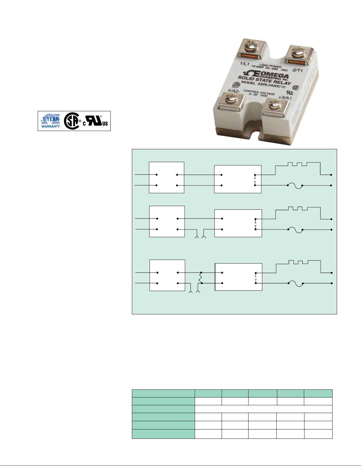
AC output SSR used with temperature controller with DC voltage SSR driver output
Temperature
Controller
Vac
AC output SSR used with temperature controller with mechanical relay output
Temperature
Controller
Vac
AC output SSR used with temperature controller with triac output
Temperature
Controller
Vac
Control
Side
0 or 5 Vdc,
Typically
Control
Side
Vac
Driving
SSR
Control Side
Load
Resistor
Vac
Driving
SSR
4
3
4
3
4
3
DC Input
SSR
AC Input
SSR
AC Input
SSR
Load
Side
1
2
Load
Side
1
2
Load
Side
1
2
Heater
Fast Blow
Fuse
Heater
Fast Blow
Fuse
Heater
Fast Blow
Fuse
Vac
Vac
Vac
Typical Applications
Common Specifications
Operating Temperature: -20 to 80°C
(-5 to 175°F)
Storage Temperature: -40 to 80°C
Capacitance: 8 pF, input to output (max)
Line Frequency Range: 47 to 63 Hz
Turn-On Time: 20 ms, AC; 05 cycle, DC
Turn-Off Time: 30 ms, AC; 05 cycle, DC
(-40 to 175°F)
Isolation: 4000 Vrms, input to output;
2500 Vrms input/output to ground
Output Specifications for Vac and Vdc Input Models
Specifications 10 Amp 25 Amp 50 Amp 75 Amp 100 Amp
Max On-State Current 10 A 25 A 50 A 75 A 100 A
Min On-State Current 100 mA
Max 1-Cycle Surge 150 A 300 A 750 A 1000 A 1200 A
Max 1 sec Surge 30 A 75 A 150 A 225 A 300 A
12T (60 Hz), A2sec 416 937 2458 5000 6000
P-111
Page 2
These SSR’s are of the twin SCR type, inherently
50.8 (2.000) 4.241
(0.167)
5.08
(0.200)
1.5748
(0.062)
112.17
(4.416)
6.35
(0.250)
C
47.625
(1.875)
A
B
120.65
(4.750)
3.175
(0.125)
R
8-32 TH'D
2 Places
50.8
(2.000)
more reliable and capable of higher overloads before
failure than triacs. Heat is developed in a solid state
relay due to the nominal voltage drop across the
switching device. To dissipate the heat, an SSR must
be mounted on a finned heat sink or aluminum plate.
An SSR should be located where the ambient temperature
is relatively low, since the current switching rating is
lowered as the temperature increases. Another SSR
characteristic is a small leakage current across the
output when the relay is open. Because of this, a
voltage will always exist on the load side of the device
In comparing SSR’s with mechanical contactors, the
SSR has a cycle life many times that of a comparably
priced contactor. However, SSR’s are more prone
to failure due to overload and improper initial wiring.
Solid state relays can fail, contact closed, on overload
circuits. It is essential that a properly rated, fast
blowing I
2
T fuse be installed to protect the load circuit
Finned heat sinks are anodized fabrications that come
complete with tapped mounting holes and screws.
See thermal rating curves and ordering instructions for
proper selection.
All SSRL series relays come with a thermally conductive
pad mounted on the baseplate. This will significantly
improve the thermal conductivity between the heat sink
and SSR baseplate. It is also suggested that 10"/lb of
torque be used on the SSR mounting screws.
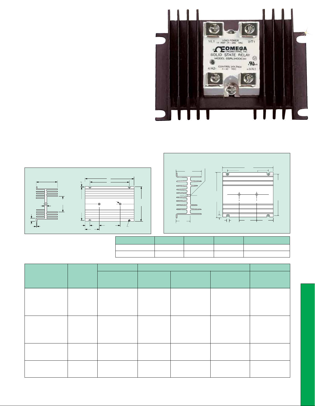
FHS-1 and FHS-2 Heat Sink
Dimensions:
mm (inch)
SSRL240DC50 solid state relay shown smaller than actual size with
FHS-2 heat sink. See P-114 for more information.
FHS Heat Sink Dimensions
and Specifications
FHS-6 Heat Sink
SSR MOUNTING HOLES (2) 8-32 THDS.
66.5
(2.62)
C
L
120.7
(4.75)
Dimensions: mm (in)
139.7
(5.50)
114.3 (4.50)
C
L
12.7
(0.50)
115.8
(4.56)
CENTERS
(SCREWS)
#6
SSR240 Series
Electrical Specifications
Input-Control Signal Output
Control Control Control Max Peak
Signal Signal Signal Input Voltage*
Model No. Type Voltage Turn-On Turn-Off Current (60 s Max)
SSRL240AC10
SSRL240AC25 AC
SSRL240AC50 control 90 to 280 Vac 90 Vac 10 Vac 10 mA 800V
SSRL240AC75 signal
SSRL240AC100
SSRL240DC10
SSRL240DC25 DC
SSRL240DC50 control 3 to 32 Vdc 3 Vdc 1 Vdc 14 mA 800V
SSRL240DC75 signal
SSRL240DC100
SSRL660AC50 AC
SSRL660AC75 control 90 to 280 Vac 90 Vac 10 Vac 10 mA 1200V
SSRL660AC100 signal
SSRL660DC50 DC
SSRL660DC75 control 4 to 32 Vdc 4 Vdc 1 Vdc 14 mA 1200V
SSRL660DC100 signal
Transients above table value should be suppressed.
*
36.6
(1.44)
END VIEW
Model No. A B C Thermal Rating
5.6
(0.22)
(TYP.)
5.1
(0.20)
(TYP.)
47.5
(1.87)
TOP VIEW
FHS-1 3.00" 2.50" 0.56" 2°C/W
FHS-2 5.50" 5.00" 1.81" 1.2°C/W
P-112
46.0
(1.81)
P
Page 3

10.0
57
(2.250)
43
(1.700)
47
(1.850)
11
(0.480) SQ.
28
(1.100)
12
(0.470)
45
(1.750)
OUTPUT
8.0
6.0
4.0
2.0
LOAD CURENT (AMPERES)
0.0
20 30 40 50 60 70 80
SSR-10 AMP
3.0°C/W
AMBIENT TEMPERATURE (°C)
25.0
20.0
15.0
10.0
5.0
LOAD CURENT (AMPERES)
0.0
SSR-25 AMP
2.0°C/W
3.0°C/W
20 30 40 50 60 70 80
AMBIENT TEMPERATURE (°C)
1.5°C/W
1.0°C/W
50.0
40.0
30.0
20.0
10.0
LOAD CURENT (AMPERES)
0.0
SSR-50 AMP
1.0°C/W
1.5°C/W
2.0°C/W
20 30 40 50 60 70 80
AMBIENT TEMPERATURE (°C)
0.7°C/W
°C/W
0.5
75.0
60.0
45.0
30.0
15.0
LOAD CURENT (AMPERES)
0.0
7
(0.275)
INPUT
11
(0.450) SQ.
SSR-75 AMP
0.5
°
°
C/W
C/W
1.0
º
C/W
1.5
°
C/W
20 25 30 35 40 45 50 55 60 65 70 75 80
0.7
AMBIENT TEMPERATURE (°C)
57
(2.250)
43
(1.700)
47
(1.850)
12
(0.470)
(1.750)
28
(1.100)
11
(0.480) SQ.
45
OUTPUT
Dimensions:
mm (inch)
22
20
(0.870)
(0.785)
6
(0.250)
100.0
90.0
80.0
70.0
60.0
50.0
40.0
30.0
20.0
10.0
LOAD CURENT (AMPERES)
0.0
0510 15 20 25 30 35 40 45 50 55 60 65 70 75 80
1.0
°
C/W
0.7
°
0.5
C/W
AMBIENT TEMPERATURE (°C)
SSR-125 AMP
SSR-100 AMP
125.0
112.5
100.0
87.5
75.0
62.5
50.0
37.5
25.0
12.5
LOAD CURENT (AMPERES)
0.0
0510 15 20 25 30 35 40 45 50 55 60 65 70 75 80
1.0
°
C/W
0.7
°
C/W
0.5
°
C/W
0.4
AMBIENT TEMPERATURE (°C)
°
C/W
°
C/W
0.4
°
C/W
SSR240 Series Output-Vac Load Specifications
Nominal Nominal Maximum
AC Line Load Contact
Maximum Off-State Leakage
(25°C Maximum Ambient)
Model Number Voltage Current Voltage Drop 120 Vac 240 Vac 440 Vac
SSRL240AC10 10 A
SSRL240AC25 25 A
SSRL240AC50 24 to 280 Vac 50 A 1.6V 0.1 mA 0.1 mA N/A
SSRL240AC75 75 A
SSRL240AC100 100 A
SSRL240DC10 10 A
SSRL240DC25 25 A
SSRL240DC50 24 to 280 Vac 50 A 1.6V 0.1 mA 0.1 mA N/A
SSRL240DC75 75 A
SSRL240DC100 100 A
SSRL660AC50 50 A
SSRL660AC75 48 to 660 Vac 75 A 1.6V 0.25 mA 0.25 mA 0.25 mA
SSRL660AC100 100A
SSRL660DC50 50 A
SSRL660DC75 48 to 660 Vac 75 A 1.6V 0.25 mA 0.25 mA 0.25 mA
SSRL660DC100 100 A
P-113
Page 4

FB-1, FB-2,
and FB-3 fuse blocks
shown with KAX-25 fuses.
Fuses
To Order
Model No. Capacity Dimensions (Dia. x L)
KAX-10 10 A 14 x 51 mm (0.6 x 2")
KAX-25 25 A 14 x 51 mm (0.6 x 2")
KAX-30 30 A 14 x 51 mm (0.6 x 2")
KAX-50 50 A 21 x 81 mm (0.8 x 3.2")
KAX-70 70 A 31 x 92 mm (1.2 x 3.6")
KBH-50 50 A 18 x 81 mm (0.7 x 3.2")
KBH-70 70 A 19 x 92 mm (0.7 x 3.6")
Fuse Blocks
To Order
Model No. of
No. Fuses Compatible Fuses
FB-1 1 KAX-10, KAX-25, KAX-30
FB-2 2 KAX-10, KAX-25, KAX-30
FB-3 3 KAX-10, KAX-25, KAX-30
BS-101 1 KAX-50, KAX-70, KAX-100,
Shunt Resistors
for Controllers with AC SSR (Triac) Output
To Order
Model No.* Value
Visit omega.com/ssrl240_660 for Pricing
and Details
Visit omega.com/ssrl240_660 for Pricing
and Details
KBH (all models)
Visit omega.com/ssrl240_660 for Pricing
and Details
SSRR20-12 2000 Ω, 12 watts
SSRR20-50 2000 Ω, 50 watts
SSRR15-12 1500 Ω, 12 watts
SSRR15-50 1500 Ω, 50 watts
12 W versions for 120 V circuits; 50 W for 240 V.
*
All models shown smaller
than actual size.
BS-101 fuse blockshown
with KAX-50 fuse.
How to Order:
1) Select solid state relay based on type of control
signal (AC or DC) and current switching
requirements for resistive load.
2) Select fast blow (I2T) fuse and fuse block.
It is essential that a fuse be installed to protect
the load circuit.
3) Select required finned heat sink based on max
ambient temperature and thermal rating curve
on previous page.
To Order
Nominal
Model No. Description Rating
SSRL240AC10 10 A
SSRL240AC25 AC control 25 A
SSRL240AC50 signal 50 A
SSRL240AC75 (280 Vac line) 75 A
SSRL240AC100 100 A
SSRL240DC10 10 A
SSRL240DC25 DC control 25 A
SSRL240DC50 signal 50 A
SSRL240DC75 (280 Vac line) 75 A
SSRL240DC100 100 A
SSRL660AC50 AC control 50 A
SSRL660AC75 signal 75 A
SSRL660AC100 (660 Vac line) 100 A
SSRL660DC50 DC control 50 A
SSRL660DC75 signal 75 A
SSRL660DC100 (660 Vac line) 100 A
FHS-1 2°C/W
FHS-2 Finned heat sink 1.2°C/W
FHS-6 0.7°C/W
Accessory
Model No. Description
SSRL-DINRAIL-ADAPT DIN rail adaptor for 10 A
Comes complete with operator’s manual.
Note: All SSRL Series come with thermally conducting pad.
Reference SSR330 Series for additional heat sinks.
Ordering Examples: SSRL240DC25, solid state relay, FHS-2,
finned heat sink, KAX-25, fuse, and FB-1, fuse block.
SSRL240AC10, solid state relay, FHS-1, finned heat sink,
KAX-10, fuse, and FB-1, fuse block.
Visit omega.com/ssrl240_660 for Pricing
and Details
models only
P
P-114
 Loading...