

Page 1
CirCuit Breakers
for BranCh CirCuit
ProteCtion
uL 489 aC & DC CirCuit Breakers
Miniature MCCB, CirCuit Breakers
UL Series
E301611
Pending
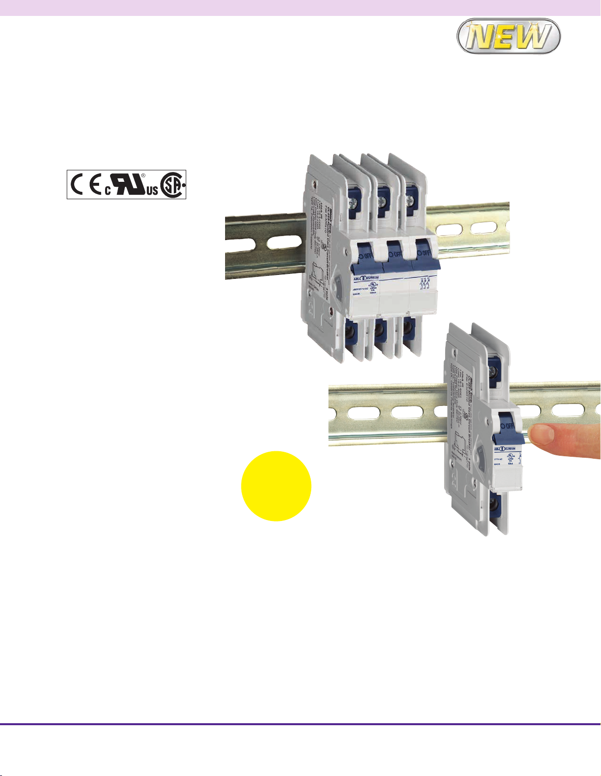
• DIN Rail Mounted
• Disconnect and Switching Function
• 17.5 mm (0.69") Width per Pole
• Thermal Magnetic and
Curent Limiting
• Available in AC and DC
• 240V, 480Y/277 Vac, 50/60Hz
• 125 Vdc (1-Pole), 250 Vdc (2-Pole)
• 10kA Short Circuit
Interrupting Capacity
• HACR Type 40°C (104°F)
• Line/Load Reversible
The UL 489 Series miniature molded case
circuit breakers are DIN rail mountable and
provide feeder and branch circuit protection
per UL 489. Circuit breakers can be reset and
reused over and over again, when compared
with a standard fuse that must be replaced
and discarded in compliance with special
disposal procedures. Typical uses include
convenience receptacles, motor controls,
load circuits leaving equipment, and heating
and air conditioning.
UL 489 Series miniature circuit breakers are
available in one-, two-, three- and four-pole
configurations and up to 23 different current
ratings from 0.3A to 63A and can safely be
used in applications up to 480Y/277 Vac
with a 10kA short circuit withstand rating.
Two levels of circuit protection available,
one for medium inrush startup currents to
provide protection for small transformers,
pilot devices, etc., and one with a magnetic
range to allow for higher inrush levels during
startup usually seen with motors. These
molded case circuit breakers are Din rail
mounted and, at only 17.5 mm wide, they are
extremely compact and reduce panel size.
DIN rail sold separately.
Visit omega.com/drtb-rail
For
Terminal
Blocks and
Enclosures. Visit
omega.com/auto
Accessories are field mounted on the UL
489 series circuit breakers for enhanced
control and monitoring capabilities. Field
mounting kits include all necessary parts
and instructions. Accessories can be gang
mounted on a single controller (the auxiliary
switch in the outside position). The mounting
arrangement links the internal latch-pins
for the tripping mechanisms, ensuring
simultaneous trips. Handles are linked to
simplify manual resetting. Accessories
include neutral pole, shunt and undervoltage
trip and auxiliary contacts.
AU-1C15UL, one pole
AC circuit breaker,
15 Amp C-trip curve.
AU-3C15UL, 3-pole
circuit breaker, 15 Amp
C-trip curve.
Applications
AC C-Trip Curve
Low inrush motors, resistive loads, wiring
protection, receptacles, lighting, and control
circuit applications. Relatively short thermal
trip delay and medium magnetic trip point.
AC D-Trip Curve
High inrush motors, transformers, power
supplies, heaters and reactive loads.
Relatively long thermal trip delay and very
high magnetic trip point.
DC C and D-Trip Curves
Telecommunication equipment, computer
equipment, uninterruptable power supplies.
1
Page 2
SPECIFICATIONS
Current/Voltage Rating:
AC: 0.3-63A – 240 Vac
AC: 0.3-32A 480Y/277 Vac
DC: 0.3-63A 125 Vdc 1-pole - 250 Vdc
2-pole
Electrical Life: 6000 cycles on/off
Mechanical Life: 10,000 cycles on/off
Calibration Temperature: 40°C (104°F)
Operating Temperature: -25 to 55°C
(-13 to 131°F)
Storage Temperature: -25° to 70°C
(-13° to 158°F)
Wire Connection: Copper wire only,
60/75°C
Short Circuit Interrupt Rating
NO. POLES TYPE 0.3-32 AMPS 40-63 AMPS
1
2-3
1
2
AC 10kA@120, 240, 277 V 10kA @120, 240V
AC 10kA@120, 240, 480Y/277 V 10kA @120, 240V
DC 10kA @ 125V 10kA @ 125V
DC 10kA @ 250V 10kA @ 250V
Short Circuit Interrupt Rating according to IEC 60947-2, DIN EN 60947-2
NO. POLES TYPE 0.3 - 32 AMPS 40-63 AMPS
1
2-3
Terminal Size Acceptability: Top 18-3
AWG, Bottom18-2 AWG
Tightening Torque Minimum/Maximum:
17.7/ 22lb-in. (2/2.2 Nm)
Terminal Protection Degree: IP20
AC 15kA @ 240V 15kA @ 240V
AC 15kA @ 415V 10kA @ 415V
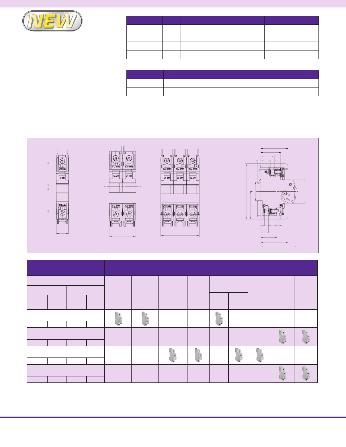
Dimensions:
Height: 105.3mm (4.15")
Width: One Pole 17.5mm (0.69"), 2 Pole
35mm (1.38"), 3 Pole 52.5 mm (2.07")
Depth: From Din rail 68.4 mm (2.69")
Dimensions: mm (in)
36.5 (1.43) 36.8 (144)
17.5 (.69)
1 Pole
35 (1.37)
2 Pole
52.5 (2.06)
3 Pole
Trip-Characteristics* Applications
Characteristic Trip Boundaries
Thermal Trip
Must not
Trip>100ms
Must Trip
<1hr
Magnetic Trip
Must not
Trip>100ms
Must Trip
at 100ms
Lighting
Wiring
Protection
Control
Circuits
Business
Equipment
Appliances
Transformers
Power
Supplies
Heaters
Inrush
Low
Motors
High
Inrush
105.3 (4.14)
52.5 (20.06)
14.5 (.57)
Reactive
51.5 (20.02)
37.5 (1.47)
25.5 (1.0)
67
34.5 (1.35)
8
(.314)
30.5 (1.2)
51.5 (2.02)
Telecommu-
Load
4
(.157)
68.4 (2.7)
nications/
Computer
Equipment
45 (1.77)
Power
Supplies
C-Characteristics AC
1.05xRC1.35xRC 5xRC 10xRC
C-Characteristics DC
1.05xRC1.35xRC 7xRC 14xRC
D-Characteristics AC
1.05xRC1.35xRC 10xRC 16xRC
D-Characteristics DC
1.05xRC1.35xRC 14xRC 22.4xRC
* The value of each characteristic is shown vertically beneath its corresponding heading.
Warning!
This information should only be used as a selection guide. The use of a Miniature Circuit Breaker in an application with a certain
Trip-Characteristic always requires prototype testing. It is the responsibility of the circuit design engineer to select the appropriate Miniature
Circuit Breaker for his specific application.
2
Page 3

C (AC) Trip Curve D (AC) Trip Curve
1.05-1.35xI
N
60
40
10
Minutes
Tripping time t
10
4x10
10
4x10
Seconds
10
Thermal Overload
4
“Must Trip” < 1 hr = 135% RC
“Must Not Trip” > 1 hr = 105% RC
1
10
4
1
0.4
-1
-2
-2
-3
-3
12345 6810 20 40 100
Multiple of Rated Current
0.3A Through 10A Rated Current
1.05-1.35xI
N
60
40
10
Thermal Overload
4
“Must Trip” < 1 hr = 135% RC
“Must Not Trip” > 1 hr = 105% RC
1
10
4
1
Tripping time t
0.4
-1
10
-2
4x10
-2
10
-3
4x10
Seconds Minutes
-3
10
123456 8 10 20 40 100
Multiple of Rated Current
0.3A Through 10A Rated Current
Accessories can be field mounted on
UL 489 Series miniature molded case
circuit breakers for enhanced control and
monitoring capabilities. Field mounting kits
include all necessary parts and instructions.
Accessories can be gang mounted on
a single controller (the Auxiliary Switch
in the outside position). The mounting
arrangement links the internal latch-pins
for the tripping mechanisms, ensuring
simultaneous trips. Handles are linked to
simplify manual resetting.
C (DC) Trip Curve D (DC) Trip Curve
1.05-1.35xI
N
60
40
10
Thermal Overload
4
“Must Trip” < 1 hr = 135% RC
“Must Not Trip” > 1 hr = 105% RC
1
10
4
1
Tripping time t
0.4
-1
10
-2
4x10
-2
10
-3
4x10
Seconds Minutes
-3
16
10
123456781014 20 40 100
Multiple of Rated Current
0.3A Through 10A Rated Current
Accessories
MODEL NUMBER DESCRIPTION
AU-N32UL
AU-N63UL
AU-H10UL
AU-H11UL
AU-H12UL
AU-FA12UL
AU-FA24UL
AU-FA48UL
AU-FA110UL
AU-UA120UL
Neutral pole for circuit breaker, 0.3 to 32a
Neutral pole for circuit breaker, 40 to 63A
1 Auxiliary contact, normally open
2 Auxiliary contact, 1 NO and 1 NC
3 Auxiliary contact, 1 NO and 2 NC
12 V AC/DC shunt trip, 1.3A
24 V AC/DC shunt trip, 0.6A
48 V AC/DC shunt trip, 0.2A
Shunt trip, 110 to 240 Vac/Vdc, 277 Vac, 0.25A @ 110V
0.5A @ 240V 0.58A @ 277V
Undervoltage Trip, 120 Vac, 60 Hz (UL Pending)
1.05-1.35xI
N
60
40
10
Thermal Overload
4
“Must Trip” < 1 hr = 135% RC
“Must Not Trip” > 1 hr = 105% RC
1
10
4
1
Tripping time t
0.4
-1
10
-2
4x10
-2
10
-3
4x10
Seconds Minutes
-3
10
123456 810 14 22.4 40 100
Multiple of Rated Current
0.3A Through 10A Rated Current
To Order Visit omega.com/ul489_Series for Pricing and Details
MODEL NUMBERS
ONE POLE AC TWO POLE AC THREE POLE AC ONE POLE DC TWO POLE DC RATED CURRENT
AU-1(*)03UL AU-3(*)03UL AU-3(*)03UL AU-1(*)03DL AU-3(*)03DL
AU-1(*)05UL AU-2(*)05UL AU-3(*)05UL AU-1(*)05DL AU-2(*)05DL
AU-1(*)1UL AU-2(*)1UL AU-3(*)1UL AU-1(*)1DL AU-2(*)1DL
AU-1(*)1.6UL AU-2(*)1.6UL AU-3(*)1.6UL AU-1(*)1.6DL AU-2(*)1.6DL
AU-1(*)2UL AU-2(*)2UL AU-3(*)2UL AU-1(*)2DL AU-2(*)2DL
AU-1(*)3UL AU-2(*)3UL AU-3(*)3UL AU-1(*)3DL AU-2(*)3DL
AU-1(*)4UL AU-2(*)4UL AU-3(*)4UL AU-1(*)4DL AU-2(*)4DL
AU-1(*)5UL AU-2(*)5UL AU-3(*)5UL AU-1(*)5DL AU-2(*)5DL
AU-1(*)6UL AU-2(*)6UL AU-3(*)6UL AU-1(*)6DL AU-2(*)6DL
AU-1(*)8UL AU-2(*)8UL AU-3(*)8UL AU-1(*)8DL AU-2(*)8DL
AU-1(*)10UL AU-2(*)10UL AU-3(*)10UL AU-1(*)10DL AU-2(*)10DL
AU-1(*)12UL AU-2(*)12UL AU-3(*)12UL AU-1(*)12DL AU-2(*)12DL
AU-1(*)13UL AU-2(*)13UL AU-3(*)13UL AU-1(*)13DL AU-2(*)13DL
AU-1(*)15UL AU-2(*)15UL AU-3(*)15UL AU-1(*)15DL AU-2(*)15DL
AU-1(*)16UL AU-2(*)16UL AU-3(*)16UL AU-1(*)16DL AU-2(*)16DL
AU-1(*)20UL AU-2(*)20UL AU-3(*)20UL AU-1(*)20DL AU-2(*)20DL
AU-1(*)25UL AU-2(*)25UL AU-3(*)25UL AU-1(*)25DL AU-2(*)25DL
AU-1(*)30UL AU-2(*)30UL AU-3(*)30UL AU-1(*)30DL AU-2(*)30DL
AU-1(*)32UL AU-2(*)32UL AU-3(*)32UL AU-1(*)32DL AU-2(*)32DL
AU-1(*)40UL AU-2(*)40UL AU-3(*)40UL AU-1(*)40DL AU-2(*)40DL
AU-1(*)50UL AU-2(*)50UL AU-3(*)50UL AU-1(*)50DL AU-2(*)50DL
AU-1(*)60UL AU-2(*)60UL AU-3(*)60UL AU-1(*)60DL AU-2(*)60DL
AU-1(*)63UL AU-2(*)63UL AU-3(*)63UL AU-1(*)63DL AU-2(*)63DL
Note: (*)= ”C” for C-curve and “D” for d-curve.
Ordering Example: AU-1C05UL 1-pole minature MCCB, AC circuit breaker rated for 0.5 A C-trip curve
AU-2D2UL 2-pole minature MCCB, AC circuit breaker rated for 2 A D-trip curve
0.3A
0.5A
1.0A
1.6A
2.0A
3.0A
4.0A
5.0A
6.0A
8.0A
10A
12A
13A
15A
16A
20A
25A
30A
32A
40A
50A
60A
63A
3
 Loading...