

Page 1
869O/OOZOUU
pmuey(l
s,Jow.mdo
Page 2
WARRANTY
j
OMEGA
warrants this unit
satisfac’tory
adds
warranty to cover handling and shipping time. This ensures that our customers receive
maximum coverage on each product. If the unit should malfunction, it must be returned
to the factory for evaluation. Our Customer Service Department will issue an Authorized
Return
OMEGA,
Howeve,r, this WARRANTY is VOID
with or
heat, moisture or vibration; improper specification; misapplication; misuse or other
operating conditions outside of OMEGA’s control. Components which wear or which are
damaged by misuse are not warranted. These include contact points, fuses, and
We are glad to offer
loa m
specified
OMEGA MAKES NO OTHER WARRANTIES OR REPRESENTATIONS OF ANY
KIND WHATSOEVER, EXPRESSED OR IMPLIED, EXCEPT THAT OF
ALL
ABIUTY
CLAIMED.
UMITATION
and tho total liability of OMEGA with
oontraot.
shall not exceed the
based. In no event shall OMEGA
sPecial
Every precaution for accuracy has been taken in the preparation of this manual, however,
OMEGA ENGINEERING, INC. neither assumes responsibility for any omissions or errors
that
products in accordance with the information contained in the manual.
service for a period of 13
arl
additional one (1) month grace period to the normal
(AR)
number immediately upon phone orwritten request. Upon examination by
if the unit is found to be defective it will be repaired or replaced
:shows
evidence of being damaged as a result of excessive corrosion; or current,
OlVlEGA
IMPUED
ma’1
only
free
and
WARRANTIES INCLUDING ANY WARRANTY OF MERCHANT-
AND FITNESS FOR A PARTICULAR PURPOSE ARE HEREBY DIS-
LIABIUTY:
OF
warranty,
damagea.
appear nor assumes liability for any damages that result from the use of the
to be free
suggertionr
warranta
defect..
of
nogligenoe,
purohmse
of defects in materials and workmanship and to give
month8
from date of purchase. OMEGA Warranty
if the unit shows evidence of having been tampered
be
use
parta
of
liable
buyer
on the
that the
remediea
The
indamnifioation,
price of the oomponsnt upon which liability is
i’,,
varioum
of our
manufaotured
sat
forth herein are exclusive
thio
&riot
oonmequehtiml,
for
,’
one
productm.
or&r, whether based onrespwt to
liability or
,;:
:
(1)
by it will be
:’
year
product
at no
charge.
triacs.
Neverthe-
TITLE
otherwise,
incidental or
:.
aa
AND
’
r
‘,
*_:_
. .
.>,’
/
RETURN REQUESTS
Direct all warranty and repair requests/inquiries to the OMEGA ENGINEERING Customer
Service Department.
203-359-7811;
FAX:
BEFORE RETURNING ANY
muURN
ORDER TO AVOID PROCESSING DELAYS). The assigned AR number should then be
marked on the outside of the return package and on any correspondence. Please have
the following information available BEFORE contacting OMEGA:
OMEGA’!; policy ic to make running
possible. That way our customers get the latest In technology end engineering.
OMEGA
16
0
Copyright 1993 OMEGA ENGINEERING, INC. All rights reserved
in this manualmavbe
without written permission from OMEGA ENGINEERING, INC.
IAR)
1. P.O. number under which theproduct was PURCHASED,
2. Model and serial number of the product, and
3. Repair instructions and/or specific problems you are having with the
product.
a registered trademark of OMEGA ENGINEERING, INC.
Call toll free in the USA and Canada:
International:
PRODUCT(S)
NUMBER
reproduoxf in
FROM OUR CUSTOMER SERVICE DEPARTMENT (IN
changes,
anvmanner,eitherwhollyorlnpartforanypurposowhatsoever
203-368-1660,
TO OMEGA,
not model
INQUIRIES
FAX:
-MUST
ohangeo,
whenever an Improvement is
lncludlng Illustrations. Nothing
1-800-622-2378,
OBTS
203-369-7807.
Printed in U.S.A.
Page 3

SOLID STATE SWITCHES
INTERCHANGEABLE MODULES
AC AND DC
INTRODUCTION
The OMEGA@ Solid State Switches are available with four types
of modules:
input module (Model
DC05-B);
The output modules switch low level signals
high level ac or dc circuits; the input modules switch high level ac or dc
signals to low level signals for communication to the computer.
I)
an ac output module
ACIS-B);
(Model
3)
a dc output module (Model
and 4) a dc input module (Model
FEATURES
??
4000 Volt isolation
?
Logic levels switch high level ac and dc circuits
?
High level ac and dc signals switch logic circuits
BACKPLANES
OMEGA offers a complete series of versatile backplanes to mount 4, 8,
16, or 24 Solid State Switches. The backplanes include LED indicators to
indicate signal status, pull-up resistors to avoid undefined states, and
power fuses for overload protection on each channel.
SSS-PC4-B:
Logic power and ground are common on the signal side.
Four channel backplane with screw terminal connections.
AC05-B);
DC15-B).
(TTLI
from the computer to
2)
an ac
1
Page 4
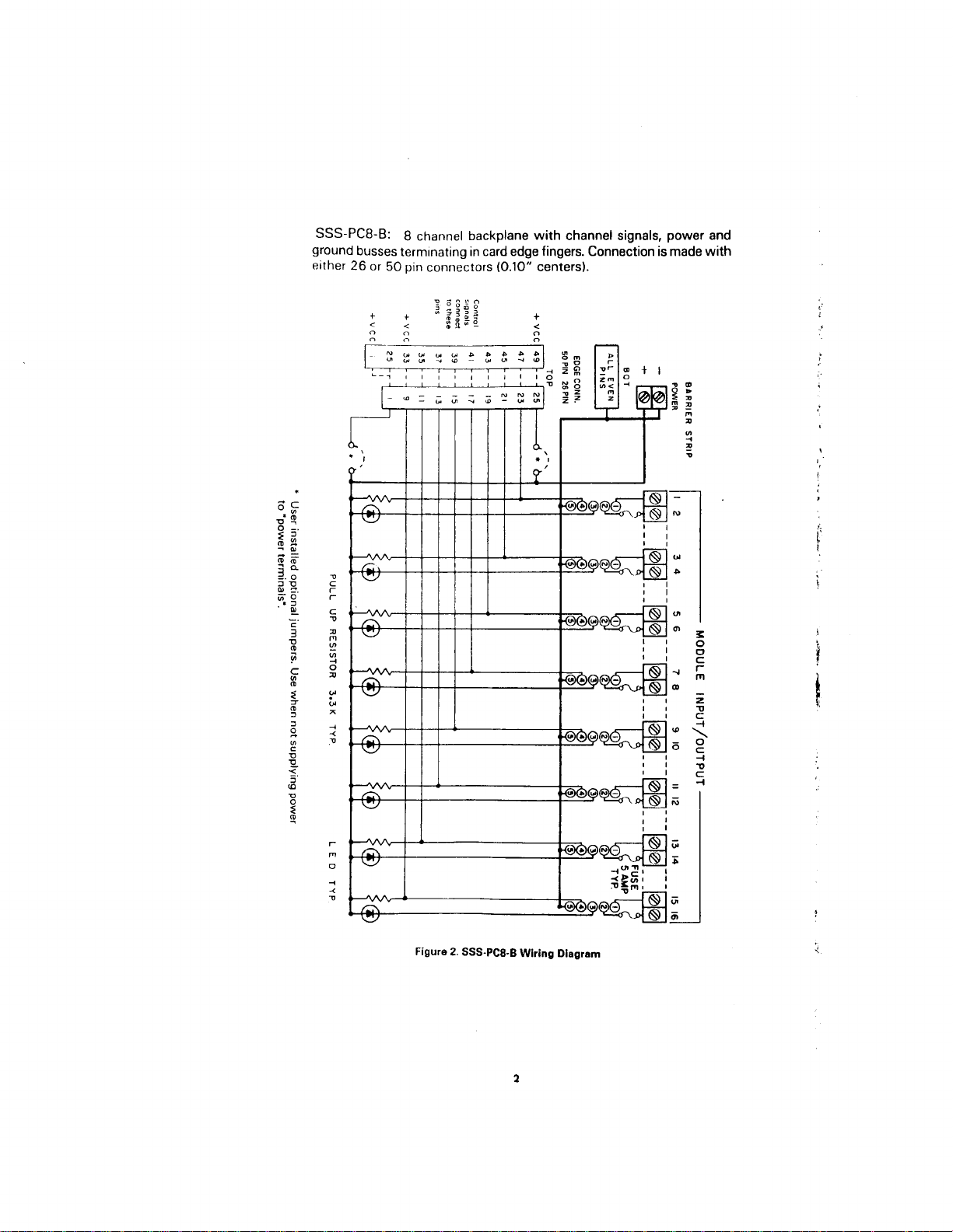
SSS-PC8-B:
ground busses
8 channel backplane with channel signals, power and
terminating in card edge fingers. Connection is
either 26 or 50 pin connectors (0.10” centers).
+
made with
Figure 2.
SSS-PCB-B
Wiring
2
Diagrem
Page 5

SSS-PCIG-I
excepl
that
3; The 16 channel backplane is similar to the SSS-PCSB,
it is available with
only 50 pin card edge connectors.
Figure 3.
SSS-PClG-B
3
Wiring Diagram
Page 6

SSS-PC24-B:
and the
nections. All
The 24 channel blackplane is similiar to
SSS-PCIG-8. The
SSS-PC24-El
edge connections are gold plated
maximum corrosion resistance.
SSS-PCS6
the
can be used for signal con-
over nickel plating
for
SSS-PC41-B:
isolated
from each other. Without the common
Same as
SSS-PC4-B
output modules may be used.
Figure
SSS-PC41-9:
4.
Control Circuit
Module Input from
ACCESSORIES
except that all
signal ground,
channels are
only
Connect your control
voltage(25V
lo the
module
‘+’
and
inputs.
to
5Vmax)
“-’
of the
i
*
PART NUMBER
OMX-1804
SSSICA2
SSS-CA6
SSS-CA10
SSS-Fl
SSSF5
DESCRIPTION
Solder eye type 50 pin connector
2 ft ribbon cable with 50 pin connector
6 ft ribbon cable assembly
10 ft ribbon cable assembly
1
amp optional logic power
fuse
5 amp spare channel power
4
Page 7

AC OUTPUT MODULE-
AC05-B
+
wcl,e
Figure 5. Wiring Diagram for the
SPECIFICATIONS-
LINE VOLTAGE:
CURRENT RATING:
ONE CYCLE SURGE:
SIGNAL INPUT RESISTANCE:
SIGNAL PICKUP VOLTS DC:
SIGNAL DROPOUT VOLTS DC:
PEAK REPETITIVE VOLTAGE:
MAXIMUM CONTACT DROP:
OFF STATE LEAKAGE:
MINIMUM LOAD CURRENT:
ISOILATION INPUT TO OUTPUT:
CAPACITANCE INPUT TO OUTPUT:
DVIDT:
STATIC
COMMUTATING
OPERATING TEMPERATURE:
STORAGE TEMPERATURE:
1x05-B
DVIDT:
AlSOCOmpallble
3-sla1eouIpu1
Poleor
TOlml
w,,n
AC05-B
24 to 240
Vat
3 amps (operating ambient
+7OOC.
2
to
amps at
80 amps peak
250 R
2.5
V, 8 V max.
1v
600 V
1.6 V
6mA RMS
20
mA
4000 V RMS
8
Pf
200 V/microsecond
0.5 power factor loads
snubber)
+8O”C
-30” to
-40” to
+lOO”C
min.
r
-30’
70°C
I
i
Ibuilt-in
;
4
Page 8

AC INPUT MODULE
-ACI&B
Figure
SPECIFICATIONS
AC INPUT LINE VOLTAGE:
INPUT CURRENT AT MAX. LINE:
ISOLATION INPUT TO OUTPUT:
INPUT ALLOWED
TURN ON TIME:
TURN OFF TIME:
OUTPUT TRANSISTOR:
OUTPUT CURRENT:
OUTPUT LEAKAGE 30 V DC
NO INPUT:
OUTPUT VOLTAGE DROP:
LOGIC SUPPLY VOLTAGE DC:
LOGIC SUPPLY CURRENT:
OPERATING
STORAGE TEMPERATURE:
AMBIENT
6. Wiring Diagram for the
-ACl5-6
NO OUTPUT:
FOR
,.
AC15
90 to 140 V ac
mA
10
4000 V
RMS
40V(rms)
20 ms max.
30 ms max.
30 V breakdown
50
mA
gA
max.
100
mA
to
mA load
+70°c
+looOc
0.4 V at 50
4.5 to 6 V
16
-300
-40” to
1
I
6
Page 9

DC OUTPUT
MODULE-DC05-B
Figure 7. Wiring Diagrem for the
DCOS-B
-
SPEClF:lCATlONS
LOAD VOLTAGE RATING:
OUTPUT CURRENT RATING:
OFF STATE LEAKAGE:
ISOLATION INPUT TO OUTPUT:
SIGNAL PICKUP VOLTAGE:
SIGNAL DROPOUT VOLTAGE:
SIGNAL INPUT RESISTANCE:
ONE SECOND SURGE:
TURN ON TIME:
TURN OFF TIME:
MAXIMUM CONTACT DROP:
OI’ERATING TEMPERATURE:
STORAGE TEMPERATURE:
DCOI-B
60Vd c
3 amps (operating ambient
+70°C.
to
amps at
mA max.
1
3 amps at
70°C)
45OC, 2
4000 V RMS
2.5 V; 8 V max.
1v
n
220
5 amps
ps
100
0.75 ms
1.6 V
-30” to
+70” c
+loo”
-40” to
c
-
30’
Page 10

DC INPUT MODULE--C&- B
MO”NT,NG RACK
PLUG
IN
MOD”LE
Figure 8. Wiring Diagram for the
DCI5-B
-
SPECIFICATIONS
INPUT LINE VOLTAGE:
INPUT CURRENT:
ISOLATION INPUT TO OUTPUT:
CAPACITANCE INPUT TO OUTPUT:
INPUT ALLOWED FOR NO OUTPUT:
TURN ON TIME:
TURN OFF TIME:
OUTPUT TRANSISTOR:
OUTPUT CURRENT:
OUTPUT LEAKAGE 30 V dc
NO INPUT:
OUTPUT VOLTAGE DROP:
LOGIC SUPPLY VOLTAGE:
LOGIC SUPPLY CURRENT:
OPERATING AMBIENT:
DCl5.B
lOto32Vdc
32mAat32V
4000 V RMS
8 Pf
2mAor3V
5 ms max.
5 ms max.
30 V breakdown
mA
50
PA
max.
100
0.4 V at 50
4.5to6V;
mA
12to
12mA; 15mA
+70°c-300
to
18V
c
Page 11

FAX:
Servicing
USA
and Canada: Call
OMEGA
OMEGA Engineering, Inc.
One Omega
Stamford, CT 06907-0047 U.S.A.
Headquarters:
Sales: l-800-826-6342
Customer
Engineering
(203)
359-7700 TELEX: 996404 EASYLINK: 62968934
Service: l-800-622-2378
:
l-800-872-9436/
Drive, Box 4047
359-1660
(203)
l-BOO-TC-OMEGA
/
I-800-622-BEST
/
I-800-USA-WHEN
Toll
Free
CABLE: OMEGA
Servicing Europe: United Kingdom
OMEGA Technologies Ltd.
1,
P.O. Box
Telephone: (0455) 285520 FAX:
The OMEGA Complete Measurement and
Control Handbooks
r/
Temperature
r/
Pressure, Strain
fl
Flow and Level
Broughton
6XR, England
LE9
&
Force
,_
Sales and Distribution Center
Astley, Leicestershire
(0455) 283912
&
Encyclopedias”
pH
and Conductivity
c/
r/
Data Acquisition Systems
c/
Electric Heaters
Call
fior
Your
FREE
Handbook Set Today:
(203)
359-RUSH
Page 12

OMEGA@ . . .
Your Source for
Process Measure ment and Control
TEMPERATURE
w
Thermocouple,
w
Panels
m
W ire: Thermocouple, RTD &Thermistor
w
Calibrators
m
Recorders, Controllers
[ET
Infrared Pyrometers
&
PRESSURE
[ET
Transducers
[IZT
Load Cells
w
Displacement Transducers
w
Instrumentation &Accessories
/
FLOW
m
[gr
w
W
pH
@’
[EY
m
w
LEVEL
IRotameters,
Air Velocity Indicators
Turbine/Paddlewheel
Totalizers
/
CONDUCTIVITY
pH
Electrodes, Testers
E3enchtop/Laboratory
Controllers, Calibrators, Simulators
Industrial
RTD &Thermistor Probes, Connectors,
Assemblies
& Ice Point References
&
Process Monitors
/
/
STRAIN
& Strain Gauges
& Pressure Gauges
Gas Mass Flowmeters
Batch Controllers
&
pH
& Conductivity Equipment
FORCE
Systems
& Accessories
Meters
&
Flow Computers
&
Pumps
DATA ACQUISITION
m
Data Acquisition and Engineering Software
w
Communications-Based Acquisition Systems
&
m
Plug-in Cards for Apple, IBM
[ET
Datalogging Systems
w
Recorders, Printers
HEATERS
w
Heating Cable
m
Cartridge
w
lrnmersion
&+ ’
Flexible Heaters
(a*
Laboratory Heaters
& Strip Heaters
&
Band Heaters
&
Plotters
Compatibles
 Loading...