

Page 1
CONTROLS
Re-Order from
omegamation.com
Omegamation
TM
1-888-55-OMEGA
1-888-55-66342
1-888-55-66342
Instruction Manual
For DC Input Variable Speed Controls
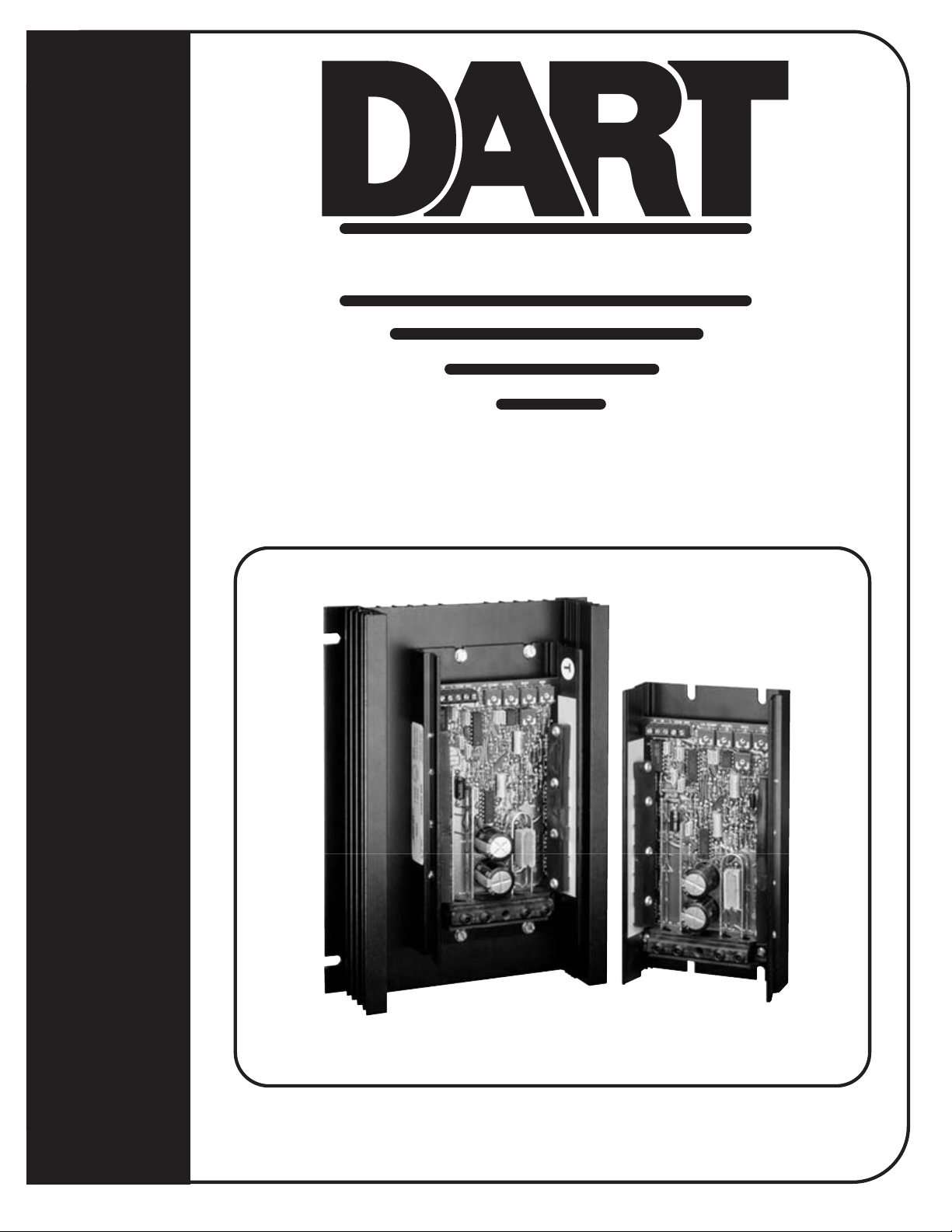
65E CONTROL SERIES
P.0. Box 10
5000 W. 106th Street
Zionsville, Indiana 46077
Phone (317) 873-5211
Fax (317) 873-1105
www.dartcontrols.com
A-5-3276DLT65E (0910)
Page 2

TABLE OF CONTENTS
WARRANTY ............................................................................................................................................................................... 1
STANDARD FEATURES ........................................................................................................................................................... 1
CONTROL DIMENSIONS .......................................................................................................................................................... 1
MOUNTING DIMENSIONS......................................................................................................................................................... 2
INSTALLATION.......................................................................................................................................................................... 2
HOOK-UP DIAGRAMS ........................................................................................................................................................... 2-3
INHIBITING THE CONTROL.......................................................................................................................................................3
TRIMPOT ADJUSTMENTS ..................................................................................................................................................... 3-4
IN CASE OF DIFFICULTY ......................................................................................................................................................... 4
MODEL SELECTION ................................................................................................................................................................. 4
SPECIFICATIONS ...................................................................................................................................................................... 4
65E SERIES PARTS PLACEMENT & LIST .............................................................................................................................. 5
65E SERIES SCHEMATIC ......................................................................................................................................................... 6
REPAIR PROCEDURE & PRODUCT LINE ......................................................................................................... BACK COVER
WARRANTY
Dart Controls, Inc. (DCI) warrants its products to be free from defects in material and workmanship. The exclusive remedy for this
warranty is DCI factory replacement of any part or parts of such product which shall within 12 months after delivery to the purchaser
be returned to DCI factory with all transportation charges prepaid and which DCI determines to its satisfaction to be defective. This
warranty shall not extend to defects in assembly by other than DCI or to any article which has been repaired or altered by other
than DCI or to any article which DCI determines has been subjected to improper use. DCI assumes no responsibility for the design
characteristics of any unit or its operation in any circuit or assembly. This warranty is in lieu of all other warranties, express or implied;
all other liabilities or obligations on the part of DCI, including consequential damages, are hereby expressly excluded.
NOTE: Carefully check the control for shipping damage. Report any damage to the carrier immediately. Do not attempt to operate
the drive if visible damage is evident to either the circuit or to the electronic components.
All information contained in this manual is intended to be correct, however information and data in this manual are subject to change
without notice. DCI makes no warranty of any kind with regard to this information or data. Further, DCI is not responsible for any
omissions or errors or consequential damage caused by the user of the product. DCI reserves the right to make manufacturing
changes which may not be included in this manual.
WARNING
Improper installation or operation of this control may cause injury to personnel or control failure. The control must be
installed in accordance with local, state, and national safety codes. Make certain that the power supply is disconnected
before attempting to service or remove any components!!! If the power disconnect point is out of sight, lock it in
disconnected position and tag to prevent unexpected application of power. Only a qualified electrician or service
personnel should perform any electrical troubleshooting or maintenance. At no time should circuit continuity be checked
by shorting terminals with a screwdriver or other metal device.
STANDARD FEATURES
l
Provides smooth variable speed capability for mobile equipment
l
Maintains variable speed control as batteries discharge
l
Adjustable maximum speed, minimum speed, current limit, I.R. compensation, and accel
l
Inhibit terminal permits optional start-stop without breaking battery lines
l
Speed potentiometer, knob, and dialplate included
l
Increases range or running time of battery operated equipment through high efficiency
l
65E40 and 65E60 series only - Automatic current limit foldback decreases current limit to 50% of setpoint when
heatsink temperatures reach 80
o
C. - provides protection from overheating
CONTROL DIMENSIONS
MODEL WIDTH LENGTH DEPTH WEIGHT
inches (centimeters) oz. (gms.)
65E20 3.7 (9.40) 7.0 (17.8) 1.70 (4.32) 10.5 (297)
65E40 3.7 (9.40) 7.0 (17.8) 1.70 (4.32) 13.4 (379)
65E60 6.7 (17.1) 9.0 (22.9) 2.27 (5.77) 34.0 (962)
1
Page 3

MOUNTING DIMENSIONS
1.70”
SIDE VIEW
2.27”
2.00”
3.62”
65E20 & 65E40 MOUNTING
.188 DIA.
1.75”
(4 SLOTS)
65E60 MOUNTING
7/32” DIA.
(4 SLOTS)
7.00”
6.50”
TOP VIEW
9.00”
7.50”
.344”
SLOT DEPTH
.75”
SIDE VIEW
SIDE VIEW
6.30”
6.70”
When mounting the control, allow clearance above
TOP VIEW
NOTE:
components to prevent shorting
TOP VIEW
Caution: Do not mount controller where ambient temperature is outside the range of -10° C (15° F) to 45° (115° F).
INSTALLATION
Before attempting to wire the control, make sure all power is disconnected. Recheck code designation to assure proper voltage
is present for the control. Caution should be used in selecting proper size of hook-up wire for current and voltage drop. Note: the
battery and armature wire size on 65E models must be a minimum of 12 gauge.
HOOK-UP DIAGRAMS
WARNING:
DO NOT REVERSE POSITIVE AND NEGATIVE BATTERY LEADS. THIS WILL DAMAGE THE CONTROL.
TO CHANGE MOTOR DIRECTION, INTERCHANGE THE POSITIVE AND NEGATIVE ARMATURE LEADS.
Refer to the wiring diagrams below for proper connection of DC Voltage, Armature, and Speedpot wiring to the control.
CAUTION !! TURN POWER OFF WHILE MAKING CONNECTIONS .
To properly adjust the CURRENT LIMIT setting, a DC ammeter should be placed in series with the armature line. This meter can
be removed after the control is adjusted.
2
(continued)
Page 4

++
++
(continued)
-
Motor
Motor and battery wire must
be a minimum of 12 ga. and
-
+
+
Customer supplied
SPST switch
Caution:
a maximum of 6 ga.
Battery
65E SERIES HOOK-UP DIAGRAM
Pot High (P2-1)
-Battery (P1-1)
-Arm (P1-2)
No Connect (P1-3)
+Battery (P1-4)
+Arm (P1-5)
P1
Pot Wiper (P2-2)
Pot Low (P2-3)
Common (P2-4)
Inhibit (P2-5)
Current Limit
65E REVERSING HOOK-UP DIAGRAM
P2
Orange
I.R. Comp.
Accel
Max Speed
Min Speed
White
Red
5Ký
Speedpot
Optional
Inhibit
(see hook-up
below)
Customer supplied
3PDT Center-off
Center-blocked switch
Motor
-
Battery
Customer
supplied
SPST switch
Caution:
Motor and battery wire must
be a minimum of 12 ga. and
a maximum of 6 ga.
+
Relays may be used in place of switch, but a neutral position must be provided
to prevent plug reversing. Do not engage opposite direction until motor has
come to a complete stop. Failure to do so may result in damage to the control.
-Battery (P1-1)
-Arm (P1-2)
No Connect (P1-3)
+Battery (P1-4)
+Arm (P1-5)
P1
INHIBITING THE CONTROL
Using inhibit input - provide fast start-
stop by bypassing accel/decel circuit
White
5Ký
Speedpot
Optional
Inhibit
(see hook-up
below)
Pot High (P2-1)
Pot Wiper (P2-2)
Pot Low (P2-3)
Common (P2-4)
Inhibit (P2-5)
Current Limit
P2
Red
Orange
I.R. Comp.
Accel
Max Speed
Min Speed
Inhibit via speedpot - provides starting and
stopping through accel/decel parameters
Pot High (P2-1)
Pot Wiper (P2-2)
Pot Low (P2-3)
Common (P2-4)
Inhibit (P2-5)
P2
SPST Switch
open = run
close = stop
Pot High (P2-1)
Pot Wiper (P2-2)
Pot Low (P2-3)
Common (P2-4)
Inhibit (P2-5)
P2
White
Red
Orange
SPST Switch
open = stop
close = run
5KW
Speedpot
Note: Always use a shielded cable when connecting to the inhibit terminal. The shield of the cable should connect to the Common
terminal of the control.
TRIMPOT ADJUSTMENTS
Before the power is applied, the speed potentiometer and trimpots should be preset as follows:
TRIMPOT PRESET
1. Preset speedpot fully CCW, preset Max trimpot CW 1/2 way, preset Current Limit trimpot fully CW, preset Min trimpot fully
CCW, preset Accel trimpot CW 1/2 way, preset I.R. trimpot fully CW.
DC power can now be applied to the system and the control adjusted as directed below:
TRIMPOT ADJUSTMENT
2. Increase the MIN trimpot in a clockwise direction until the desired minimum speed is reached.
3. Turn the Speedpot fully clockwise and adjust the MAX trimpot until the desired maximum speed is reached.
3
(continued on following page)
Page 5

(continued)
4. Adjust the ACCEL trimpot to achieve the desired soft start time. CW rotation will increase accel time.
5. Rotate the CURRENT LIMIT trimpot fully CCW until the motor begins to stall. Apply a full load to the motor. While motor
is stalled adjust the CURRENT LIMIT trimpot CW until a desired current setting is obtained.
6. Adjust I.R. trimpot CW 1/2 way. If motor RPM is inconsistent (jumpy), rotate I.R. trimpot CCW until rotation is stable.
IN CASE OF DIFFICULTY
If a newly installed control will not operate, it is likely that a terminal or connection is loose. Check to make sure connections are
secure and correct. If the control is still inoperative, refer to the following chart for reference:
PROBLEM POSSIBLE CAUSE(S) CORRECTIVE ACTION
Motor doesn’t run • Incorrect or no power Install proper service
• Speedpot set at zero Rotate speedpot fully CW
• Worn motor brushes Replace motor brushes
• Current limit set too low Adjust current limit trimpot CW
Motor “hunts” • Max trimpot set too high See “Trimpot Adjustments” - page 3-4
• I.R. Comp. trimpot set too high See “Trimpot Adjustments” - page 3-4
Motor runs at “full speed” • Loose speedpot connections Secure all connections
uncontrollable • Min. or Max. trimpots not properly adjusted See “Trimpot Adjustments” - page 3-4
• Possible control failure Send to Dart Controls, Inc.
Motor rotates in wrong direction • Motor armature hooked up backwards Reverse armature + and - leads
Motor stalls under a light load • Current limit trimpot improperly adjusted See “Trimpot Adjustments” - page 3-4
MODEL SELECTION
INPUT VOLTAGE OUTPUT VOLTAGE CONTINUOUS CURRENT MODEL NUMBER
12 VDC ± 15% 0 - 12 VDC 20 amps D.C. 65E20-12
12 VDC ± 15% 0 - 12 VDC 40 amps D.C. 65E40-12
12 VDC ± 15% 0 - 12 VDC 60 amps D.C. 65E60-12
24 VDC ± 15% 0 - 24 VDC 20 amps D.C. 65E20*
24 VDC ± 15% 0 - 24 VDC 40 amps D.C. 65E40*
24 VDC ± 15% 0 - 24 VDC 60 amps D.C. 65E60*
36 VDC ± 15% 0 - 36 VDC 20 amps D.C. 65E20*
36 VDC ± 15% 0 - 36 VDC 40 amps D.C. 65E40*
36 VDC ± 15% 0 - 36 VDC 60 amps D.C. 65E60*
* 24 volt and 36 volt units with the same current ratings are interchangeable (ie. 24 volt unit will operate with 36 volt input and
a 36 volt unit will operate with 24 volt input, same current rating).
SPECIFICATIONS
65E20 65E40 65E60
Load current (continuous) 20 amps 40 amps 60 amps
Speed adjustment 5K
Speed range 30 : 1
Overload capacity 200% for 10 seconds; 150% for one minute
Current limit adjustable100% to 200% of full motor load, up to continuous current rating (page 4)
Acceleration adjustable - 0 to 10 seconds
Deceleration non-adjustable - 0.5 seconds
Maximum speed adjustable - 50 to 100% of base speed
Minimum speed adjustable - 30% of max speed
Connections barrier terminal block (12Ga. to a maximum 6 Ga.)
Speed regulation 1% of base speed via adjustable I.R. Compensation trimpot
Operating temperature -10°C to +45°C (14°F to 113°F)
Package configuration black anodized aluminum extrusion
Internal operating frequency approximately 1.6K Hertz
Thermal protection N/A Current foldback at 80
ΩΩ
Ω potentiometer
ΩΩ
or
0 to +10VDC input signal
o
C. heatsink temperature
4
Page 6

65E40 / 65E60 PART PLACEMENT & LIST
RESISTORS
R1
300& 5W
R2
47K
R3
470&
R4
47K
R5
470&
R6
10K
R7
20K MAX
R8
33K
R9
220K
R10
47K
R11
10K
R12
100K
R13
10K
R14
180K
R15
250K ACCEL
R16
20K 1/4W 1%
R17
470K
R18
300K
R19
47K
R20
5K MIN
R21
82K
R22
10K
R23
4.7K
R24
6.8K
R25
10K
R26
4.7K
R27
47K
R28
10K
R29
300K
R30
20K CUR. LIM.
R31
4.7K
R32
5K I.R. COMP
R33
100K
R34
47K
R35
2.7K
R36
22&
R37
22&
R38
22&
R39
22&
R40
22&
R41
22&
R42
47K
R43
1.2M
R44
150&
R45
5K SPEEDPOT*
R46
22K
R47
680K
R48
2.7K
R49
100K
R50
100K
R51
15K
MISCELLANEOUS
PCB
P1 (-1 thru -5)
P2 (-1 thru -5)
RL1
RL2
RL3
SW1
A-4-2519B PRINTED CIRCUIT BOARD
5 POS. TERMINAL BLOCK
5 POS. BARRIER TERMINAL STRIP
RLB2508X RAIL
RLPRN910 RAIL
RLB25011XB RAIL
67F080 TEMP .SWITCH
CAPACITORS
C1
C2
C3
C4
C5
C6
C7
C8
C9
C10
C11
C12
C13
C14
C15
.1µF 63V
.1µF 63V
.22µF 100V
.1µF 63V
.1µF 63V
.22µF 100V
.1µF 63V
.01µF 100V
.01µF 100V
47µF 16V
1000µF 50V
1000µF 50V
.1µF 63V
.1µF 63V
.01µF 100V
DIODE
D1
D2
D3
D4
D5
D6
D7
1N4005
1N4005
1N5349B
1N963B
1N914B
1N5233B
1N914B
ACTIVE
DEVICES
Q1
Q2
Q3
Q4
Q5
Q6
Q7
Q8
Q9
Q1
IRFZ44
IRFZ44
IRFZ44
IRFZ44
IRFZ44
IRFZ44
IRFZ44
IRFZ44
IRFZ44
IRFZ44
IC PACKAGES
U1
U2
U3
U4
40106 IC
LM324 IC
LM324 IC
LM358 IC
H W L COM INH
R27
P2-1 P2-2 P2-3 P2-4 P2-5
U1
Q6
Q5
Q4
Q3
C
R35
R19
R34
C4
R41
R40
C10
R39
R38
R33
C2
C9
C15
C5
R22
R21
+
C7
R10
R9
RL2RL1
R26
R32
D5
R49
R46
U2
R25
R24
R23
U3
C8
C13
R47
C6
C14
R14
R15
U4
R50
R48
D7
C3
R12
R44
R5
R3
R13
+
R37
Q2
Q1
R36
P1-1 P1-2 P1-4 P1-5
-B -A +B +A
C12
+
C11
R18
RL3
MINMAXACCELI.R. COMP
R7
R4
R1
R29
D1
R6
R11
D4
R28
R42
C.L
R17
D3
R30
R8
R43
R20
D6
R16
R31
R51
D2
R2
SW1
Q10
Q9
Q8
Q7
65E20-12
CHANGES:
C12
Q1
Q2
Q3
Q4
Q7
Q9
Q10
R1
R6
R28
R31
R35
R42
R48
DELETE
DELETE
DELETE
DELETE
DELETE
DELETE
DELETE
DELETE
10& 1W
22K
4.7K
2.2K
1K
22K
1K
65E20
CHANGES:
C12
DELETE
Q1
DELETE
Q2
DELETE
Q3
DELETE
Q4
DELETE
Q7
DELETE
Q9
DELETE
Q10
DELETE
R48
1K
65E40/60-12
CHANGES:
R1
10& 1W
R6
22K
R31
2.2K
R35
1K
R42
22K
R48
1K
5
* SPEEDPOT IS MOUNTED REMOTE
NOTE: ALL RESISTORS 1/8W UNLESS NOTED OTHERWISE
Page 7

D2
+12V
NOTES:
1N4005
U1 - 40106
U2 - LM324
U3 - LM324
U4 - LM358
R1
5W
300Ω
D3
1N5349B
16V
C10
47µF
+B
R2
P1-4
47K
12
MAX
D
65E SERIES SCHEMATIC
S
Q10
IRFZ44
10& 1W
22K
2.2K1K22K
R1R6R31
Q2
IRFZ44
10K
R35
R11
10K
R42
R37
1K
R48
SGD
22Ω
C7
.1µF
+12V
63V
S
D
Q9
IRFZ44
D
S
Q8
IRFZ44
D
S
Q7
IRFZ44
-A
+A
MOTOR
P1-5
50V
C12
1000uF
50V
C11
1000uF
R4
47K
R3
470Ω
13
+
-
R6
U3-4
14
R7
20K
10K
D4
1N963B
cw
R44
150&
+12V
Q1
P1-2
R5
470Ω
R8
C6
100V
.22µF
R15
250K
ACCEL
CW
1%
R17
20K
R16
470K
1/2W
65E40/60-12
D
IRFZ44
R36
22Ω
C8
.01µF
1
+12V
U3-1
+
3
47K
R10
33K
R9
7
U3-2
-
+
5
6
R12
100K
R14
8
U3-3
-
9
CHANGES:
SGD
100V
11
-
2
220K
R13
180K
+
10
65E20-12
CHANGES:
Q3
IRFZ44
R38
+12V
R43
1.2M
R23
4.7K
DELETE
DELETE
DELETE
DELETE
DELETE
C12Q1Q2Q3Q4Q7Q9
SGD
Q4
IRFZ44
22Ω
2
14
U1-1
1
C9
100V
.01µF
8
+12V
U2-3
+
1
+12V
10K
R25
DELETE
DELETE
R39
10K
R22
+12V
11
-
9
DELETE
10& 1W
Q10R1R6
SGD
22Ω
4
U1-2
3
R47
680K
R26
4.7K
R42
22K
5
Q5
+
R24
47K
4.7K
2.2K1K22K
R28
R31
IRFZ44
8
9
7
U2-2
6.8K
U1-4
-
R35
6
5
R42
U1-3
6
C4
R40
1K
R48
.1µF
R46
63V
SGD
22Ω
D7
22K
65E20
CHANGES:
Q6
IRFZ44
10
U1-5
11
- ARM
15K
R51
1N914B
6
-
U4-2
7
D5
1N914B
D1
1N4005
DELETE
DELETE
DELETE
DELETE
C12Q1Q2Q3Q4Q7Q9
S
G
R41
22Ω
12
7
U1-6
13
3
+
1
D6
1N5233B
5
R48
2.7K
+
C15
100V
.01µF
+12V
47K
R27
12
+
-
U2-4
14
DELETE
DELETE
DELETE
R
LINE
R34
2
-
U2-1
R33
SW1
TEMP SWITCH
8
R2
13
DELETE
1K
Q10
R48
47K
C1
100K
C3
.22µF
.1µF
C.L.
CW
100V
63V
R31
R29
P1-1
4.7K
R30
-B
ALL RESISTORS 1/8W UNLESS NOTED OTHERWISE
R35
2.7K
C2
63V
.1µF
20K
300
N.C.
P1-3
+12V
82K
P2-5
C14
.1µF
R21
cw
5K
I.R.
R32
1
R50
100K
63V
+12V
U4-1
-
+
2
3
63V
C13
.1µF
R49
100K
C5
63V
.1µF
R18
300K
47K
R19
P2-2
WIPER
HI
P2-1
R45
LO
P2-3
CW
5K
MIN
5K
REMOTE
SPEEDPOT
R20
COM
P2-4
INHIBIT
6
Page 8

REPAIR PROCEDURE
Re-Order from
omegamation.com
Omegamation
TM
1-888-55-OMEGA
1-888-55-66342
1-888-55-66342
In the event that a Product manufactured by Dart Controls Incorporated (DCI) is in need of repair
service, it should be shipped, freight paid, to: Dart Controls, Inc., 5000 W. 106th Street, Zionsville,
IN. 46077, ATTN: Repair Department. Please include Name, Shipping Address (no P.O. Box),
Phone Number and if possible, e-mail address.
Those orders received from anyone without an existing account with DCI must specify if they will
be paying COD or Credit Card (Master Card/Visa/American Express). This information is required
before work will begin. If you have an account with Dart your order will be processed according
to the terms listed on your account. Products with Serial Number date codes over 5 years old
will automatically be deemed Beyond Economical Repair (BER). A new, equivalent device will be
offered at a substantial discount.
Completed repairs are returned with a Repair Report that states the problem with the control
and the possible cause. Repair orders are returned via UPS Ground unless other arrangements
are made. If you have further questions regarding repair procedures, contact Dart Controls, Inc.
at 317-873-5211.
YOUR MOTOR SPEED CONTROL SOLUTIONS PROVIDER
125D SERIES
AC INPUT - VARIABLE DC OUTPUT
1/50 HP through 1.0 HP
700/COMMUTROL SERIES
Dart Controls, Inc. is a
designer, manufacturer, and
marketer of analog and
digital electronic variable
speed drives, controls, and
accessories for AC, DC,
and DC brushless motor
applications.
DC BRUSHLESS
5 & 20 Amp for
12,24,& 36VDC Inputs
Shown above is just a sampling
of the expanded line of Dart
controls that feature the latest
in electronic technology and
engineering. Products are
manufactured in the U.S.A. at
our Zionsville (Indianapolis,
250G SERIES
AC INPUT - VARIABLE DC OUTPUT
1/50 HP through 2.0 HP
MDP SERIES
PROGRAMMABLE
CLOSED LOOP DC
SPEED CONTROL
Indiana) production and
headquarters facility - with over
2,000,000 variable speed units
in the fi eld.
In addition to the standard
off-the-shelf products, you can
select from a wide variety of
options to customize controls
for your specifi c application.
For further information and
application assistance,
contact your local Dart sales
representative, stocking
distributor, or Dart Controls,
Inc.
www.dartcontrols.com
ISO9001:2008 REGISTERED
DC INPUT - VARIABLE DC OUTPUT
CURRENT RATINGS OF 20, 40, AND
65 SERIES
60 AMPS
DM SERIES
FIELD PROGRAMMABLE
DIGITAL TACHOMETER
Dart Controls, Inc.
Manufacturer of high quality
DC and AC motor speed
controls and accessories
since 1963.
P.O. Box 10
5000 W. 106th Street
Zionsville, Indiana 46077
Phone: (317) 873-5211
Fax: (317) 873-1105
 Loading...