

Page 1
CONTROLS
Re-Order from
omegamation.com
Omegamation
TM
1-888-55-OMEGA
1-888-55-66342
1-888-55-66342
Instruction Manual
For DC Input Variable Speed Controls
LT56 (1207)
P.0. Box 10
5000 W. 106th Street
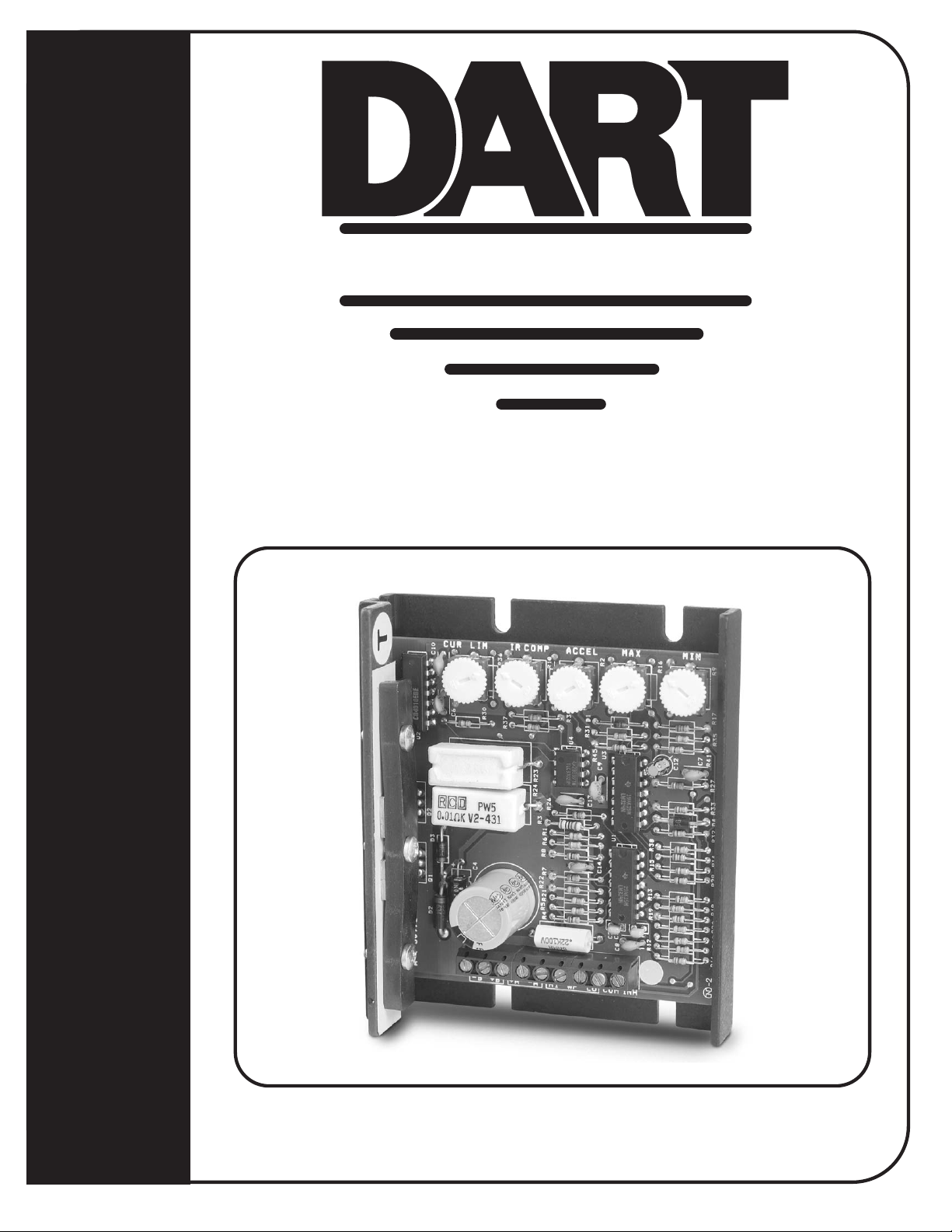
65E10 CONTROL SERIES
Zionsville, Indiana 46077
Phone (317) 873-5211
Fax (317) 873-1105
www.dartcontrols.com
A-5-3180E
Page 2

TABLE OF CONTENTS
WARRANTY .................................................................................................................................................................................1
STANDARD FEATURES .............................................................................................................................................................. 1
CONTROL DIMENSIONS .............................................................................................................................................................1
MOUNTING DIMENSIONS ........................................................................................................................................................... 2
65E10 MOUNTING ....................................................................................................................................................................... 2
INSTALLATION ............................................................................................................................................................................. 2
HOOK-UP DIAGRAMS................................................................................................................................................................. 2
65E10 HOOK-UP DIAGRAM .......................................................................................................................................................3
65E10 REVERSING HOOK-UP DIAGRAM ................................................................................................................................. 3
INHIBITING THE CONTROL ........................................................................................................................................................ 4
TRIMPOT ADJUSTMENTS .......................................................................................................................................................... 4
IN CASE OF DIFFICULTY ............................................................................................................................................................ 4
MODEL SELECTION ....................................................................................................................................................................5
SPECIFICATIONS ........................................................................................................................................................................ 5
WARRANTY
Dart Controls, Inc. (DCI) warrants its products to be free from defects in material and workmanship. The exclusive remedy
for this warranty is DCI factory replacement of any part or parts of such product which shall within 12 months after delivery to
the purchaser be returned to DCI factory with all transportation charges prepaid and which DCI determines to its satisfaction
to be defective. This warranty shall not extend to defects in assembly by other than DCI or to any article which has been
repaired or altered by other than DCI or to any article which DCI determines has been subjected to improper use. DCI
assumes no responsibility for the design characteristics of any unit or its operation in any circuit or assembly. This warranty
is in lieu of all other warranties, express or implied; all other liabilities or obligations on the part of DCI, including consequential damages, are hereby expressly excluded.
NOTE: Carefully check the control for shipping damage. Report any damage to the carrier immediately. Do not attempt to
operate the drive if visible damage is evident to either the circuit or to the electronic components.
All information contained in this manual is intended to be correct, however information and data in this manual are subject to
change without notice. DCI makes no warranty of any kind with regard to this information or data. Further, DCI is not responsible for any omissions or errors or consequential damage caused by the user of the product. DCI reserves the right to make
manufacturing changes which may not be included in this manual.
WARNING
Improper installation or operation of this control may cause injury to personnel or control failure. The control must be
installed in accordance with local, state, and national safety codes. Make certain that the power supply is disconnected
before attempting to service or remove any components!!! If the power disconnect point is out of sight, lock it in disconnected
position and tag to prevent unexpected application of power. Only a qualified electrician or service personnel should
perform any electrical troubleshooting or maintenance. At no time should circuit continuity be checked by shorting terminals
with a screwdriver or other metal device.
STANDARD FEATURES
●●
● Provides smooth variable speed capability for mobile equipment
●●
●●
● Maintains variable speed control as batteries discharge
●●
●●
● Adjustable maximum speed, minimum speed, current limit, I.R. compensation, and accel
●●
●●
● Inhibit terminal permits optional start-stop without breaking battery lines
●●
●●
● Speed potentiometer, knob, and dialplate included
●●
●●
● Increases range or running time of battery operated equipment through high efficiency
●●
CONTROL DIMENSIONS
MODEL WIDTH LENGTH DEPTH WEIGHT
inches (centimeters) oz. (gms.)
65E10 3.625 (9.21) 4.25 (10.76) 1.30 (3.30) 6.0 (170)
1
Page 3
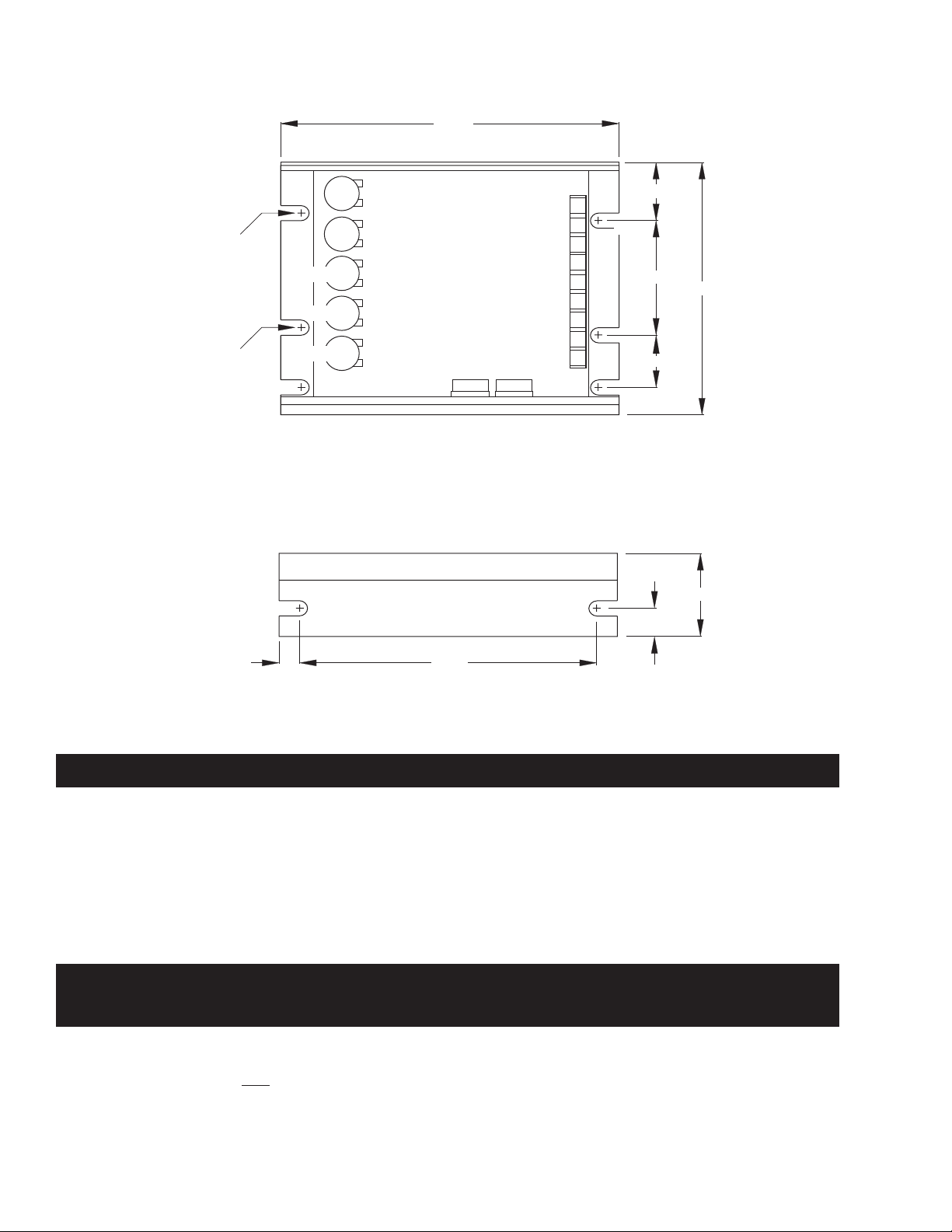
MOUNTING DIMENSIONS
65E10 MOUNTING
4.250"
.188" DIA.
(8 SLOTS)
11/32"
SLOT
DEPT
MIN
MAX
ACCEL
IR COMP
CUR LIM
TOP VIEW
P1
-9
-8
-7
-6
-5
-4
-3
-2
-1
.694"
1.750"
0.750”
.380"
3.625"
1.300"
.315"
3.750"
SIDE VIEW
Caution: Do not mount controller where ambient temperature is outside the range of -10° C (15° F) to 45° (115° F).
INSTALLATION
Before attempting to wire the control, make sure all power is disconnected. Recheck code designation to assure proper
voltage is present for the control. Caution should be used in selecting proper size of hook-up wire for current and voltage
drop.
HOOK-UP DIAGRAMS
WARNING:
DO NOT REVERSE POSITIVE AND NEGATIVE BATTERY LEADS. THIS WILL DAMAGE THE CONTROL.
TO CHANGE MOTOR DIRECTION, INTERCHANGE THE POSITIVE AND NEGATIVE ARMATURE LEADS.
Refer to the wiring diagrams below for proper connection of DC Voltage, Armature, and Speedpot wiring to the control.
CAUTION !! TURN POWER OFF WHILE MAKING CONNECTIONS.
To properly adjust the CURRENT LIMIT setting, a DC ammeter should be placed in series with the armature line. This meter
can be removed after the control is adjusted.
2
Page 4

Min Speed
Max Speed
Accel
I.R. Comp.
Current Limit
Min Speed
Max Speed
Accel
I.R. Comp.
Current Limit
65E10 HOOK-UP DIAGRAM
Optional
Inhibit
(see hook-up
below)
P1
Inhibit (P1-9)
Common (P1-8)
Pot Low (P1-7)
Pot Wiper (P1-6)
Pot High (P1-5)
-Arm (P1-4)
+Arm (P1-3)
+Battery (P1-2)
-Battery (P1-1)
Orange
Red
White
Customer
supplied
SPST switch
or relay
Battery
65E10 REVERSING HOOK-UP DIAGRAM
Optional
Inhibit
(see hook-up
below)
Inhibit (P1-9)
Common (P1-8)
Pot Low (P1-7)
Pot Wiper (P1-6)
Pot High (P1-5)
-Arm (P1-4)
+Arm (P1-3)
+Battery (P1-2)
-Battery (P1-1)
P1
Orange
Red
Customer
supplied
SPST switch
or relay
5KΩ
Speedpot
White
+
Battery
-
5KΩ
Speedpot
-
Motor
+
+
-
Customer supplied
3PDT Center-off
Center-blocked switch
Motor
Caution: When reversing a spinning motor, caution must be taken that the resulting current through the armature of
the motor does not exceed the overload ratings of the control, or the demagnetize rating of the motor being reversed
when using a permanent magnet DC motor.
3
Page 5

INHIBITING THE CONTROL
Using inhibit input - provides fast start-
stop by bypassing accel/decel circuit
Inhibit (P1-9)
Common (P1-8)
Pot Low (P1-7)
Pot Wiper (P1-6)
SPST Switch
open = run
close = stop
Pot High (P1-5)
P1
Note: Always use a shielded cable when connecting to the inhibit terminal. The shield of the cable should connect to the
Common terminal of the control.
Inhibit via speedpot - provides starting and
stopping through accel/decel parameters
SPST Switch
Inhibit (P1-9)
Common (P1-8)
Pot Low (P1-7)
Pot Wiper (P1-6)
Pot High (P1-5)
open = stop
close = run
Orange
Red
White
P1
5KΩ
Speedpot
TRIMPOT ADJUSTMENTS
Before the power is applied, the speed potentiometer and trimpots should be preset as follows:
TRIMPOT PRESET
1. Preset speedpot fully CCW, preset Max trimpot CW 1/2 way, preset Current Limit trimpot fully CW, preset Min trimpot
fully CCW, preset Accel trimpot CW 1/2 way, preset I.R. trimpot fully CCW.
DC power can now be applied to the system and the control adjusted as directed below:
TRIMPOT ADJUSTMENT
2. Increase the MIN trimpot in a clockwise direction until just before reaching an output voltage (deadband) or until the
desired minimum speed is reached.
3. Turn the Speedpot fully clockwise and adjust the MAX trimpot until the desired maximum speed is reached.
4. Adjust the ACCEL trimpot to achieve the desired soft start time. CW rotation will increase accel time.
5. Rotate the CURRENT LIMIT trimpot fully CCW. Apply a full load to the motor. While motor is stalled adjust the
CURRENT LIMIT trimpot CW until a desired current setting is obtained. Approximately 125% of rated motor current is
recommended.
6. Set speedpot to approximately 50% and note the motor RPM. Load the motor to normal load condition and adjust I.R.
trimpot CW until motor RPM is equal to unloaded speed.
IN CASE OF DIFFICULTY
PROBLEM POSSIBLE CAUSE(S) CORRECTIVE ACTION
Motor doesn’t run • Incorrect or no power
• Speedpot set at zero
• Worn motor brushes
• Current limit set too low
Motor “hunts” • Max trimpot set too high
• I.R. Comp. trimpot set too high
Motor runs at “full speed”
uncontrollable
Motor rotates in wrong direction • Motor armature hooked up backwards Reverse armature + and - leads
Motor stalls under a light load • Current limit trimpot improperly adjusted See “Trimpot Adjustments” - page 3-4
If a newly installed control will not operate, it is likely that a terminal or connection is loose. Check to make sure connections
are secure and correct. If the control is still inoperative, refer to the following chart for reference:
• Loose speedpot connections
• Min. or Max. trimpots not properly adjusted
• Possible control failure
Install proper service
Rotate speedpot fully CW
Replace motor brushes
Adjust current limit trimpot CW
See “Trimpot Adjustments” - page 3-4
See “Trimpot Adjustments” - page 3-4
Secure all connections
See “Trimpot Adjustments” - page 3-4
Send to Dart Controls, Inc.
4
Page 6

MODEL SELECTION
INPUT VOLTAGE OUTPUT VOLTAGE CONTINUOUS CURRENT MODEL NUMBER
12 VDC ± 15% 0 - 12 VDC 10 amps D.C. 65E10-12
24 VDC ± 15% 0 - 24 VDC 10 amps D.C. 65E10*
36 VDC ± 15% 0 - 36 VDC 10 amps D.C. 65E10*
* 24 volt and 36 volt units with the same current ratings are interchangeable (ie. 24 volt unit will operate with 36 volt input
and a 36 volt unit will operate with 24 volt input, same current rating).
SPECIFICATIONS
65E10
Load current (continuous) 10 amps
Speed adjustment
Speed range 30 : 1
Overload capacity 200% for 10 seconds; 150% for one minute
Current limit adjustable 100% to 200% of full motor load, up to 200% of control current rating
Acceleration adjustable - 0 to 10 seconds
Deceleration non-adjustable - 0.5 seconds
Maximum speed adjustable - 50 to 100% of base speed
Minimum speed adjustable - 0 to 30% of max speed
Connections Euro-style terminal block (14Ga. to 28Ga..)
Speed regulation
Operating temperature -10°C to +45°C (14°F to 113°F)
Package configuration
Internal operating frequency approximately 18K Hertz
5K Ω potentiometer or 0 to +10VDC input signal
1% of base speed via adjustable I.R. Compensation trimpot
black anodized aluminum extrusion
5
Page 7

NOTES:
6
Page 8

REPAIR PROCEDURE
In the event that a Product manufactured by Dart Controls Incorporated (DCI) is in need of
repair service, it should be shipped, freight paid, to: Dart Controls, Inc., 5000 W. 106th Street,
Zionsville, IN. 46077, ATTN: Repair Department.
Those orders received from anyone without and existing account with DCI will need to specify
if they will be paying COD or Credit Card (Master Card or Visa). This information is required
before work can begin. If you have an account with Dart your order will be processed according
to the terms listed on your account.
Completed repairs are returned with a Repair Report that states the problem with the control
and the possible cause. Repair orders are returned via UPS Ground unless other arrangements
are made. If you have further questions regarding repair procedures, contact your Dart Controls,
Inc. at 317-733-2133 Ext.460.
YOUR MOTOR SPEED CONTROL SOLUTIONS PROVIDER
125D SERIES
AC INPUT - VARIABLE DC OUTPUT
1/50 HP through 1.0 HP
700/COMMUTROL SERIES
DC BRUSHLESS
5 & 20 Amp for
12,24,& 36VDC Inputs
Dart Controls, Inc. is a designer, manufacturer, and
marketer of analog and digital electronic variable speed
drives, controls, and accessories for AC, DC, and DC
brushless motor applica-
tions.
Shown above is just a sampling of the expanded line of
Dart controls that feature the
latest in electronic technology
and engineering. Products are
manufactured in the U.S.A. at
our Zionsville (Indianapolis,
250G SERIES
AC INPUT - VARIABLE DC OUTPUT
1/50 HP through 2.0 HP
MDP SERIES
PROGRAMMABLE
CLOSED LOOP DC
SPEED CONTROL
Indiana) production and headquarters facility - with over
2,000,000 variable speed units
in the field.
In addition to the standard offthe-shelf products, you can select from a wide variety of options to customize controls for
your specific application. For
further information and application assistance, contact your
local Dart sales representative, stocking distributor, or
Dart Controls, Inc.
www.dartcontrols.com
ISO9001:2000 REGISTERED
DC INPUT - VARIABLE DC OUTPUT
CURRENT RATINGS OF 20, 40, AND
60 AMPS
DM SERIES
65 SERIES
FIELD PROGRAMMABLE
DIGITAL TACHOMETER
Dart Controls, Inc.
Manufacturer of high quality DC and AC motor speed
controls and accessories
since 1963.
P.O. Box 10
5000 W. 106th Street
Zionsville, Indiana 46077
Phone: (317) 733-2133
Fax: (317) 873-1105
 Loading...