


Cat. No. I570-E1-01
Re-Order from
omegamation.com
Omegamation
TM
1-888-55-OMEGA
1-888-55-66342
1-888-55-66342
USER’S MANUAL
SYSDRIVE MX2
SERIES
Multi-function Compact Inverter


Introduction
Thank you for choosing the multi-function Inverter 3G3MX2. This User's Manual (hereinafter
called "this manual") describes the parameter setting methods required for installation/wiring
and operation of the 3G3MX2 model, as well as troubleshooting and inspection methods.
z This manual should be delivered to the actual end user of the product.
z After reading this manual, keep it handy for future reference.
z This manual describes the specifications and functions of the product as well as the relations
between them. You should assume that anything not described in this manual is not possible
with the product.
z Intended readers
This manual is intended for those with knowledge of the workings of electricity (qualified
electric engineers or the equivalent), and also in charge of:
Introducing the control equipment
Designing the control system
Installing and/or connecting the control equipment
Field management
Introduction
SYSDRIVE MX2 Series USER'S MANUAL (3G3MX2-Axxxx)
1

Read and Understand this Manual
Read and Understand this Manual
Please read and understand this manual before using the product. Please consult your
OMRON representative if you have any questions or comments.
Warranty and Limitations of Liability
WARRANTY
OMRON's exclusive warranty is that the products are free from defects in materials and workmanship
for a period of one year (or other period if specified) from date of sale by OMRON.
OMRON MAKES NO WARRANTY OR REPRESENTATION, EXPRESS OR IMPLIED, REGARDING
NON-INFRINGEMENT, MERCHANTABILITY, OR FITNESS FOR PARTICULAR PURPOSE OF THE
PRODUCTS. ANY BUYER OR USER ACKNOWLEDGES THAT THE BUYER OR USER ALONE HAS
DETERMINED THAT THE PRODUCTS WILL SUITABLY MEET THE REQUIREMENTS OF THEIR
INTENDED USE. OMRON DISCLAIMS ALL OTHER WARRANTIES, EXPRESS OR IMPLIED.
LIMITATIONS OF LIABILITY
OMRON SHALL NOT BE RESPONSIBLE FOR SPECIAL, INDIRECT, OR CONSEQUENTIAL
DAMAGES, LOSS OF PROFITS OR COMMERCIAL LOSS IN ANY WAY CONNECTED WITH THE
PRODUCTS, WHETHER SUCH CLAIM IS BASED ON CONTRACT, WARRANTY, NEGLIGENCE, OR
STRICT LIABILITY.
In no event shall the responsibility of OMRON for any act exceed the individual price of the product on
which liability is asserted.
IN NO EVENT SHALL OMRON BE RESPONSIBLE FOR WARRANTY, REPAIR, OR OTHER CLAIMS
REGARDING THE PRODUCTS UNLESS OMRON'S ANALYSIS CONFIRMS THAT THE PRODUCTS
WERE PROPERLY HANDLED, STORED, INSTALLED, AND MAINTAINED AND NOT SUBJECT TO
CONTAMINATION, ABUSE, MISUSE, OR INAPPROPRIATE MODIFICATION OR REPAIR.
2
SYSDRIVE MX2 Series USER'S MANUAL (3G3MX2-Axxxx)

Read and Understand this Manual
Application Considerations
SUITABILITY FOR USE
OMRON shall not be responsible for conformity with any standards, codes, or regulations that apply to
the combination of products in the customer's application or use of the products.
At the customer's request, OMRON will provide applicable third party certification documents identifying
ratings and limitations of use that apply to the products. This information by itself is not sufficient for a
complete determination of the suitability of the products in combination with the end product, machine,
system, or other application or use.
The following are some examples of applications for which particular attention must be given. This is not
intended to be an exhaustive list of all possible uses of the products, nor is it intended to imply that the
uses listed may be suitable for the products:
• Outdoor use, uses involving potential chemical contamination or electrical interference, or conditions
or uses not described in this manual.
• Nuclear energy control systems, combustion systems, railroad systems, aviation systems, medical
equipment, amusement machines, vehicles, safety equipment, and installations subject to separate
industry or government regulations.
• Systems, machines, and equipment that could present a risk to life or property.
Please know and observe all prohibitions of use applicable to the products.
NEVER USE THE PRODUCTS FOR AN APPLICATION INVOLVING SERIOUS RISK TO LIFE OR
PROPERTY WITHOUT ENSURING THAT THE SYSTEM AS A WHOLE HAS BEEN DESIGNED TO
ADDRESS THE RISKS, AND THAT THE OMRON PRODUCTS ARE PROPERLY RATED AND
INSTALLED FOR THE INTENDED USE WITHIN THE OVERALL EQUIPMENT OR SYSTEM.
PROGRAMMABLE PRODUCTS
OMRON shall not be responsible for the user's programming of a programmable product, or any
consequence thereof.
SYSDRIVE MX2 Series USER'S MANUAL (3G3MX2-Axxxx)
3

Read and Understand this Manual
Disclaimers
CHANGE IN SPECIFICATIONS
Product specifications and accessories may be changed at any time based on improvements and other
reasons.
It is our practice to change model numbers when published ratings or features are changed, or when
significant construction changes are made. However, some specifications of the products may be
changed without any notice. When in doubt, special model numbers may be assigned to fix or establish
key specifications for your application on your request. Please consult with your OMRON representative
at any time to confirm actual specifications of purchased products.
Dimensions and weights are nominal and are not to be used for manufacturing purposes, even when
tolerances are shown.
DIMENSIONS AND WEIGHTS
PERFORMANCE DATA
Performance data given in this manual is provided as a guide for the user in determining suitability and
does not constitute a warranty. It may represent the result of OMRON's test conditions, and the users
must correlate it to actual application requirements. Actual performance is subject to the OMRON
Warranty and Limitations of Liability.
ERRORS AND OMISSIONS
The information in this manual has been carefully checked and is believed to be accurate; however, no
responsibility is assumed for clerical, typographical, or proofreading errors, or omissions.
4
SYSDRIVE MX2 Series USER'S MANUAL (3G3MX2-Axxxx)
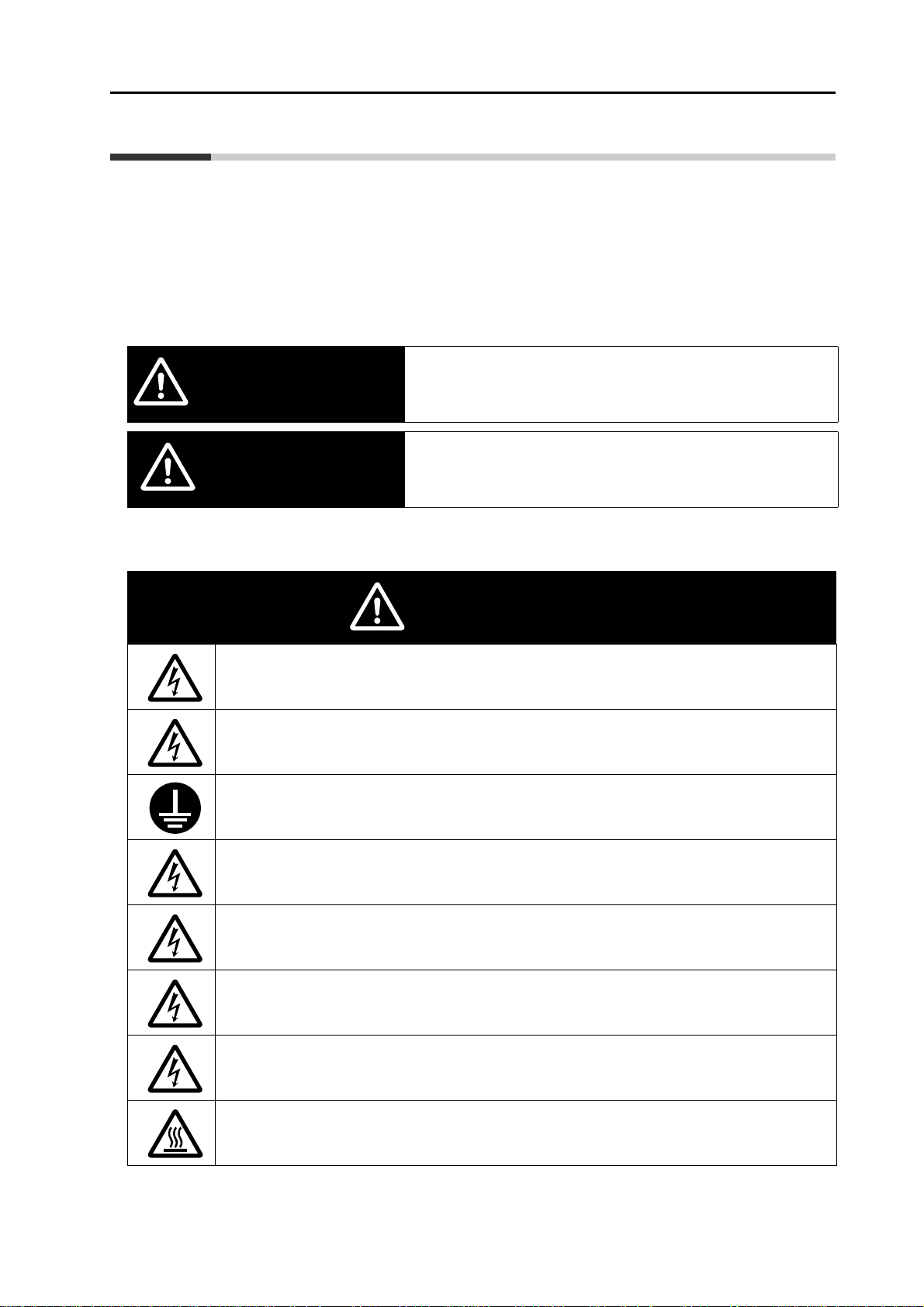
Safety Precautions
Indications and Meanings of Safety Information
In this user's manual, the following precautions and signal words are used to provide
information to ensure the safe use of the 3G3MX2 Inverter.
The information provided here is vital to safety. Strictly observe the precautions provided.
Meanings of Signal Words
Indicates a potentially hazardous situation which, if not avoided, will
WARNING
CAUTION
result in minor or moderate injury, or may result in serious injury or
death. Additionally there may be significant property damage.
Indicates a potentially hazardous situation which, if not avoided, may
result in minor or moderate injury or in property damage.
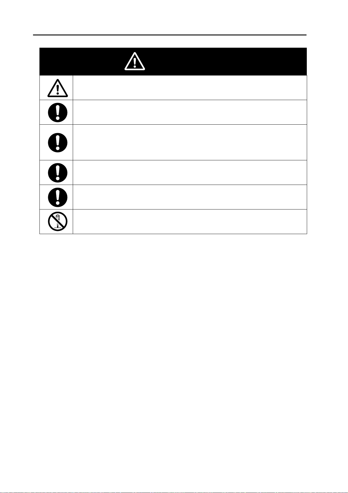
Safety Precautions
Alert Symbols in this Document
WARNING
Turn off the power supply and implement wiring correctly. Not doing so may result in a serious injury
due to an electric shock.
Wiring work must be carried out only by qualified personnel. Not doing so may result in a serious
injury due to an electric shock.
Be sure to ground the unit. Not doing so may result in a serious injury due to an electric shock or fire.
(200 V class: type-D grounding, 400 V class: type-C grounding)
Do not remove the terminal block cover during the power supply and 10 minutes after the power
shutoff.
Doing so may result in a serious injury due to an electric shock.
Do not operate the Digital Operator or switches with wet hands. Doing so may result in a serious
injury due to an electric shock.
Inspection of the Inverter must be conducted after the power supply has been turned off. Not doing
so may result in a serious injury due to an electric shock. The main power supply is not necessarily
shut off even if the emergency shutoff function is activated.
Do not change wiring, slide switches, or optional devices while power is being supplied.
Doing so may result in a serious injury due to an electric shock.
Do not touch the Inverter fins, braking resistors and the motor, which become too hot during the
power supply and for some time after the power shutoff. Doing so may result in a burn.
SYSDRIVE MX2 Series USER'S MANUAL (3G3MX2-Axxxx)
5
Safety Precautions
Do not connect resistors to the terminals (+1, P/+2, N/−) directly.
Doing so might result in a small-scale fire, heat generation or damage to the unit.
Install a stop motion device to ensure safety. Not doing so might result in a minor injury. (A holding
brake is not a stop motion device designed to ensure safety.)
Be sure to use a specified type of braking resistor/regenerative braking unit. In case of a braking
resistor, install a thermal relay that monitors the temperature of the resistor. Not doing so might result
in a moderate burn due to the heat generated in the braking resistor/regenerative braking unit.
Configure a sequence that enables the Inverter p ower to turn off when unusual overheating is
detected in the braking resistor/regenerative braking unit.
The Inverter has high voltage parts inside which, if short-circuited, might cause damage to itself or
other property. Place covers on the openings or take other precautions to make sure that no metal
objects such as cutting bits or lead wire scraps go inside when installing and wiring.
CAUTION
Take safety precautions such as setting up a molded-case circuit breaker (MCCB) that matches the
Inverter capacity on the power supply side. Not doing so might result in damage to property due to
the short circuit of the load.
Do not dismantle, repair or modify this product.
Doing so may result in an injury.
6
SYSDRIVE MX2 Series USER'S MANUAL (3G3MX2-Axxxx)

Precautions for Safe Use
Installation and Storage
Do not store or use the product in the following places.
Locations subject to direct sunlight.
Locations subject to ambient temperature exceeding the specifications.
Locations subject to relative humidity exceeding the specifications.
Locations subject to condensation due to severe temperature fluctuations.
Locations subject to corrosive or flammable gases.
Locations subject to exposure to combustibles.
Locations subject to dust (especially iron dust) or salts.
Locations subject to exposure to water, oil, or chemicals.
Locations subject to shock or vibration.
Transporting, Installation, and Wiring
Do not drop or apply strong impact on the product. Doing so may result in damaged parts or
malfunction.
Do not hold by the terminal block cover, but hold by the fins during transportation.
Do not connect an AC power supply voltage to the control input/output terminals. Doing so may
result in damage to the product.
Be sure to tighten the screws on the terminal block securely.
Wiring work must be done after installing the unit body.
Do not connect any load other than a three-phase inductive motor to the U, V, and W output
terminals.
Take sufficient shielding measures when using the product in the following locations. Not doing
so may result in damage to the product.
Locations subject to static electricity or other forms of noise.
Locations subject to strong magnetic fields.
Locations close to power lines.
Precautions for Safe Use
Main Circuit Power Supply
Confirm that the rated input voltage of the Inverter is the same as AC power supply voltage.
Operation and Adjustment
Be sure to confirm the permissible range of motors and machines before operation because the
Inverter speed can be changed easily from low to high.
Provide a separate holding brake if necessary.
Maintenance and Inspection
Be sure to confirm safety before conducting maintenance, inspection or parts replacement.
The life of the capacitor depends on ambient temperatures. Refer to the diagram of product life
specified in the manual. When the capacitor stops operating at the end of the product's life, the
Inverter must be replaced.
SYSDRIVE MX2 Series USER'S MANUAL (3G3MX2-Axxxx)
7

Precautions for Correct Use
Precautions for Correct Use
Installation
Mount the product vertically on a wall with the product's longer sides upright.
The material of the wall has to be nonflammable such as a metal plate.
Restart after Trip
Do not come close to the machine when using the Restart During Momentary Power Interruption
function because the machine may abruptly start when stopped by an alarm.
Be sure to confirm the RUN signal is turned off before resetting the alarm because the machine
may abruptly start.
Operation Stop Command
Provide a separate emergency stop switch because the STOP key on the Digital Operator is valid
only when function settings are performed.
When checking a signal during the power supply and the voltage is erroneously applied to the
control input terminals, the motor may start abruptly. Be sure to confirm safety before checking a
signal.
Maintenance and Parts Replacement
The Inverter consists of many parts, and these parts must operate properly in order to make full
use of the designed functions of the Inverter. Among the electronic components, there are some
that require maintenance depending on their usage conditions. In order to keep the Inverter
operating normally over a long period of time, it is necessary to perform periodic inspections and
replace parts according to their service life.
Product Disposal
Comply with the local ordinance and regulations when disposing of the product.
8
SYSDRIVE MX2 Series USER'S MANUAL (3G3MX2-Axxxx)
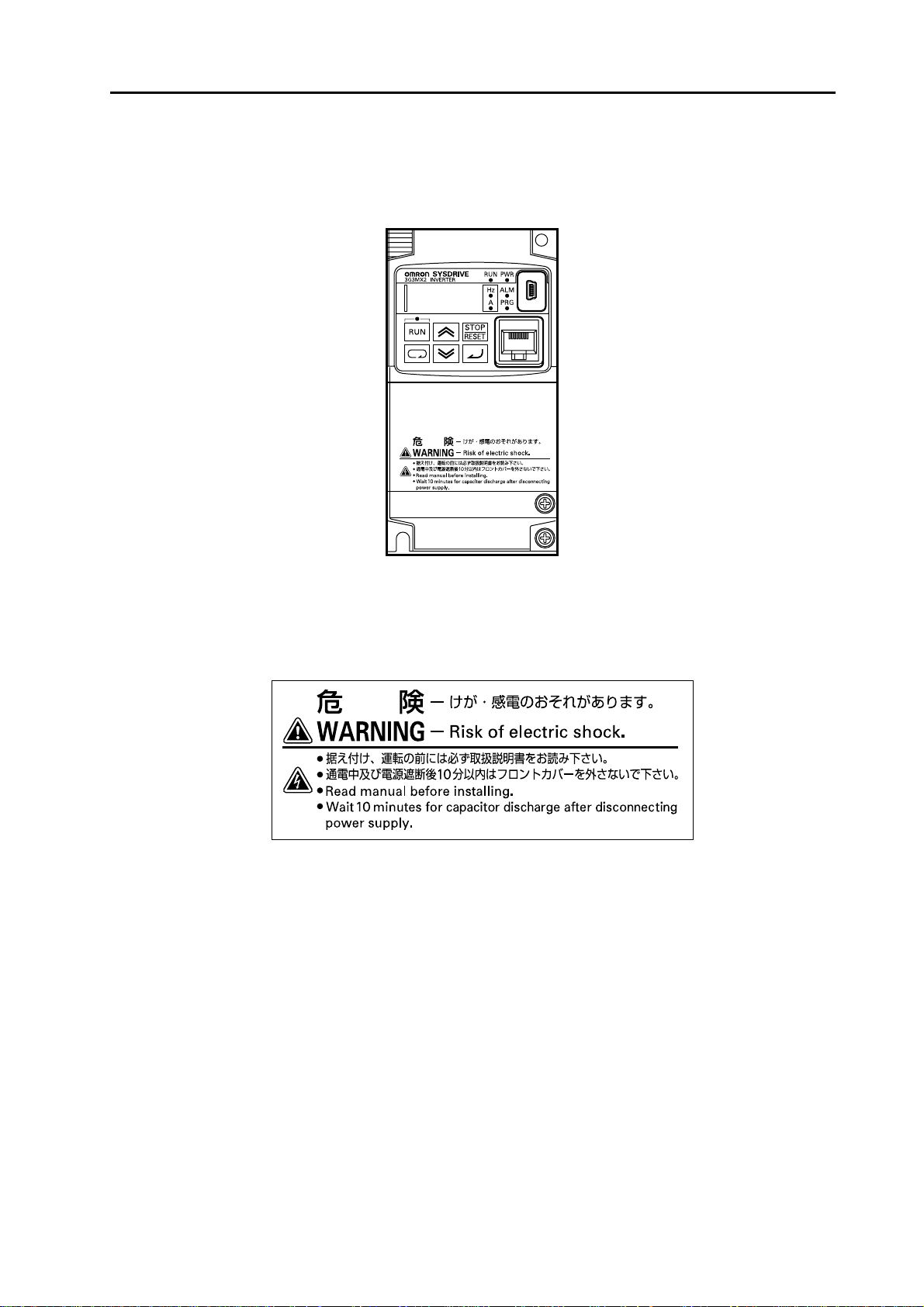
Warning Labels
Warning labels are located on the Inverter as shown in the following illustration.
Be sure to follow the instructions.
Precautions for Correct Use
Warning Description
SYSDRIVE MX2 Series USER'S MANUAL (3G3MX2-Axxxx)
9
Checking Before Unpacking
Checking Before Unpacking
Checking the Product
On delivery, be sure to check that the delivered product is the Inverter 3G3MX2 model that you
ordered.
Should you find any problems with the product, immediately contact your nearest local sales
representative or OMRON sales office.
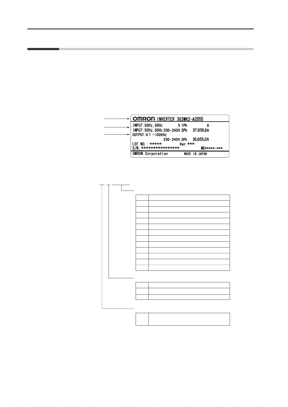
Checking the Nameplate
Inverter model
Input specifications
Output specifications
Checking the Model
3G3MX2-A2055
Maximum applicable motor capacity (CT rating)
0.1 kW
001
0.2 kW
002
0.4 kW
004
0.75 kW
007
1.5 kW
015
2.2 kW
022
030
3.0 kW
037
3.7 kW
040
4.0 kW
055
5.5 kW
075
7.5 kW
110
11 kW
150
15 kW
Voltage class
1-phase 200 V AC (200 V class)
B
3-phase 200 V AC (200 V class)
2
3-phase 400 V AC (400 V class)
4
Enclosure rating
Panel-mounting (IP10 min.) or closed
A
wall-mounting models
Checking the Accessories
Note that Instruction manual is the only accesso ry includ ed w ith the 3G3MX2 model.
Mounting screws and other necessary parts must be provided by the user.
10
SYSDRIVE MX2 Series USER'S MANUAL (3G3MX2-Axxxx)
Revision History
A manual revision code appears as a suffix to the catalog number located at the lower left of
the front and back covers.
Cat.No. I570-E1-01
Revision History
Revision code
Revision
code
01 September 2009 First printing
Revision
date
Changes and revision pages
SYSDRIVE MX2 Series USER'S MANUAL (3G3MX2-Axxxx)
11

About This Manual
About This Manual
This User's Manual is compiled chapter by chapter for user's convenience as follows.
Understanding the following configuration ensures more effective use of the product.
Chapter 1 Overview Describes features and names of parts.
Provides external dimensions, installation dimensions, peripheral
Chapter 2 Design
device design/selection instructions, and other information necessary
for design.
Overview
Chapter 3 Operation
Chapter 4 Parameter List List of parameters set via Digital Operator.
Chapter 5 Functions Describes the functions of the Inverter.
Chapter 6
Chapter 7
Chapter 8
Chapter 9 Specifications
Appendix
Communication
Function
Maintenance
Operations
Inspection and
Maintenance
Describes names of parts, the Inverter's operations, including how to
use the keys on the Digital Operator, and the monitor function.
Describes the Modbus-RTU communication.
Describes the causes and their countermeasures if the Inverter fails,
including the solutions to possible troubles (troubleshooting).
Describes items for periodical inspection and/or maintenance for the
Inverter.
Provides Inverter specifications, as well as the specifications and
dimensions of peripheral devices.
Describes the derating chart, capacitor life curve, compliance with
international standards and index.
12
SYSDRIVE MX2 Series USER'S MANUAL (3G3MX2-Axxxx)


Contents
Introduction...................................................................................... 1
Read and Understand this Manual.................................................. 2
Safety Precautions........................................................................... 5
Precautions for Safe Use................................................................. 7
Precautions for Correct Use ............................................................ 8
Checking Before Unpacking............................................................ 10
Revision History............................................................................... 11
About This Manual........................................................................... 12
Chapter1 Overview
1-1 Functions......................................................................................................1-1
1-2 Appearance and Names of Parts.................................................................1-4
Chapter2 Design
2-1 Installation....................................................................................................2-1
2-2 Wiring...........................................................................................................2-6
Chapter3 Operation
3-1 Name of Parts of the Digital Operator..........................................................3-1
3-2 Operation Method.........................................................................................3-7
3-3 Test Run.....................................................................................................3-10
3-4 Tripping ......................................................................................................3-12
Chapter4 Parameter List
4-1 Monitor Mode ...............................................................................................4-1
4-2 Function Mode..............................................................................................4-4
Chapter5 Functions
5-1 Monitor Mode ...............................................................................................5-1
5-2 Basic Functions..........................................................................................5-13
5-3 Input/Output Terminals.......................................... .... .... .... ..... .... .... .... .... ....5-29
5-4 Analog Signal................................... .... .... .... ..... .... .... .... .... ..... .... .... .... .... ....5-37
5-5 Settings Relating to Control Method.......................... .................................5-46
5-6 Operation Functions...................................................................................5-56
5-7 Digital Operator/Operation Functions..................................... .... .... .... .... ....5-84
5-8 Restart Functions.......................................................................................5-94
5-9 Functions Relating to Protections, Warnings and Various Output Signals5-110
5-10 Brake Settings..........................................................................................5-135
5-11 Sensorless Vector Control........................................................................5-144
5-12 Simple Position Control Function.............................................................5-157
5-13 Safety Function ........................................................................................5-167
5-14 Other Functions............................................ ..... .... .... .... .... ..... .... .... .... .... ..5-171
14
SYSDRIVE MX2 Series USER'S MANUAL (3G3MX2-Axxxx)

Contents
Chapter6 Communication Function
6-1 Communication Specifications..................................................................... 6-1
6-2 RS-485 Port Specifications and Connection................................................6-2
6-3 List of Modbus Communication (Modbus-RTU) Parameters....................... 6-3
6-4 Modbus Communication (Modbus-RTU) Protocol....................................... 6-4
6-5 Explanation of Each Parameter No.............................................................. 6-8
6-6 To Save the Change to the Holding Register (Enter Command)............... 6-19
6-7 Co-Inverter Communication......... .... .... .... ..... .... .... .... .... ............................. 6-22
6-8 List of Modbus Communication (Modbus-RTU) Data................................ 6-27
Chapter7 Maintenance Operations
7-1 Error Display and Remedial Actions............................................................7-1
7-2 Troubleshooting........................................................................................... 7-9
Chapter8 Inspection and Maintenance
8-1 Inspection and Maintenance............ .... .... ..... .... .... .... .... ..... .... .... .... .... ..... .... . 8-1
Chapter9 Specifications
9-1 Standard Specification List .......................................................................... 9-1
9-2 External Dimensions.................................................................................... 9-6
9-3 Options....................................................................................................... 9-12
Appendix
Appendix-1 Derating Table ...................................................... ..... .... .... .... .... ..... .App-1
Appendix-2 Smoothing Capacitor Life Curve......................................................App-7
Appendix-3 Life Alarm Output .............................................................................App-8
Appendix-4 Notes on Compliance with EC Directives and UL/cUL Standards...App-9
INDEX
SYSDRIVE MX2 Series USER'S MANUAL (3G3MX2-Axxxx)
15


Overview
Describes the features, operating procedures, performance specifications and
other aspects of this Unit.
1-1 Functions...............................................................................1-1
1-2 Appearance and Names of Parts.........................................1-4
1
3G3MX2 Inverter Models................................................................1-1
International Standards (EC Directives and UL/cUL Standards)....1-2
High-performance, Multi-function Compact Inverter Supporting
Wide-ranging Applications........................................... .... ... ... ... ... ... 1-2
SYSDRIVE MX2 Series USER'S MANUAL (3G3MX2-Axxxx)

1-1 Functions
1-1 Functions
3G3MX2 Inverter Models
1
Overview
Rated voltage
3-phase 200 VAC IP20 0.1kW 0.2 kW 3G3MX2-A2001
3-phase 400 VAC IP20 0.4 kW 0.75 kW 3G3MX2-A4004
Enclosure
ratings
Max. applicable motor capacity
Model
CT: Heavy load VT: Light load
0.2 kW 0.4 kW 3G3MX2-A2002
0.4 kW 0.75 kW 3G3MX2-A2004
0.75 kW 1.1 kW 3G3MX2-A2007
1.5 kW 2.2 kW 3G3MX2-A2015
2.2 kW 3.0 kW 3G3MX2-A2022
3.7 kW 5.5 kW 3G3MX2-A2037
5.5 kW 7.5 kW 3G3MX2-A2055
7.5 kW 11 kW 3G3MX2-A2075
11 kW 15 kW 3G3MX2-A2110
15 kW 18.5 kW 3G3MX2-A2150
0.75 kW 1.5 kW 3G3MX2-A4007
1.5 kW 2.2 kW 3G3MX2-A4015
2.2 kW 3.0 kW 3G3MX2-A4022
3.0 kW 4.0 kW 3G3MX2-A4030
4.0 kW 5.5 kW 3G3MX2-A4040
1-1
5.5 kW 7.5 kW 3G3MX2-A4055
7.5 kW 11 kW 3G3MX2-A4075
11 kW 15 kW 3G3MX2-A4110
15 kW 18.5 kW 3G3MX2-A4150
1-phase 200 V AC IP20 0.1 kW 0.2 kW 3G3MX2-AB001
0.2 kW 0.4 kW 3G3MX2-AB002
0.4 kW 0.55 kW 3G3MX2-AB004
0.75 kW 1.1 kW 3G3MX2-AB007
1.5 kW 2.2 kW 3G3MX2-AB015
2.2 kW 3.0 kW 3G3MX2-AB022
SYSDRIVE MX2 Series USER'S MANUAL (3G3MX2-Axxxx)

1-1 Functions
International Standards (EC Directives and UL/cUL Standards)
The 3G3MX2 Inverter meets the EC Directives and UL/cUL standard requirements for
worldwide use.
Classification Applicable standard
EC Directives EMC directive EN61800-3: 2004
Low-voltage directive EN61800-5-1: 2003
UL/cUL Standards UL508C
High-performance, Multi-function Compact Inverter Supporting Wide-ranging Applications
Powerful Torque Ideal for a Variety of Applications
1
Overview
High starting torque
With the sensorless vector control and au to-tuning functions, this Unit ensures high star ting
torque of 200% at 0.5 Hz.
Note. The frame may have to be raised depending on the condition.
Overload limit/Overcurrent Suppression function
(1)The Inverter monitors the motor curren t duri n g acceleration or constant speed op eration in
order to lower output frequency automatically.
(2)This function suppresses significant change in current caused by rapid acceleration, etc.
Acceleration will be suppressed temporarily if the output current reaches approx. 180% of
the rated current during acceleration.
Various Applications
Safety Function
Conforming to stop category 0 und er IEC60204-1 and the ISO13849-1: 2006 (PLd) standard
(certification pending)
Simple Position Control Function
(1)Comes standard with the pulse input functions.
(2)Supporting simple positioning to a maximum of 8 points by setting the position command,
speed reference and acceleration/deceleration time to parameters.
Comes Standard with RS-485 (Modbus-RTU)
(1)Comes standard with the Modbus-RTU communication function to communicate with, and
also read/write various parameters from/to, the host equipment.
Broadcasting from the host equipment is also supported.
(2)Transfer Speed: Supporting speeds up to 115.2 kbps
(3)Co-inverter communication is also supported.
Side-by-Side (Zero Clearance) Installation
Since the Inverter can be installed with its right or left face contacting a wall or other structure ,
the installation space can be reduced.
SYSDRIVE MX2 Series USER'S MANUAL (3G3MX2-Axxxx)
1-2

1
Overview
1-1 Functions
Note. The carrier frequency, etc. must be derated depending on the model.
Password Function
Comes with the password function to prevent reading or changing of parameters without
proper access privileges.
1-3
SYSDRIVE MX2 Series USER'S MANUAL (3G3MX2-Axxxx)

1-2 Appearance and Names of Parts
1-2 Appearance and Names of Parts
1-phase 200 V 0.1, 0.2, 0.4 kW
3-phase 200 V 0.1, 0.2, 0.4, 0.75 kW
Even if the W × H
dimension is the same, the
D dimension for the
cooling fin varies
depending on the capacity.
H
D
(3)
1
W
(6)
1-phase 200 V 0.75, 1.5, 2.2 kW
3-phase 200 V 1.5, 2.2 kW
3-phase 400 V 0.4, 0.75, 1.5, 2.2, 3.0 kW
Overview
(5)
(4)
(7)
(1)
(2)
(3)
Even if the W × H
dimension is the same, the
D dimension for the
cooling fin varies
depending on the capacity.
H
D
W
(6)
(1) Cooling fan cover (5 ) Te rm in al blo ck cove r
(2) Cooling fan (6) Optional board cover
(3) Cooling fin (7) Backing plate
(4) Main housing
Note: • 3-phase 200 V/0.75 kW models come with a cooling fan.
1-phase 200 V/0.75 kW models and 3-phase 400 V/0.4 kW/0.75 kW models do not come with a cooling fan.
•
SYSDRIVE MX2 Series USER'S MANUAL (3G3MX2-Axxxx)
(5)
(4)
(7)
1-4
1
1-2 Appearance and Names of Parts
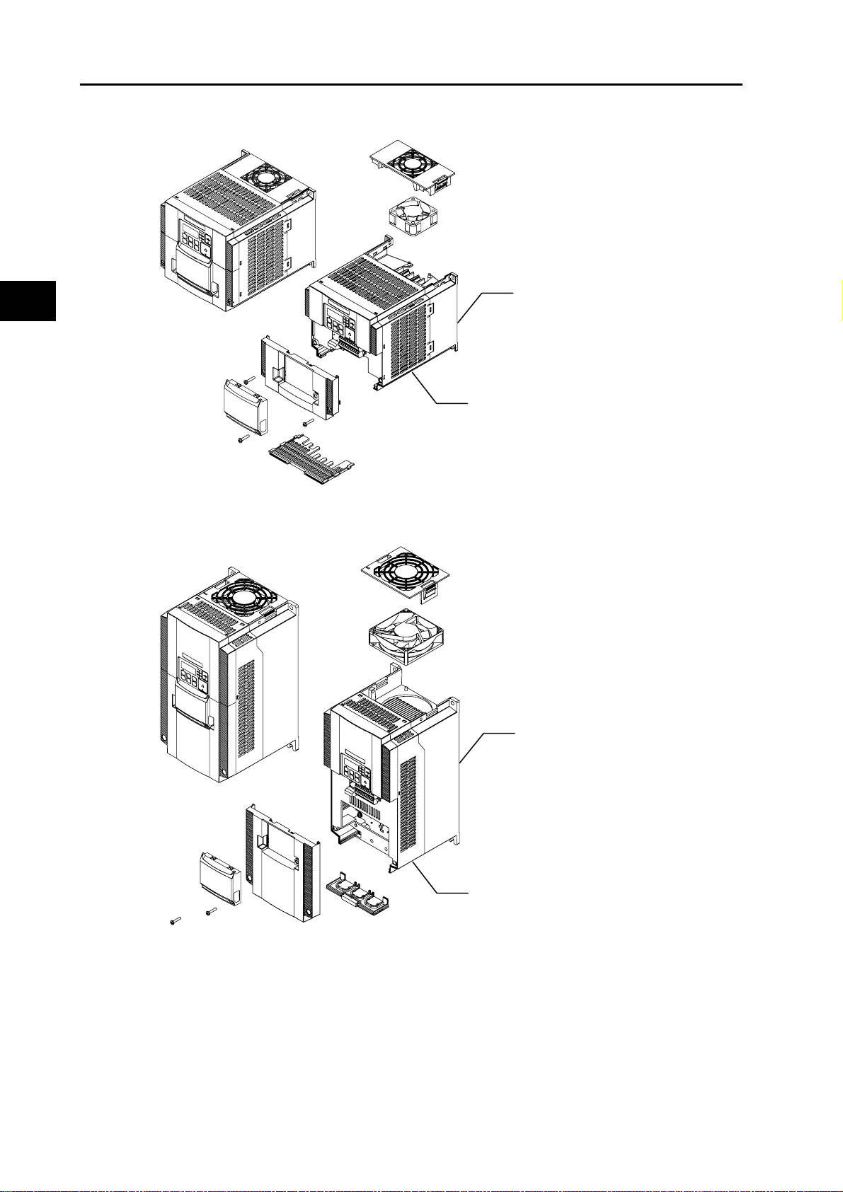
3-phase 200 V 3.7 kW
3-phase 400V 4.0 kW
(1)
(2)
(3)
(5)
Overview
(6)
3-phase 200 V 5.5, 7.5 kW
3-phase 400 V 5.5, 7.5 kW
(4)
(7)
(1)
(2)
(3)
1-5
(5)
(6)
(4)
(7)
(1) Cooling fan cover (5) Terminal block cover
(2) Cooling fan (6) Optional board cover
(3) Cooling fin (7) Backing plate
(4) Main housing
SYSDRIVE MX2 Series USER'S MANUAL (3G3MX2-Axxxx)
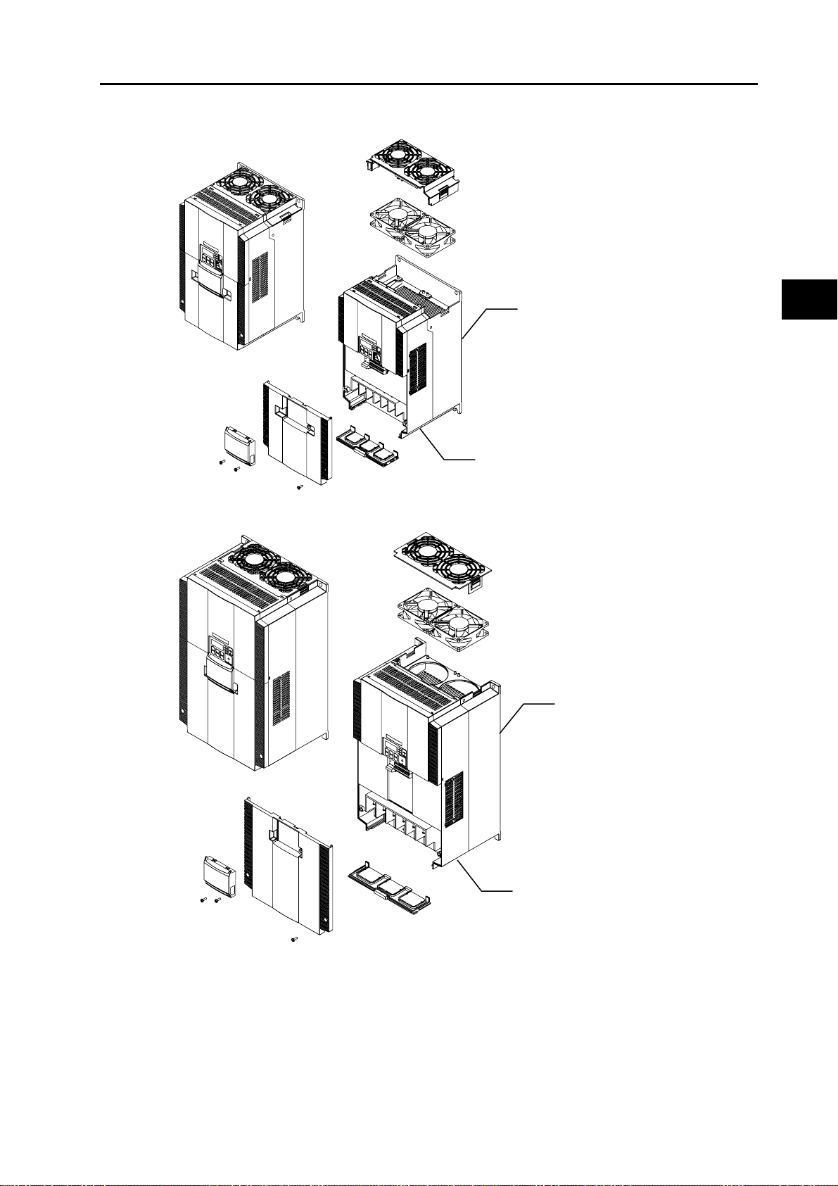
3-phase 200 V 11 kW
3-phase 400 V 11, 15 kW
1-2 Appearance and Names of Parts
(1)
(2)
(5)
(6)
3-phase 200 V 15 kW
(7)
(4)
(3)
1
Overview
(1)
(2)
(3)
(5)
(6)
(1) Cooling fan cover (5 ) Te rm in al blo ck cove r
(2) Cooling fan (6) Optional board cover
(3) Cooling fin (7) Backing plate
(4) Main housing
SYSDRIVE MX2 Series USER'S MANUAL (3G3MX2-Axxxx)
(4)
(7)
1-6


Design
Describes the name and function of each part, installation method, wiring method ,
etc.
2-1 Installation.............................................................................2-1
Precautions for Safe Use................................................................2-1
Precautions for Correct Use...................... ... ... .... ............................2-2
Installation Environment..................................................................2-2
Backing Plate.. ... ... .... ... .......................................... ... ... .... ... ............2-3
Installation/Removal Method of the Terminal Block Cover.............2-4
Names of Parts Inside the Terminal Block Cover ...........................2-5
2-2 Wiring.....................................................................................2-6
Connection Diagram................................. ... ... ................................2-6
Wiring the Main Circuit Terminals.................................................2-10
Wiring Control Circuit Terminals...................................................2-18
Connection to Programmable Controller (PLC) ............................2-22
2
SYSDRIVE MX2 Series USER'S MANUAL (3G3MX2-Axxxx)

2
2-1 Installation
2-1 Installation
Precautions for Safe Use
Installation and Storage
Do not store or use the product in the following places.
Locations subject to direct sunlight.
Locations subject to ambient temperature exceeding the specifications.
Locations subject to relative humidity exceeding the specifications.
Locations subject to condensation due to severe temperature fluctuations.
Locations subject to corrosive or flammable gases.
Locations subject to exposure to combustibles.
Locations subject to dust (especially iron dust) or salts.
Locations subject to exposure to water, oil, or chemicals.
Locations subject to shock or vibration.
Design
Transportation, Installation, and Wiring
Do not drop or apply any strong impact to the Inverter to avoid damage to the parts and/or
the Inverter.
When transporting the Inverter, hold the fin, not the front cover or terminal block cover.
Do not connect an AC power supply to the control I/O terminals. Doing so may cause damage
to the Inverter.
Be sure to tighten the screws on the terminal block securely.Perform the wiring after installing
the Inverter.
Do not connect any load other than the 3-phase induction motor to the output terminals (U/
T1, V/T2, W/T3) of the Inverter.
Take appropriate and sufficient countermeasures when using the Inverter in the following
locations.Not doing so may result in damage to the Inverter.
Locations subject to static electricity or other forms of noise.
Locations subject to strong electromagnetic fields.
Locations close to power supplies.
Main Circuit Power Supply
Confirm that the rated input voltage of the Inverter matches the AC power supply voltage.
2-1
SYSDRIVE MX2 Series USER'S MANUAL (3G3MX2-Axxxx)
Precautions for Correct Use
Installation
Install the Inverter vertically on a wall.
Install the Inverter on a nonflammable wall surface material, like metal.
2-1 Installation
2
Design
Installation Environment
Make sure the ambient temperature remains within the rated range (−10 to 50°C). Take note that if
the ambient temperature reaches or exceeds 40
be derated. If the Inverter is used in an environment exceeding the allowable operating temperature
range, the product life of the Inverter (specifically, the capacitor) will be shortened.
Measure and check the temperature approx. 5 cm from the bottom center of the Inver ter body.
Provide sufficient space around the Inverter because it can become very hot (up to 150°C or so).
Keep the Inverter away from heating elements (such as a Braking Resistor, reactor, etc.).
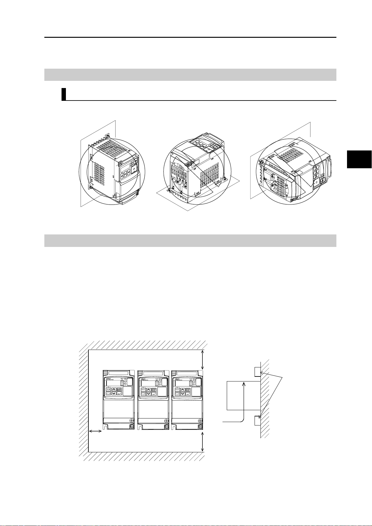
Although side-by-side installation is possible. The ambient temperature of the installation site
must not exceed 40°C and the carrier frequency and output current must be derated if side-byside installation is used.
°
C, the carrier frequency and output current must
100 mm or more
Air flow
Inverter
Provide sufficient
space so that the top
and bottom wiring
ducts, etc. will not
obstruct the flows of
cooling air.
Wall
50 mm or more
Do not install the Inverter in hot, humid sites or other sites subject to frequent bedewing.
Make sure that the humidity in the installation site is within the allowable operating range ( 20%
to 90% RH), as defined in the standard specifications.
SYSDRIVE MX2 Series USER'S MANUAL (3G3MX2-Axxxx)
100 mm or more
2-2
2-1 Installation
In particular, make sure that the installation site is free from condensation.If condensed water
adheres to the Inverter's internal parts, the electronic components may short-circuit, causing
failure of the Inverter.In addition to avoiding condensation, avoid installing the Inverter under
direct sunlight.
Avoid an environment where the Inverter may be exposed to dust, gases (corrosive, explosive,
and/or flammable), grinding fluid mis t, o r s alt. If a foreign object (e.g. dust) enters the Inverter,
it could result in failure of the Inverter.If using the Inverter in a dusty place, take appropriate
measures. (For example, place the Inverter in a closed panel.)
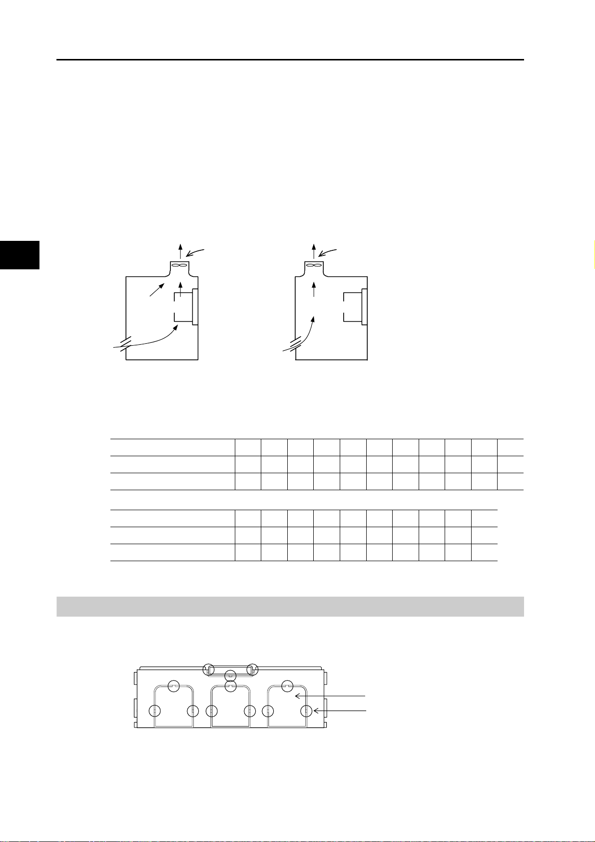
When several Inverters are installed in a panel and a ventilation fan is mounted in the panel,
be careful about the layout of the Inverters and the air intake apertures.Depending on the
layout, the Inverter's cooling effect may deteriorate, resulting in an increase in the ambient
temperature.
2
Design
Ventilation fan
Inverter
(Good example) (Bad example)
Ventilation fan
Inverter
Heat Radiation from Inverter
1-phase/3-phase 200 V
Inverter capacity (kW) 0.1 0.2 0.4 0.75 1.5 2.2 3.7 5.5 7.5 11 15
Load with 100% loss (W) 12 22 30 48 79 104 154 229 313 458 625
Efficiency at rated output (%) 89.5 90 93 94 95 95.5 96 96 96 96 96
3-phase 400 V
Inverter capacity (kW) 0.4 0.75 1.5 2.2 3.0 4.0 5.5 7.5 11 15
Load with 100% loss (W) 35 56 96 116 125 167 229 296 411 528
Efficiency at rated output (%)9293949596969696.296.496.6
Backing Plate
With a model of 5.5 kW or higher ca pacit y, cu t off the connection points between the backing
plate and unnecessary portions with nippers or a wire cutter when running cables.
2-3
Unnecessary portions
Connection points
SYSDRIVE MX2 Series USER'S MANUAL (3G3MX2-Axxxx)

Installation/Removal Method of the Terminal Block Cover
1. Removal method
2-1 Installation
Loosen the screw(s) (1 or 2
locations) securing the
terminal block cover.
While pressing here in the direction
of the arrow, pull the terminal block
cover downward to remove.
The terminal block cover is secured with one screw at the bottom right for 3.0 kW and smaller
models, or with two screws on both sides for 3.7 kW and larger models.
The optional board cover is affixed with screws onto the terminal block cover, but it is not
affixed onto the main unit. Accordingly, the terminal block cover can be removed without
removing the optional board cover.
While pressing the bottom of the
terminal block cover in the direction
of the arrow, pull the terminal block
cover downward to remove.
2
Design
8.8.8.8.
Optional board cover
8.8.8.8.
Terminal block cover
Terminal block cover screw
(1 location for 3.0 kW and smaller models)
Terminal block cover screw
(2 locations for 3.7 kW and larger models)
2. Installation method
Follow the removal procedure in reverse. Set the top side of the terminal block cover onto the
main unit and push in the cover until you hear a "click" sound.
SYSDRIVE MX2 Series USER'S MANUAL (3G3MX2-Axxxx)
2-4

2-1 Installation
Names of Parts Inside the Terminal Block Cover
2
Design
Modbus-RTU Termination resistor selector switch
OFF
(Factory default)
Connector for optional board
Multi-function contact terminal block
CHARGE indicator
Name Description
Modbus-RTU
Termination resistor
selector switch
Safety function
selector switch
EDM function
selector switch
USB connector Use this mini-B USB connector to connect a PC.
Connector for
Digital Operator
Use this Terminal Resistor selector switch for RS-485 terminals on the control circuit
terminal block. When this switch is turned ON, the internal 200
Turn this switch ON when using the safety function. Turn OFF the power before
turning this switch ON/OFF.For details, refer to "Safety Function" on page 5-167.
Turn this switch ON when using the EDM output of the safety function. Turn OFF
the power before turning this switch ON/OFF.For details, refer to "Safety Function"
on page 5-167.
Even when the Inverter is being operated by a PC, etc., via USB connection, it can
still be operated using the Digital Operator.
Use this connector to connect the Digital Operator.
ON
Safety function selector switch
Disable
(Factory default)
Connector for Digital Operator (RJ45)
P1 terminal
(Factory default)
Enable
USB connector (mini-B)
EDM function selector switch
EDM output
Control circuit terminal block A
Control circuit terminal block B
Main circuit terminal block
Ω
Resistor is connected.
2-5
Connector for
optional board
Control circuit
terminal blocks A
and B
Multi-function
contact terminal
block
Main circuit
terminal block
CHARGE
indicator (Charge
indicator LED)
Use this connector to mount the optional board. (The optional board will be released
soon.)
These terminal blocks are used to connect various digital/analog input and output
signals for inverter control, etc.
Use this SPDT contact terminal block for relay outputs.
Use this terminal block to connect an output to the motor and Braking Resistor, etc.
Also, use this terminal block to connect the inverter to the main power supply.
This LED indicator is lit if the DC voltage of the main circuit (between terminals P/
+2 and N/−) remains approx. 45 V or above after the power has been cut off. Before
wiring, etc. confirm that the Charge LED indicator is turned OFF.
Note. Refer to Chapter 3 "Operation" for the display and operating controls.
SYSDRIVE MX2 Series USER'S MANUAL (3G3MX2-Axxxx)

2-2 Wiring
Connection Diagram
ELB
Single-phase
3-phase
power
supply
If any external source-logic
output equipment or power
supply is used, refer to
"Connection to
Programmable Controllers
(PLC)" on page 2-22.
MC
Shorting
bar
R/L1
S/L2
T/L3
P24P24
PSC
SC
24VDC
U/T1
V/T2
W/T3
+1
P/+2
RB
Shorting bar
DC reactor
2-2 Wiring
M
Motor
To connect the DC
reactor, remove
the shorting bar.
2
Design
Multi-function
input
(7 contact
points)
2 kΩ or more
10 VDC power
supply (7 mA Max.)
Analog voltage input
0 to 10 V (10 bits)
Analog current input
4 to 20 mA (10 bits)
Pulse input
5 to 24 VDC
(32 kHz Max.)
Analog voltage
output 0 to 10 V
(10 bits)
Pulse output
0 to 10 VDC
(32 kHz Max.)
S7/EB
S6
S5/TH
S4/GS2
S3/GS1
S2
S1
FS
FV
FI
RP
AM
MP
SC
N/−
MC
MA
MB
P2
P1/EDM
PC
RS+
RS−
Braking Resistor*1
Multi-function
relay output
Multi-function output
(2 terminals)
Serial communication port
(RS-485/Modbus-RTU)
When using a Regenerative Braking Unit
Regenerative
P/+2
RB
N/
−
Braking Unit*1
P
N
Braking Resistor*1
P
RB
Note 1: Connect a single-phase 200 V AC input to terminals L1 and N.
Note 2: Factory default settings for relay output are NC contact for MA and NO contact for MB.
SYSDRIVE MX2 Series USER'S MANUAL (3G3MX2-Axxxx)
Class D (200 V class)
Class C (400 V class)
*1 Option
2-6

2-2 Wiring
Main Circuit Terminals
2
Design
Terminal
symbol
R/L1 Main power supply
S/L2
T/L3
U/T1 Inverter output
V/T2
W/T3
+1 DC reactor
P/+2
P/+2 Braking Resistor
RB
P/+2 Regenerative
N/−
G Ground terminal This is a ground terminal. Connect this terminal to the ground.
Terminal name Description
Connect the input AC power supply.In the case of a 1-phase 200 V
input terminal
terminal
connection terminal
connection terminal
braking unit
connection terminal
power supply, connect to L1 and N.
Connect a 3-phase motor.
Remove the shorting bar between terminals +1 and P/+2, and
connect the optional DC reactor.
Connect optional braking resistors. (If a braking torque is required)
Connect optional regenerative braking units. (When braking torque
is required or the built-in braking circuit is not sufficient)
Provide Class D grounding for 200 V class models, and class C
grounding for 400 V class models.
On 200 V class models of 3.7 kW or below and 400 V class models
of 4.0 kW or below, the ground terminal is located on the cooling fin.
Control Circuit Terminals
Power
supply
Frequency
Analog
setting
input
Terminal
symbol
SC Input signal
FS Frequency
FV
FI
Terminal name Description Specifications
common
reference
power supply
Frequency
reference input
terminal (analog
voltage input)
Frequency
reference
terminal (analog
current input)
This is a common terminal
used by the internal power
supply, digital input and
analog input/output
terminals.
10 VDC power supply for
the FV terminal.
Use this terminal if the
frequency reference is
provided by 0 to 10 VDC
voltage input.
Use this terminal if the
frequency reference is
provided by 4 to 20 mA
current input.
Allowable max. current:
7 mA
Input impedance
Approx. 10 kΩ
Allowable input voltage
range
−0.3 to +12 VDC
Input impedance
100 Ω
Allowable input range
0 to 24 mA
2-7
SYSDRIVE MX2 Series USER'S MANUAL (3G3MX2-Axxxx)

2-2 Wiring
Terminal
symbol
Sensor
input
Analog
Output AM Multi-function
Power
supply
Digital
Input
S5/TH External
SC
P24
PSC
S7/EB
S6
S5/TH
S4/GS2
S3/GS1
S2
S1
Contact
S4/GS2
S3/GS1
Terminal name Description Specifications
thermistor input
(also used as
multi-function
input terminal)
analog output
(voltage)
Input signal
common
Power supply
terminal for
input signal
Power supply
terminal for
input terminal
Multi-function
input terminal
Safety input Enabled when the safety
Connect an external
thermistor between the
SCs, to trip the Inverter
when a temperature error
occurs. (The inverter will trip
when the input from
thermistor is approx. 3 kΩ or
higher.) Since this input is
also used as the multifunction input terminal,
setting of C005 is required.
For details, refer to
"Thermistor Trip Function"
on page 5-120.
Specified signals can be
output using voltage signals
of 0 to 10 VDC.
This is a common terminal
used by the internal power
supply, digital input and
analog input/output
terminals.
24 VDC power supply for
contact input signal.This is
used as a common terminal
if the source logic is input.
Sink logic input: Shorted
with P24
Source logic input: Shorted
with SC
To drive the contact input
using an external power
supply, remove the shorting
bar. For details, refer to
"Connection to
Programmable Controller
(PLC)" on page 2-22.
Select 7 functions from
among 59, and allocate
them to terminals S1
through S7/EB. Both sink
and source logics are
supported. For details, refer
to "Connection to
Programmable Controller
(PLC)" on page 2-22.
function selector switch is
turned ON. For details, refer
to "Safety Function" on
page 5-167.
PTC type
AM
Allowable max. current:
100 mA
Voltage between each
input and PSC
ON voltage: 18 V min.
OFF voltage: 3 V max.
Allowable max. voltage: 27
VDC
Load current: 5 mA (at 24
V)
2
Design
SYSDRIVE MX2 Series USER'S MANUAL (3G3MX2-Axxxx)
2-8

2-2 Wiring
2
Design
Terminal
symbol
RP
Input
Pulse
S7/EB
P1/EDM
P2
Digital
Open collector
P1/EDM
Output
MAMBRelay output
Relay
MC
MP
Pulse
RS+
RS−
Terminal name Description Specifications
Pulse input-A A pulse input for frequency
setting. (Take note that the
internal circuit is different
from input terminals S7/
EB.)
Pulse input-B A pulse input for frequency
setting. (Take note that the
internal circuit is different
from input terminal RP.)
Multi-function
output terminal
Safety monitor Enabled when the EDM
terminal
Relay output
common
Pulse output Pulses are output. Output pulse: 32 kHz max.
Modbus port
(RS-485)
Select 2 functions from
among 43, and allocate
them to terminals P1
through P2. Both sink and
source logics are
supported. For details, refer
to "Connection to
Programmable Controller
(PLC)" on page 2-22.
function selector switch is
ON. For details, refer to
"Safety Function" on page
5-167.
Select the desired functions
from among 43 functions,
and allocate them to these
terminals.
SPDT contact.
The factory default of Relay
Output (MA, MB) Contact
Selection (C036) is NC
contact between MA-MC,
and NO contact between
MB-MC.
RS-485 port
RS+ RS-485 differential (+)
signal
RS- RS-485 differential (−)
signal
Input pulse 32 kHz max.
Voltage between input and
SC
ON voltage: 4 V min.
OFF voltage: 1 V max.
Allowable max. voltage: 27
VDC
Input pulse 1.8 kHz max.
ON voltage: 18 V min.
OFF voltage: 3 V max.
Allowable max. voltage: 27
VDC
Load current: 5 mA (at 24
V)
Open collector output
Between each terminal and
PC
Allowable max. voltage: 27
V
Allowable max. current: 50
mA
Voltage drop when ON: 4 V
max.
Max. contact capacity
MA-MC:
250 VAC, 2 A (resistance)
0.2 A (induction)
MB-MC:
250 VAC, 1 A (resistance)
0.2 A (induction)
Contact min. capacity
100 VAC, 10mA
5 VDC, 100mA
Output voltage: 10 VDC
Allowable max. current: 2
mA
Max. speed: 115.2 kbps
Built-in Terminal Resistor:
200 Ω
Slide switch selection
2-9
Serial communication
SYSDRIVE MX2 Series USER'S MANUAL (3G3MX2-Axxxx)

Wiring the Main Circuit Terminals
Before wiring, make sure that the CHARGE indicator is OFF.
Once the power supply is turned on, the capacitor in the Inverter is charged with high voltage for
a while even after the power supply is turned off and regardless of whether the Inverter is running
or not.
If you are going to change cable connections after the power supply is turned off, wait for at least
10 minutes. Before wiring, check for a residual voltage between terminals "P/+2" and "N/−" with
a circuit tester to ensure safety.
2-2 Wiring
Main power supply input terminals (R/L1, S/L2, T/L3)
Use an earth leakage breaker for circuit (wiring) protection be twee n the po we r sup ply and the
main power supply terminals (R/L1, S/L2, T/L3).
An earth leakage breaker may malfunction at high frequency. Use an earth leakage breaker
with a large high-frequency sensitive current rating.
As a guide for leakage current, if a CV wire is used and routed through a metal pipe, the
leakage current is 30 mA/km. Due to the higher specific inductive capacity of the H-IV wire, the
leakage current increases about eight times.Use a wire with a sensitivity current one-level
higher. The leakage current mentioned here is the effective value of the fundamental wave,
and high-frequency currents are excluded.
Inverter-motor distance Sensitivity current of earth leakage breaker
100 m max.
300 m max.
800 m max.
When the Inverter protective function is activated, your system may fail or an accident may
occur. Connect a magnetic contactor to turn off the Inverter power supply.
Do not start or stop the Inverter by switching ON/OFF the magnetic contactor provided in the
Inverter power supply input (primary) circuit and output (secondary) circuit.To start or stop the
Inverter via an external signal, use the operation command terminals (FW, RV) on the control
circuit terminal block.
30 mA
100 mA
200 mA
2
Design
Do not use this Inverter with an input phase loss connection. Doing so may damage the
Inverter.
The Inverter operates with 1-phase input during input phase loss, causing a trip (due to
undervoltage, overcurrent, etc.) or damage to the Inverter. Even if an input phase is open, the
internal capacitor is charged with voltage, and electric shock or injury may occur.
When changing the cable connections, refer to "Precautions for Use."
SYSDRIVE MX2 Series USER'S MANUAL (3G3MX2-Axxxx)
2-10

2
Design
2-2 Wiring
In the following cases, the internal converter module may be damaged:
Imbalance ratio of power supply voltage is 3% or more.
Power supply capacity is ten times or more than the Inverter capacity, and 500 kVA or more.
Rapid change in power supply voltage
Example) When several inverters are connected with a short bus.
When the phase advance capacitor is turned on/off.
Do not turn on the power and then turn it off again more than once every 3 minutes. Doing so
may damage the Inverter.
Inverter output terminal (U/T1, V/T2, W/T3)
For connection of the output terminal, use the compatible cable or a cable with a larger
diameter. Otherwise, the output voltage between the Inverter and the motor may drop.
Particularly during low-frequency output, a voltage drop occurs with the cable, resulting in
motor torque reduction.
Do not mount a phase advance capacitor or surge absorber, because these devices may
cause the Inverter to trip or cause damage to the capacitor or surge absorber .
If the cable length exceeds 20 m (particularly, with 400 V class), a surge voltage may be
generated at the motor terminal depending on stray capacitance or inductance of the cable,
causing the motor to burn out.
To suppress surge voltage, we offer a special filter (3G3AX-NFxxx). For details, contact our
authorized dealer.
To connect several motors, provide a thermal relay for each .
The RC value of each thermal relay should be 1.1 times larger than the motor rated current.The
relay may trip earlier depending on the cable length.In thi s case, connect an AC reactor to the
Inverter output.
DC Reactor Connection Terminal (+1, P/+2)
This terminal is used to connect the optional DC reactor.
By factory default, a shorting bar has been connected between terminals +1 and P/+2. Before
connecting the DC reactor, remove this shorting bar.
The length of the DC reactor connection cable should be 5 m or shorter.
If the DC reactor is not being used, do not remove the shorting bar.
If you remove the shorting bar without connecting the DC reactor, no power is supplied to the
Inverter main circuit, disabling operation.
2-11
SYSDRIVE MX2 Series USER'S MANUAL (3G3MX2-Axxxx)

2-2 Wiring
External Braking Resistor Connection Terminal (P/+2, RB)/Regenerative Braking Unit Connection Terminal (P/+2, N/−)
All models in the 3G3MX2 Series have a built-in regenerative braking circuit.
To improve braking capacity, mount the optional braking resistor to this terminal.
Do not mount a resistor whose resistance is lower than the specified value.Doing so may
damage the regenerative braking circuit.
The cable length should be 5 m or shorter. Twist the two wires.
Do not connect any device other than the optional Regenerative Braking Unit or Braking
Resistor to this terminal.
Ground Terminal
To prevent electric shock, be sure to ground the Inverter and the motor.
The 200 V class should be connected to the ground terminal under Class D grounding
conditions (conventional Class 3 grounding conditions: 100 Ω or less ground resistance), The
400 V class should be connected to the ground terminal under Class C grounding conditions
(conventional special Class 3 grounding conditions: 10 Ω or less ground resistance).
2
Design
For the ground cable, use the compatible cable or a cable with a larger diameter. Make the
cable length as short as possible.
When several Inverters are connected, the ground cable must not be connected across several
Inverters, and must not be looped. Otherwise, the Inverter and surrounding control machines
may malfunction.
Inverter
Inverter
Inverter
Inverter
Inverter
Inverter
Your ground bolt
SYSDRIVE MX2 Series USER'S MANUAL (3G3MX2-Axxxx)
2-12

2
Design
2-2 Wiring
Arrangement of Main Circuit Terminal Block
Open the terminal block cover and wire the main circuit terminal blocks.
Applicable model Terminal arrangement
3G3MX2-AB001 to
AB004
3G3MX2-A2001 to
A2007
Ground terminal
(M4) × 2
3G3MX2-AB007,
AB015, AB022
3G3MX2-A2015,
A2022
3G3MX2-A4004 to
A4030
From power supply
(Connect to L1 and N for 1-phase)
RB
RB
+1
P/+2
To motors
+1
P/+2
N/−
W/T3V/T2U/T1 T/L3S/L2R/L1
N/−
W/T3V/T2U/T1 T/L3S/L2R/L1
3G3MX2-A2037
3G3MX2-A4040
Ground terminal (M4) × 2
Ground terminal (M4) × 2
From power supply
(Connect to L1 and N for 1-phase)
RB
To motors
+1
P/+2
N/−
W/T3V/T2U/T1 T/L3S/L2R/L1
From power supply
To motors
2-13
SYSDRIVE MX2 Series USER'S MANUAL (3G3MX2-Axxxx)

Applicable model Terminal arrangement
3G3MX2-A2055,
A2075
3G3MX2-A4055,
A4075
2-2 Wiring
W/T3 V/T2U/T1T/L3S/L2R/L1
3G3MX2-A2110
3G3MX2- A4110 to
A4150
3G3MX2-A2150
+1
P/+2
N/−
From power supply
+1
From power supply
P/+2
N/−
GGRB
To motors
2
W/T3 V/T2U/T1T/L3S/L2R/L1
Design
GGRB
To motors
W/T3 V/T2U/T1T/L3S/L2R/L1
+1
From power supply
P/+2
N/−
GGRB
To motors
SYSDRIVE MX2 Series USER'S MANUAL (3G3MX2-Axxxx)
2-14

2-2 Wiring
Recommended Cable Size, Wiring Device and Crimp Terminal
Voltage
class
Motor
output
(CT)
kW
0.1 3G3MX2-A2001
0.2 3G3MX2-A2002
Inverter model
Power
cable
mm
AWG16
(1.25)
AWG16
(1.25)
Wiring Applicable device
Terminal-
block screw
size (terminal
block width)
mm
M3.5
(7.6)
M3.5
(7.6)
Tightening
torque
1.0
1.0
Earth
Leakage
Breaker
(ELB)
EX30
(5A)
EX30
(5A)
Magnetic
contactor
(MC)
H10C 10A
H10C 10A
Fuse size
(class J)
Rated
600 V AIC
200kA
2
Design
3-phase
200 V
0.4 3G3MX2-A2004
0.75 3G3MX2-A2007
1.5 3G3MX2-A2015
2.2 3G3MX2-A2022
3.7 3G3MX2-A2037
5.5 3G3MX2-A2055
7.5 3G3MX2-A2075
11 3G3MX2-A2110
15 3G3MX2-A2150
0.4 3G3MX2-A4004
0.75 3G3MX2-A4007
1.5 3G3MX2-A4015
2.2 3G3MX2-A4022
AWG16
(1.25)
AWG16
(1.25)
AWG14
(2.0)
AWG12
(3.5)
AWG10
(5.5)
AWG6
(14)
AWG6
(14)
AWG4
(22)
AWG2
(38)
AWG16
(1.25)
AWG16
(1.25)
AWG16
(1.25)
AWG14
(2.0)
M3.5
(7.6)
M3.5
(7.6)
M4
(10)
M4
(10)
M4
(10)
M5
(13)
M5
(13)
M6
(17.5)
M8
(23)
M4
(10)
M4
(10)
M4
(10)
M4
(10)
1.0
1.0
1.4
1.4
1.4
3.0
3.0
3.9 to 5.1
5.9 to 8.8
1.4
1.4
1.4
1.4
EX30
(10A)
EX30
(10A)
EX30
(20A)
EX30
(20A)
EX50
(50A)
EX60
(60A)
EX100
(75A)
EX100
(100A)
EX100
(100A)
EX50
(5A)
EX50
(10A)
EX50
(10A)
EX50
(15A)
H10C 10A
H10C 15A
H20 15A
H20 20A
H25 30A
H35 30A
H50 40A
H65C 60A
H65C 80A
H10C 10A
H10C 10A
H10C 10A
H20 10A
2-15
3-phase
400 V
3.0 3G3MX2-A4030
4.0 3G3MX2-A4040
5.5 3G3MX2-A4055
7.5 3G3MX2-A4075
11 3G3MX2-A4110
15 3G3MX2-A4150
AWG14
(2.0)
AWG12
(3.5)
AWG10
(5.5)
AWG10
(5.5)
AWG6
(14)
AWG6
(14)
M4
(10)
M4
(10)
M5
(13)
M5
(13)
M6
(17.5)
M6
(17.5)
SYSDRIVE MX2 Series USER'S MANUAL (3G3MX2-Axxxx)
1.4
1.4
3.0
3.0
3.9 to 5.1
3.9 to 5.1
EX50
(15A)
EX50
(20A)
EX50
(30A)
EX50
(50A)
EX60B
(60A)
EX100B
(75A)
H20 15A
H20 15A
H25 15A
H35 20A
H35 30A
H65C 40A

Voltage
class
Motor
output
(CT)
kW
0.1 3G3MX2-AB001
0.2 3G3MX2-AB002
Inverter model
Power
cable
mm
AWG16
(1.25)
AWG16
(1.25)
2-2 Wiring
Wiring Applicable device
Terminal-
block screw
size (terminal
block width)
mm
M3.5
(7.6)
M3.5
(7.6)
Tightening
torque
1.0
1.0
Earth
Leakage
Breaker
(ELB)
EX30
(5A)
EX30
(5A)
Magnetic
contactor
(MC)
H10C 10A
H10C 10A
Fuse size
(class J)
Rated
600 V AIC
200kA
1-phase
200 V
Note 1: Applicable devices assume use of a standard 3-phase, 4-pole motor.
Note 2: Select an applicable circuit breaker by also considering the cutoff capacity. (Use an inverter type.)
Note 3: If the wiring distance exceeds 20 m, the power cable size must be increased.
Note 4: A H-IV wire (75°C) is recommended.
Note 5: Use an earth leakage breaker (ELB) to ensure safety.
Note 6: To meet the UL standards, always insert a UL-standard fuse of class J type on the power supply
Note 7: Use a ground wire with a larger diameter than that of the power cable shown above.
Note 8: Tighten the terminal-block screws with the specified torque. If the screws are not tightened
Note 9: Choose the sensitivity current of the earth leakage breaker (ELB) depending on the total distance
Note 10: If a CV wire is used and routed through a metal pipe, the leakage current becomes 30 mA/km.
Note 11: Due to the higher specific inductive capacity of the IV wire, the leakage current increases about
0.4 3G3MX2-AB004
0.75 3G3MX2-AB007
1.5 3G3MX2-AB015
2.2 3G3MX2-AB022
Use one circuit breaker for one inverter according to the applications shown in the above table.
side.
securely, short-circuiting or fire may occur. Excessive tightening may cause damage to the
terminal block or the Inverter.
between the Inverter and the power supply, and the Inverter an d the motor. Also, use an earth
leakage breaker of time-delay type. Use of a high-speed type may result in malfunction.
eight times. Accordingly, use a wire with a sensitivity current of eight times the applicable level
shown in the table below. Also, use a CV wire if the total wiring length exceeds 100 m.
Total wiring length Sensitivity current (mA)
100 m max. 50
AWG16
(1.25)
AWG12
(3.5)
AWG10
(5.5)
AWG10
(5.5)
M3.5
(7.6)
M4
(10)
M4
(10)
M4
(10)
1.0
1.4
1.4
1.4
EX30
(10A)
EX30
(15A)
EX30
(20A)
EX30
(20A)
H10C 10A
H10C 15A
H20 20A
H20 30A
2
Design
300 m max. 100
SYSDRIVE MX2 Series USER'S MANUAL (3G3MX2-Axxxx)
2-16

2-2 Wiring
r
Main Circuit Connection Diagram
Name Function
2
Design
Power supply
RS
T
+1
P/+2
Inverter
RB
N/
−
UVW
(1)
(2)
ELB
(3)
Magnetic contacto
(4)
(5)
(6)
(7)
(9)
(8)
(8)
(10)
(11)
(1) (2) (3) Refer to "Recommended Cable Size, Wiring
Device and Crimp Terminal" on page 2-15.
(4) AC reactor Apply this reactor as a harmonic suppression
measure, or when the imbalance ratio of
power supply voltage is 3% or more, power
supply capacity is 500 kVA or more, or power
supply voltage changes suddenly. It also
helps improve the power factor.
(5) Input noise filter This noise filter reduces the conducted noise
generated by the Inverter and traveling
through the wires. Connect it to the primary
(input) side of the Inverter.
(6) Radio noise filter When the Inverter is used, noise may
generate in a nearby radio, etc. through the
power wiring, etc. Use this noise filter to
reduce such noise (= reduce radiated noise).
(7) DC reactor This reactor suppresses the harmonics
generated by the Inverter.
(8) Braking Resistor
(9) Regenerative braking
unit
Use this Unit to increase the braking torque of
the Inverter to permit frequent ON/OFF
switchings, or decelerate a load whose
inertial moment is large.
(10) Output noise filter This noise filter is installed between the
Inverter and motor to reduce the radiated
noise emitted from the wires. Use it to reduce
radio interference in radios and TVs, or
prevent malfunctioning of measuring
equipment, sensors, etc.
(11) Radio noise filter Apply this noise filter to reduce the noise
generating on the output side of the Inverter
(both the input side and output side).
2-17
M
SYSDRIVE MX2 Series USER'S MANUAL (3G3MX2-Axxxx)

Wiring Control Circuit Terminals
Wiring and Arranging a Control Circuit Terminal Block
Terminals SC and PC are common terminals for input/output signals. They are isolated each
other. Do not short-circuit or ground these common terminals.
Do not ground these common terminals via external equipment and check the external
equipment ground conditions.
Connect diodes when wiring input/output signals for multiple inverters, because sneak circuit
paths are created.
2-2 Wiring
For wiring of each control circuit terminal, use a twisted-pair shielded cable and connect the
shielded cable to each common terminal.
The control circuit terminal connec tion cable shou ld be 20 m or shorter. Separate the control
circuit terminal connection cables from the main circuit cable (power cable) and the relay
control circuit cable. If the two cables must be crossed with each other, make sure they bisect
at right angles. Otherwise, the Inverters may malfunction.
For connection of the thermistor input terminal, connect the twisted wires to terminal SC
individually, and separate them from other SC common cables. Since a weak current flows
through the thermistor, the thermistor connection cable must be separated from the main
circuit cable (power cable).The thermistor connection cable should be 20 m or shorter.
When providing contacts for control cir cuit terminals (multi-function input terminals, etc.), use
a relay that will not cause contact failure even when the current or voltage is weak, such as a
relay with cross-bar twin contacts.
To use a relay for a multi-function output terminal, connect a surge-ab sorbing diod e in parallel
with the coil.
Do not short-circuit the analog power supply terminals (FS-SC) and/or the interface power
supply terminals (P24 and SC). Doing so could result in failure of the Inverter.
The control circuit terminal block has two rows of terminals at top and bottom. Since wiring the
top terminals first makes it difficult to wire the bottom terminals, wire the bottom terminals first.
2
Design
After the wiring, gently pull the wires to confirm that they are securely connected.
SYSDRIVE MX2 Series USER'S MANUAL (3G3MX2-Axxxx)
2-18

2-2 Wiring
Wiring Example (Sink Logic)
RS− S7/EB S6 S5/TH S4/GS2 S3/GS1 S2 S1 SC PSC P24
Shorting bar
(sink logic)
2
Design
RS+ MP RP FS FV FI SC AM PC P2
Variable Resistor
Frequency reference
(1 to 2 kΩ)
Frequency reading
Signal during
RUN
(27 VDC 50 mA max.)
P1/EDM
RY
RY
Frequency arrival
signal
When connecting a relay to the multi- fu nct ion output terminal, install a surge-absorbing diode
in parallel with the relay. The output circuit can break down due to surge voltage when the relay
is switched on/off.
Switching Method for Input Control Logics
Multi-function input terminals are set to sink logic at the factory.
To switch the input control logic to source logic, remove the shorting bar between terminals
P24 and PSC on the control circuit terminal block, and connect it between terminals PSC and
SC.
(1) Sink logic
(2) Source logic
PSC P24SCS1S2
Shorting bar
Relay output
MB MA MC
Communication
RS-485
Communication
RS-485
Pulse
output
PSC P24SCS1S2
Shorting bar
S7
S6RS−
/EB
Pulse
input
Logic input
S5
/THS4/GS2
Analog input and
power supply
S3
/GS1
S2
AM PCFI SCFS FVRPRS+ MP
Analog
output
Logic common and
power supply
PSC P24S1 SC
Shorting
P1
P2
/EDM
Logic output
bar
2-19
SYSDRIVE MX2 Series USER'S MANUAL (3G3MX2-Axxxx)

2-2 Wiring
Wire Sizes for Control Circuit Terminal Block and Relay Output Terminal Block
Control circuit terminal block
Relay output
terminal block
Single wire mm
(AWG)
Applicable wire
2
Stranded wire mm
(AWG)
8 mm
Stripping length for
single/stranded wires:
Approx. 8 mm
2
Ferrules mm2 (AWG)
2
Control Circuit Terminal
Block
Relay output terminal
block
0.2 to 1.5
(AWG 24 to 16)
0.2 to 1.5
(AWG 24 to 16)
0.2 to 1.0
(AWG 24 to 17)
0.2 to 1.0
(AWG 24 to 17)
0.25 to 0.75
(AWG 24 to 18)
0.25 to 0.75
(AWG 24 to 18)
Recommended Terminal
To improve the ease of wiring and reliability of connection, use of ferrules of the following
specifications is recommended for signal wires:
Wire size
mm2 (AWG)
0.25 (24) AI 0.25-8YE 12.5 0.8 2.0
0.34 (22) AI 0.34-8TQ 12.5 0.8 2.0
0.5 (20) AI 0.5-8WH 14 1.1 2.5
0.75 (18) AI 0.75-8GY 14 1.3 2.8
* Manufacturer: Phoenix Contact
Ferrules
type*
Crimp tool CRIPMFOX UD 6-4 or CRIMPFOX ZA 3
L [mm] φd [mm] φD [mm]
φ
8
Design
d
L
D
φ
SYSDRIVE MX2 Series USER'S MANUAL (3G3MX2-Axxxx)
2-20

2
2-2 Wiring
Wiring Method
1. Use a slotted screwdriver (width: 2.5 mm or less) to push in the orange part of the
control circuit terminal block. (The wire insertion part opens.)
2. With the slotted screwdriver pushed in, insert the wire or ferrule in the wire insertion
part (round hole).
3. Pull out the slotted screwdriver, and the wire will be fixed.
2.5 mm
Design
Use a slotted screwdriver
to push in the part.
Note: When pulling out a wire, do so by also pushing in the part deno ted by with a slotted screwdriver.
Insert the wire. Pull out the slotted
screwdriver, and
the wire will be fixed.
2-21
SYSDRIVE MX2 Series USER'S MANUAL (3G3MX2-Axxxx)

Connection to Programmable Controller (PLC)
Connection of Multi-function Input Terminal and Programmable Controller
2-2 Wiring
When the Inverter's internal interface power
supply is used
S
Shorting
bar
P24
PSC
SC
24 VDC
S1
Sink logicSource logicNo-voltage switch
S7
COM
Output module
COM
Shorting
bar
S
Output module
Inverter
P24
PSC
SC
S1
S7
Inverter
24 VDC
When an external power supply is used
(Remove shorting bar on the control terminal block.)
S
COM
Output module
COM
S
Output module
24 VDC
24VDC
P24
PSC
SC
S1
S7
Inverter
P24
PSC
SC
S1
S7
Inverter
24 VDC
24 VDC
2
Design
Shorting
bar
P24
PSC
SC
S1
S7
Inverter Inverter
24 VDC
Shorting
bar
P24
PSC
SC
S1
S7
24 VDC
P24
PSC
SC
S1
S7
Inverter
24 VDC
24 VDC
P24
PSC
SC
S1
S7
Inverter
24 VDC
SYSDRIVE MX2 Series USER'S MANUAL (3G3MX2-Axxxx)
2-22

2-2 Wiring
Connection of Multi-function Output Terminal and Programmable Controller
P1/EDM
P2
2
Design
Sink logic Source logic
PC
Inverter
PC
P1/EDM
P2
Inverter
24 VDC
24 VDC
COM
Input module
COM
Input module
2-23
SYSDRIVE MX2 Series USER'S MANUAL (3G3MX2-Axxxx)

2-2 Wiring
Note on Use of Multiple Inverters
If multiple Inverters are using a common input (switch, etc.) and the Inverters are turned on at
different timings, a sneak current path will be generated as shown below and the input may be
recognized as ON when it is actually OFF.
In this case, be sure to insert a diode (rating: 50 V/0.1 A) in the location shown below to prevent
the sneak current path.
1. For Sink Logic
Power ON
P24
Shorting line
Shorting
line
Switch OFF
Without this diode, a sneak current path is generated
and the input turns ON when the switch is OFF.
PSC
SC
S1
P24
PSC
SC
S1
Input ON
Power OFF
Add a diode
Power ON
P24
PSC
SC
S1
P24
PSC
SC
S1
Switch OFF
Install a diode instead of the shorting
bar to prevent the sneak current path.
Input OFF
Power OFF
2
Design
SYSDRIVE MX2 Series USER'S MANUAL (3G3MX2-Axxxx)
2-24

2-2 Wiring
2. For Source Logic
2
Design
Power ON
P24
Shorting line
Shorting
line
Switch OFF
Without this diode, a sneak current path is generated
and the input turns ON when the switch is OFF.
PSC
SC
Input ON
S1
Add a diode
Power OFF
P24
PSC
SC
S1
Power ON
P24
PSC
SC
Input OFF
S1
Power OFF
P24
PSC
SC
S1
Switch OFF
Install a diode instead of the shorting
bar to prevent the sneak current path.
2-25
SYSDRIVE MX2 Series USER'S MANUAL (3G3MX2-Axxxx)

Operation
Describes the operating procedures including procedures for trial operation.
3-1 Name of Parts of the Digital Operator.................................3-1
Names of Parts and their Descriptions ...........................................3-1
Key Operation System....................................................................3-3
3-2 Operation Method .................................................................3-7
RUN Command/Frequency Reference Input..................................3-7
3-3 Test Run...............................................................................3-10
Procedure for Test Run.................................................................3-10
3-4 Tripping................................................................................3-12
Overview of Operation upon Tripping...........................................3-12
3
SYSDRIVE MX2 Series USER'S MANUAL (3G3MX2-Axxxx)

3-1 Name of Parts of the Digital Operator
3-1 Name of Parts of the Digital Operator
Names of Parts and their Descriptions
3
Operation
Data display
RUN Command enabled
LED indicator
Operation key
USB connector
8.8.8.8.
RJ45 connector
Name Description
POWER LED Lit (green) while the Inverter is receiving power.
ALARM LED Lit (red) when the Inverter trips.
For information on how to reset the trip, refer to "Method for
Resetting Trip" on page 7-1.
PROGRAM LED
indicator
RUN (during
RUN) LED
indicator
Monitor LED
indicator (Hz)
Lit (green) when the displayed data (set value) can be
changed.
Blinks if the set value is invalid. Refer to "Warning Display"
on page 7-6.
Lit (green) when the Inverter is running. (Lit when there is
either a "valid RUN command" or "inverter output."
Accordingly, it is also lit when a RUN command is issued at
a set frequency of 0 Hz or while the motor is decelerating
after the RUN command is turned OFF.)
Lit (green) when the displayed data is frequency.
3-1
8.8.8.8.
Monitor LED
indicator (A)
RUN Command
enabled LED
indicator
Display Various parameters, frequency/set value and other data are
RUN key Runs the Inverter. Take note that this key is enabled only
STOP/RESET
key
Lit (green) when the displayed data is current.
Lit (green) when the RUN command is set to the Digital
Operator.
(The RUN key on the Digital Operator is enabled.)
displayed (red).
when the RUN command destination is the Digital Operator.
This key decelerates the Inverter to a stop. (Although the
STOP/RESET key is enabled even when a RUN command is
issued to a destination other than the Digital Operator (factory
default), it can be disabled by a Setting (b087).)
If the Inverter is already tripped, the trip will be reset (return
from the tripping).
SYSDRIVE MX2 Series USER'S MANUAL (3G3MX2-Axxxx)

3-1 Name of Parts of the Digital Operator
Name Description
Mode key
Increment key
Decrement key
Enter key Parameter is displayed: Move to the data display.
USB connector
RJ45 connector Use this connector (RS-422) to connect the optional
Parameter is displayed: Move to the beginning of the next
function group.
Data is displayed: Cancel the setting and return to the
parameter display.
Individual input mode: Move the blinking digit to the left.
Regardless of the displayed screen, pressing and holding
this key (for 1 second or more) displays the data for Output
Frequency Monitor (d001).
These keys are used to increment/decrement a parameter
or set data. Pressing and holding each key increases the
incrementing/decrementing speed.
Pressing the Increment and Decrement keys together
activates the "Individual In put MODE" w here each digit can
be edited independently.
Data is displayed: Confirm/store the setting (in the
EEPROM) and return to the parameter
display.
Individual input mode: Move the blinking digi t to th e ri gh t.
Use this connector (mini-B type) to connect a PC.
The Inverter can still be operated from the Digital Operator
even when it is being operated using a PC, etc., via USB
communication.
Remote Operator. Once the Remote Operator is connected,
the keys on the main unit become disabled. In this case, use
b150 to set the item to be displayed.
3
Operation
SYSDRIVE MX2 Series USER'S MANUAL (3G3MX2-Axxxx)
3-2

3-1 Name of Parts of the Digital Operator
Key Operation System
The following describes the key operation system of the Digital Operator.
When parameter is displayed
Function group "d"
Parameter display
: Move to data display
dk0k0k1
When parameter is displayed
dk0k0k2
: Increases/decreases parameters by Increment/Decrement
keys. Pressing the Increment key at the end returns to the
beginning of the same function group.
Data display
0.0k0
*
Because the function group "d" is
a monitor mode, data cannot be changed.
d001: Output Frequency Monitor
3
Operation
dk1k0k4
Function group "F"
Parameter display
fk0k0k1
fk0k0k2
fk0k0k4
Function group "A"
Parameter display
ak0k0k1
ak0k0k2
ak1k6k5
Function group "b"
bk0k0k1
When parameter is displayed
: Move to the next function group
Store
Data display
5k0.0k0
F001: Output Frequency Setting
5k0.0k1
When data is displayed (F001 to F*03)
Since changed are reflected the moment they are changed, the display
does not blink when any of these parameters is changed.
: Store the value in the EEPROM and return to the parameter display
: Return to the parameter display without storing the value in the EEPROM
Data display
0k0
A001: Frequency Reference Selection
0k1
When data is displayed
If data is changed, all digits will blink.
The new data is not yet reflected while its digits are still blinking.
: Confirm and store the changes and return to the parameter display
: Cancel the change and return to the parameter display
Function group "C"
Function group "H"
Function group "P"
Function group "U"
Function group "d"
3-3
ck0k0k1
hk0k0k1
pk0k0k1
uk0k0k1
dk0k0k1
Pressing the Increment/Decrement keys
simultaneously in the parameter display
or data display can change the values
quickly and with ease.
For details, refer to the next page.
* Return to the function group "d" after the function group "U."
Return to d001
SYSDRIVE MX2 Series USER'S MANUAL (3G3MX2-Axxxx)

3-1 Name of Parts of the Digital Operator
Example of Basic Operations
An example of basic parameter change operations is given below.
<Operation example of changing RUN Command Selection (A002) from Digital
Operator (02) to Terminal Block (01) when "0.00" is shown on the output frequency
monitor screen after the power has been turned ON>
(2) Press the Mode Key to
display the parameters.
(1) The d001 (Output Frequency Monitor)
data is displayed during power ON time.
(Default setting)
Output Frequency
Monitor
(5) Press the Increment key to
increment the parameter by 1.
RUN Command Selection
(9) Pressing and holding the Enter key
(for 1 second or more) jumps to the
output frequency monitor display.
Since F parameters other than F004 are reflected in real time the moment they are changed,
the display does not blink when any of these parameters is changed.
dk0k0k1
(3) Press the Mode Key to move the function group.
fk0k0k1
(4) Press the Mode Key to move the function group.
ak0k0k1
(6) Press the Enter key to
move to the data display.
ak0k0k2
(8) Press the Enter key to
confirm and store the value.
0.0k0
0k2
0k1
3
Operation
When the display first appears,
all data digits are lit.
(7) Press the Decrement key to
decrement the data by 1.
If data is changed, all digits will blink.
The new data is not yet reflected
while its digits are still blinking.
Key arrangement
Key name Function code is display ed Data is displayed
Mode key Move to the next function group Value is cancelled and
Enter key Proceed to the data display Value is confirmed/stored and
Increment key Parameter is incremented by 1 Data is incremented by 1
Decrement key Parameter is decremented by 1 Data is decremented by 1
Increment/Decrement are
pressed simultaneously
Reference
Regardless of the Digital Operator display, pressing and holding the Mode key (for 1 second or
more) displays the data for Output Frequency Monitor (d001) again. However, the selected mode
continues to cycle among the function groups while the Mode Key is held, according to the
designed operation of the key. (Example: A001→F001→b001→C001→...Elapse of 3 seconds,
followed by display of "50.00")
SYSDRIVE MX2 Series USER'S MANUAL (3G3MX2-Axxxx)
Move to the individual input
mode
return to the parameter display
return to the parameter display
Move to the individual input
mode
3-4

3-1 Name of Parts of the Digital Operator
Operation Example in the Individual Input Mode
If the parameter or data to be changed is far away from the cur rently displayed value, use the
individual input mode to change the parameter efficiently.
3
Operation
Step1: Increment/Decrement
keys are pressed
simultaneously.
dk0k0k1
The most significant
digit blinks.
The individual input mode is effective regardless of whether a parameter or data is currently displayed.
Parameter display
fk0k0k1
(A)
fk0k0k1
Step2: Move the blinking digit to the
left/right using the Mode Key and
Enter key, and change the value
using the Increment/Decrement
keys.
+1
Move to left Move to right
Pressed simultaneously
1
−
fk0k0k1
bk0k8k1
fk0k0k1
Step3: Press the Enter key
while the least
significant bit is
blinking, to confirm the
setting.
bk0k8k3
3.0
(A)
fk0k0k1
ak0k0k1
The symbol digit blinks,
so increase/decrease the
parameter using the
Increment or Decrement
key.
Data display
5k0.0k0
(B)
5k0.0k0
6k0.0k0
The 10's digit blinks, so
increase/decrease the
parameter using the
Increment or Decrement key.
Note 1: Pre ssing the Mode Key while the cursor (blinking d igit) is at the far left moves the cursor to the
Note 2: Pressing the Increment and Decrement keys together in the individual input mode restores the
Note 3: Whi le the displayed data is blinking, the change has not yet refle cted even when the function
fk1k0k1
The 100's digit blinks, so
increase/decrease the
parameter using the
Increment or Decrement
key.
Pressed simultaneously
5k0.0k0
5k1.0k0
The 1's digit blinks, so
increase/decrease the
value using the Increment
or Decrement key.
far right.
normal input mode.
group is "F."
fk0k1k1
The 10's digit blinks, so
increase/decrease the
parameter using the
Increment or Decrement
key.
If the specified parameter does not exist, the data display is
not shown and the blinking digit returns to the one at the far left.
The 10's digit blinks, so
increase/decrease the
parameter using the
Increment or Decrement
key.
5k0.0k0
5k0.1k0
The 0.1's digit blinks, so
increase/decrease the
value using the Increment
or Decrement key.
The 0.01's digit blinks, so
increase/decrease the
value using the Increment
or Decrement key.
fk0k0k2
(B)
5k0.0k0
5k0.0k1
3-5
SYSDRIVE MX2 Series USER'S MANUAL (3G3MX2-Axxxx)

3-1 Name of Parts of the Digital Operator
r
Operation Example When the Digital Operator is Connected to the Conventional Model
Although operations can be performed by connecting the convent ional Dig ital Oper ator mode l
(3G3AX-OP01) to the 3G3MX2, the operations associated with the Mode key and Enter key
vary from that of the conventional key operation system. To switch to the parameter display to
data display, use the Enter key instead of the Mode key. Take note that pressing the FUNC
key while a parameter is displayed means moving the function group.
Key Operation System When the Conventional Digital Operator Model (3G3AX-OP01)
is Connected to the 3G3MX2
Move to data display
Return without saving
the changes
Conventional model 3G3AX-OP01
ak0k0k1
ak0k0k1
Move the function
group
0k2
bk0k0k1
0k1
Return after saving the changes
(Reference) Key Operation System of the 3G3MX2 Digital Operator
Move to data display
Return without saving the changes
ak0k0k1
Move the function
group
0k2
3G3MX2 Digital Operato
bk0k0k1
0k1
ak0k0k1
3G3MX2
3
Operation
Return after saving the changes
(Reference) Key Operation System When the Conventional Digital Operator Model (3G3AXOP01) is Connected to the Conventional Model
ak-k-k-
ak0k0k1
No applicable
function
Move to data display
Return without saving
the changes
0k2
Conventional model 3G3AX-OP01
ak0k0k1
bk0k0k1
0k1
Return after saving the changes
SYSDRIVE MX2 Series USER'S MANUAL (3G3MX2-Axxxx)
Conventional model
3G3MX, etc.
3-6

3-2 Operation Method
3-2 Operation Method
To operate the Inverter, two commands are required including a RUN comm and and frequency
reference. Take note that the Inverter does not operate if only one of these commands is
issued, such as when a RUN command is issued but not a frequency reference (0 Hz setting),
or a frequency reference is issued but not a RUN command.
RUN Command/Frequency Reference Input
Command/Reference Input From the Digital Operator
Operates the Inverter via the key operation of the standard Digital Operator or optional Remote
Operator.
3
Operation
Setting
Parameter
No.
A001
A002
F001
F004
Change the following parameters, if necessary:
Parameter
No.
F002
F003
Function name Data
Frequency
Reference
Selection 1
RUN Command
Selection 1
Output
Frequency
Setting
RUN Direction
Selection
Function name Data
Acceleration
Time Setting 1
Deceleration
Time Setting 1
02 (Digital Operator)
02 (Digital Operator)
0.0 to Max.
frequency 6.00
00 (Forward)
01 (Reverse)
0.01 to 99.99 s 100.0 to 999.9 s
1,000. to 3,600. s
0.01 to 3,600 s 100.0 to 999.9
1,000. to 3,600. s
Default
value
02
02
00
Note
The RUN command enabled LED
indicator is lit.
Parameters cannot be changed
while the Inverter is operating.
Default
value
10.00 s
10.00 s
3-7
The RUN key is enabled
and the RUN command
enabled LED indicator is
lit when A002 is set to 02.
Operation
Refer to "Test Run" on page 3-10.
Lit when the RUN key is
pressed to start operation.
5k0.0k0
Lit when the frequency
data is displayed.
SYSDRIVE MX2 Series USER'S MANUAL (3G3MX2-Axxxx)

3-2 Operation Method
Command/Reference Input From the Control Circuit Terminal Block
Operates the Inverter by connecting the external signals (frequency setting volume, switch,
etc.) to the control circuit terminal block.
<Setting the Forward/Reverse Direction Using the FW/RV Input Terminal and Setting
the Frequency Using the Frequency Volume>
Setting
Parameter
No.
A001
A002
C001
C002
Function name Data
Frequency
Reference
Selection 1
RUN Command
Selection 1
Multi-function
Input 1 Selection
Multi-function
Input 2 Selection
01 (Control circuit
terminal block)
01 (Control circuit
terminal block)
00 (FW: Forward)
01 (RV: Reverse)
Change the following parameters, if necessary:
Parameter
No.
F002
F003
Function name Data
Acceleration
Time Setting 1
Deceleration
Time Setting 1
0.01 to 99.99 s 100.0 to 999.9 s
1,000. to 3,600. s
0.01 to 99.99 s 100.0 to 999.9 s
1,000. to 3,600. s
Wiring the Control Circuit Terminal Block
F/R
setting
STP
setting
Default
value
02
02
00(FW)
01(RV)
STA
setting
Note
If other input terminal is used, the
parameter number becomes different.
If other input terminal is used, the
parameter number becomes different.
Default
value
10.00 s
10.00 s
3
Operation
10 VDC
FS
*1 Allocate 16: FV/FI (Analog input switch) to a multi-function input to use as the voltage setting. If terminal
FV/FI is not allocated, the frequency reference becomes the sum of voltage input (FV) and current input
(FI). To use only one of voltage or current, therefore, short the other analog input to the SC terminal.
*2 This wiring diagram shows an example of using the built-in power supply of the Inverter. If an external
power supply is used, refer to "Connection to Programmable Controller (PLC)" on page 2-22.
FV
Frequency setting
volume
FI SC S3/GS1 S2 S1 SC PSC P24
*1
Operation
Refer to "Test Run" on page 3-10.
SYSDRIVE MX2 Series USER'S MANUAL (3G3MX2-Axxxx)
Reverse
input
24 VDC
*2
Forward
input
3-8

3-2 Operation Method
<Running/Stopping the Inverter via 3-wire Input and Setting the Frequency Using an
Analog Current Signal>
Setting
3
Operation
Parameter
No.
A001
A002
C001
C002
C003
* For details on the 3-wire input method, refer to "3-wire Input Function (STA, STP, F/R)" on page 5-56.
Function name Data
Frequency Reference
Selection 1
RUN Command
Selection 1
Multi-function
Input 1 Selection
Multi-function
Input 2 Selection
Multi-function
Input 3 Selection
01 (Control circuit
terminal block)
01 (Control circuit
terminal block)
20 (STA: 3-wire
start)*
21 (STP: 3-wire stop)
22 (F/R: 3-wire
forward/reverse)
*
*
Default
value
02
02
00 (FW)
01 (RW)
18 (RS)
Note
If other input terminal is used, the
parameter number becomes different.
If other input terminal is used, the
parameter number becomes different.
If other input terminal is used, the
parameter number becomes different.
Change the following parameters, if necessary:
Parameter
No.
F002
F003
Function name Data
Acceleration
Time Setting 1
Deceleration
Time Setting 1
0.01 to 99.99 s 100.0 to 999.9 s
1,000. to 3,600. s
0.01 to 99.99 s 100.0 to 999.9 s
1,000. to 3,600. s
Default
value
10.00 s
10.00 s
Wiring the Control Circuit Terminal Block
F/R
setting
10 VDC
FS
*1 Allocate 16: FV/FI (Analog input switch) to a multi-function input to use as the current setting. If terminal
FV/FI is not allocated, the frequency reference becomes the sum of voltage input (FV) and current input
(FI). To use only one of voltage and current, therefore, short the other analog input to the SC terminal.
*2 This wiring diagram shows an example of using the built-in power supply of the Inverter. If an external
power supply is used, refer to "Connection to Programmable Controller (PLC)" on page 2-22.
FV
*1
FI SC S2 S1 SC PSC P24
Frequency setting
(4 to 20 mA)
S3/GS1
Forward/
reverse
STP
setting
Stop
(NC contact)
STA
setting
*2
Operate
(NO contact)
Operation
Refer to "Test Run" on page 3-10.
24 VDC
3-9
SYSDRIVE MX2 Series USER'S MANUAL (3G3MX2-Axxxx)

3-3 Test Run
An example of basic connection is given below. Refer to "Operatio n Method" on page 3-7 when
issuing a RUN command/frequency reference from the control circuit terminal block.
Refer to "Name of Parts of the Digital Operator" on page 3-1 for the pa rameter setting method.
3-3 Test Run
ELB
3-phase power
supply
Procedure for Test Run
Command/Reference Input From the Digital Operator
1. Check if the wires are connected correctly.
2. Turn on the power of the Inverter.
3. Set Frequency Reference Selection (A001) to "02" (Digital Operator).
4. Set RUN Command Selection (A002) to "02" (Digital Operator).
5. Set Output Frequency Setting (F001). It is recommended to s et a low speed of approx.
10 Hz first to ensure safety.
6. Set RUN Direction Selection (F004).
7. Display Output Frequency Monitor (d001) and press the Enter key.
Confirm that
8. Press the RUN key. The RUN (during RUN) LED indicator is lit and the motor starts
to turn.
9. Confirm the output frequency and motor rotation direction displayed on the Digital
Operator, and check if the Invertor is free from errors. For the motor rotation
direction, refer to Rotation Direction Monitor (d003).
10. If no problem is found, gradually increase the output frequency using Output
Frequency Setting (F001).
11. After checking the operation, press the STOP/RESET key. The motor starts to
decelerate and once it stops, the RUN (during RUN) LED indicator turns OFF.
"
0.00" (Hz) is displayed.
R/L1
S/L2
T/L3
Inverter
G
U/T1
V/T2
W/T3
M
Motor
3
Operation
Command/Reference Input From the Control Circuit Terminal Block
1. Check if the wires are connected correctly.
2. Turn on the power to the Inverter.
3. Set Frequency Reference Selection (A001) to "01" (Control circuit terminal block).
4. Set RUN Command Selection (A002) to "01" (Control circuit terminal block).
SYSDRIVE MX2 Series USER'S MANUAL (3G3MX2-Axxxx)
3-10

3
3-3 Test Run
5. Display Output Frequency Monitor (d001) and press the Enter key.
Confirm that "0.00" (Hz) is displayed.
6. After confirming that the analog voltage/current value for frequency reference is 0,
turn the RUN command ON. The RUN (during RUN) LED indicator is lit.
7. Gradually increase the analog voltage/current value for frequency reference.
* The frequency reference can be set first, before setting the RUN command in 6.
The motor accelerates/decelerates according to the acceleration/dec eleration time
set in F002/F003.
8. The motor starts to turn. Confirm the output frequency and motor rotation direction
displayed on the Digital Operator, and check if the Inverter is free from errors.
9. After checking the operation, turn the RUN command OFF (turn the STP input ON
in the case of 3-wire input). The motor starts to decelerate and once it stops, the
RUN (during RUN) LED indicator turns OFF.
Check for tripping during acceleration/deceleration, and also check if the rotation speed and
If an overcurrent or overvoltage tripping occurs during trial operation, try to increase the
Confirm by Output Current Monitor (d002) and DC Voltage Monitor (d102) to confirm that the
frequency readings are correct.
acceleration/deceleration time.
current/voltage values are sufficiently away from the tripping values.
Operation
3-11
SYSDRIVE MX2 Series USER'S MANUAL (3G3MX2-Axxxx)

3-4 Tripping
Upon detecting an error (overcurrent, overload, etc.) during opera tion, the In verter cu ts off the
output to the motor to protect the motor and Inverter. At the same time, the ALARM LED
indicator is lit and an error code is displayed. "Tripping" refers to this series of operations.
When a tripping occurs, the motor goes into free-run status. Identify th e cause of the error from
the displayed error code, and remove the cau se .
A RUN command is not accepted during a tripping. To reset a tripping, press the STOP/RESET
key. If a Reset (18: RS) is allocated to the multi-function input terminal, switching the reset
input from ON to OFF resets a tripping.
Note, however, that a tripping may not be reset depending on the cause of the trip ping. In such
case, reconnect the power.
Also, confirm the RUN command and various other input signals thoroughly before executing
a reset. If the RUN command signal remains ON, the Inverter will restart immediately after the
reset.
3-4 Tripping
3
Overview of Operation upon Tripping
Normal operation → Error occurred
Display example
Alarm
E05
For details on error codes,
refer to "Error Code List"
in page 7-2.
ALM
.
4
Operation
Error detection
M
Output shut off
Free run
M
Reset
SYSDRIVE MX2 Series USER'S MANUAL (3G3MX2-Axxxx)
* Perform a reset after identifying and removing the cause of the error
and checking the various signals such as RUN Command.
or
RS terminal input
ON → OFF
M
3-12

3
3-4 Tripping
Alarm occurred
RUN command FW, RV
Free run
Motor rotation speed
RS (reset) input
AL (alarm) output
(alarm signal)
Operation
3-13
SYSDRIVE MX2 Series USER'S MANUAL (3G3MX2-Axxxx)

Parameter List
3
Describes the parameters used by this Unit.
4-1 Monitor Mode ........................................................................4-1
4-2 Function Mode ......................................................................4-4
4
SYSDRIVE MX2 Series USER'S MANUAL (3G3MX2-Axxxx)

4-1 Monitor Mode
4-1 Monitor Mode
The description in "d001" is always displayed in the default setting at power-on. To fix the
optional display, change the setting in "b038".
The displayed parameters are limited in the default setting. To display all parameters, set Display
Selection (b037) to "00 (Complete display)".
Setting Soft Lock Selection (b031) to "10" permits data change during RUN.
4
Parameter List
Parameter
No.
d001
d002
d003
d004
d005
d006
Function name Monitor or data range
Output
Frequency
Monitor
Output Current
Monitor
Rotation
Direction
Monitor
PID Feedback
Value Monitor
Multi-function
Input Monitor
Multi-function
Output Monitor
0.00 to 99.99
100.0 to 1,000. (High-frequency
mode)
0.0 to 655.3 −− −A5-1
F: Forward
o: Stop
r: Reverse
0.00 to 99.99
100.0 to 999.9
1000. to 9999.
1000 to 9999(10000 to 99990)
⎡100 to ⎡999(100000 to 999000)
(Example)
ON
Terminal S1, S2: ON
OFF
S7 S6 S5 S4 S3 S2 S1
MA P2 P1
Terminal S3 to S7: OFF
(Example)
ON
Terminal P1, P2: ON
OFF
T erminal AL: OFF
be set
during
RUN
Data can
be
changed
during
RUN
Unit
Data can
Default
setting
− yes yes Hz 5-1
−− −−5-2
−− −−5-2
−− −−5-3
−− −−5-3
Page
4-1
d007
d008
d009
d010
d012
d013
d014
Output
Frequency
Monitor (after
conversion)
Real Frequency
Monitor
Torque
Reference
Monitor
Torque Bias
Monitor
Output Torque
Monitor
tput Voltage
Ou
Monitor
Input Power
Monitor
0.00 to 99.99
100.0 to 999.9
1000. to 4000 (9999)
1000 to 4000 (9999/⎡100)
(−100/−999.) −400. to −100.
−99.9 to −10.0
−9.99 to −0.00
0.00 to 99.99
100.0 to 400.0 (400.1 to 999.9/1000.)
−200. to +200. −− −%5-5
−200. to +200. −− −%5-6
−200. to +200. −− −%5-6
0.0 to 600.0 −− −V5-6
0.0 to 100.0 −− −kW 5-7
SYSDRIVE MX2 Series USER'S MANUAL (3G3MX2-Axxxx)
− yes yes − 5-4
−− −Hz 5-5

4-1 Monitor Mode
Parameter
d015
d016
d017 Power ON Time
d018
d022
d023
d024
d025
d026
Function name Monitor or data range
No.
Integrated
Power Monitor
Total RUN
Time
Fin
Temperature
Monitor
Life
Assessment
Monitor
(Reserved) −−−−−−
be set
during
RUN
Data can
be
changed
during
RUN
Unit
Page
Data can
Default
setting
0.0 to 999.9
1000. to 9999.
1000 to 9999 (10000 to 99990)
⎡100 to ⎡999 (100000 to 999000)
0.0 to 9999.
1000 to 9999 (10000 to 99990)
⎡100 to ⎡999 (100000 to 999000)
0.0 to 9999.
1000 to 9999 (10000 to 99990)
⎡100 to ⎡999 (100000 to 999000)
−20.0 to 150.0 −− −°C5-8
1: Capacitor on main
circuit board
2: Cooling fan
21
−− −−5-7
−− −h5-8
−− −h5-8
−− −−5-9
4
Parameter List
d027
Position
d029
d030
d050
d060
d080 Fault Counter
d081
d082 Fault Monitor 2
d083 Fault Monitor 3
d084 Fault Monitor 4
d085 Fault Monitor 5
d086 Fault Monitor 6
d090
Command
Monitor
Current
Position
Monitor
User Selection
Monitor (2
types)
Inverter Mode
Monitor
Fault Monitor 1
(Latest)
Warning
Monitor
−268435455 to 268435455
(Displays MSB 4 digits including "−")
−268435455 to 268435455
(Displays MSB 4 digits including "−")
Monitor data selected by b160/b161 is
displayed.
The currently set mode is displayed.
I-C (IM motor heavy load)
I-V (IM motor light load)
H-I (IM motor high frequency)
0. to 9999.
1000 to 6553 (10000 to 65530)
Cause
Frequency (Hz)
→
→Current (A)
→Voltag
→RUN time (h)
→Power ON time (h)
Warning code −− −−5-11
e between PNs (V)
−− −−5-9
−− −−5-9
−− −−5-10
−− −−5-10
−− −Time 5-11
−− −−5-11
SYSDRIVE MX2 Series USER'S MANUAL (3G3MX2-Axxxx)
4-2

4-1 Monitor Mode
4
Parameter
No.
d102
d103
d104
Function name Monitor or data range
DC Voltage
Monitor
Regenerative
Braking Load
Rate Monitor
Electronic
Thermal Load
Rate Monitor
0.0 to 999.9
1000.
0.0 to 100.0 −− −%5-12
0.0 to 100.0 −− −%5-12
be set
during
RUN
Data can
be
changed
during
RUN
Unit
Page
Data can
Default
setting
−− −V5-12
Parameter List
4-3
SYSDRIVE MX2 Series USER'S MANUAL (3G3MX2-Axxxx)

4-2 Function Mode
4-2 Function Mode
Parameter
No.
F001
F002
F202
F003
F203
F004
Function name Monitor or data range
Output
Frequency
Setting
Acceleration
Time Setting 1
Acceleration
Time Setting 2
Deceleration
Time Setting 1
Deceleration
Time Setting 2
RUN Direction
Selection
0.0
Starting frequency to maximum
frequency 1/2
0.0 to 100.0 (PID function enabled)
0.01 to 99.99
100.0 to 999.9
1000. to 3600.
0.01 to 99.99
100.0 to 999.9
1000. to 3600.
0.01 to 99.99
100.0 to 999.9
1000. to 3600.
0.01 to 99.99
100.0 to 999.9
1000. to 3600.
00: Forward
01: Reverse
be set
during
RUN
Data can
be
changed
during
RUN
Unit
Hz
%
Data can
Default
setting
6.00 yes yes
10.00 yes yes s
10.00 yes yes s
10.00 yes yes s
10.00 yes yes s
00 no no − 5-23
Page
5-15
5-24
4
Parameter List
SYSDRIVE MX2 Series USER'S MANUAL (3G3MX2-Axxxx)
4-4

4-2 Function Mode
4
Parameter List
Parameter
No.
Function name Monitor or data range
Frequency
A001
A201
A002
A202
Basic setting
A003
A203
A004
A204
A005 FV/FI Selection
A011
Reference
Selection 1
Frequency
Reference
Selection 2
RUN Command
Selection 1
RUN Command
Selection 2
Base
Frequency 1
Base
Frequency 2
Maximum
Frequency 1
Maximum
Frequency 2
FV Start
Frequency
Data can
Default
setting
00: Digital Operator (volume)
01: Control circuit terminal
block
02: Digital Operator (F001)
03: Modbus communication
(Modbus-RTU)
04: Do not set.
06: Pulse train frequency
07: Do not set.
10: Operation function output
01: Control circuit terminal
block
02: Digital Operator
03: Modbus communication
(Modbus-RTU)
04: Do not set.
30.0. to Maximum Frequency 1
[A004]
30.0 to Maximum Frequency 2
[A204]
30.0 to 400.0 (1000.) 60.0 no no Hz
30.0 to 400.0 (1000.) 60.0 no no Hz
00: Switch between FV
(voltage)/FI (current)
02: Switch between FV
(voltage)/volume
03: Switch between FI
(current)/volume
0.00 to 99.99
100.0 to 400.0 (1000.)
*1
*1
Set data
02 no no
02 no no
02 no no
02 no no
60.0 no no Hz
60.0 no no Hz
00 no no − 5-38
0.00 no yes Hz
be set
during
RUN
Data can be
changed
during RUN
Unit
Page
− 5-15
− 5-22
5-26
5-28
4-5
A012
A013 FV Start Ratio 0. to FV end ratio 0. no yes %
A014 FV End Ratio FV start ratio to 100. 100. no yes %
Analog input, others
A015
A016
A017 (Reserved) Do not change. 00 −−−−
*1. Enabled when the Digital Operator with Volume 3G3AX-OP01 is connected.
FV End
Frequency
FV Start
Selection
Analog Input
Filter
(FV, FI
Sampling)
0.00 to 99.99
100.0 to 400.0 (1000.)
00: Start Frequency A011
01: 0 Hz
1. to 30.
31. (with 500 ms filter ±0.1 Hz
hysteresis)
SYSDRIVE MX2 Series USER'S MANUAL (3G3MX2-Axxxx)
0.00 no yes Hz
01 no yes −
8noyes− 5-38
5-40

Parameter
A019
No.
Function name Monitor or data range
Multi-step
Speed
Selection
00: Binary (16-step selection
with 4 terminals)
01: Bit (8-step selection with 7
terminals)
4-2 Function Mode
Data can
Default
setting
Set data
00 no no −
be set
during
RUN
Data can be
changed
during RUN
Unit
Page
A020
A220
A021
A022
A023
A024
A025
A026
Multi-step speed/jogging
A027
A028
A029
A030
A031
A032
A033
Multi-step
Speed 1
Reference 0
Multi-step
Speed 2
Reference 0
Multi-step
Speed
Reference 1
Multi-step
Speed
Reference 2
Multi-step
Speed
Reference 3
Multi-step
Speed
Reference 4
Multi-step
Speed
Reference 5
Multi-step
Speed
Reference 6
Multi-step
Speed
Reference 7
Multi-step
Speed
Reference 8
Multi-step
Speed
Reference 9
Multi-step
Speed
Reference 10
Multi-step
Speed
Reference11
Multi-step
Speed
Reference 12
Multi-step
Speed
Reference 13
0.00
Starting frequency to
Maximum Frequency 1
0.00
Starting frequency to
Maximum Frequency 2
0.00
Starting frequency to
Maximum Frequency
6.00 yes yes Hz
6.00 yes yes Hz
0.00
0.00
0.00
0.00
0.00
0.00
0.00
0.00
0.00
0.00
0.00
0.00
0.00
yes yes Hz
4
Parameter List
5-63
SYSDRIVE MX2 Series USER'S MANUAL (3G3MX2-Axxxx)
4-6

4
4-2 Function Mode
Parameter
No.
A034
A035
A038
Multi-step speed/jogging
A039
Function name Monitor or data range
Multi-step
Speed
Reference 14
Multi-step
Speed
Reference 15
Jogging
Frequency
Jogging Stop
Selection
0.00
Starting frequency to
Maximum Frequency
Starting frequency to 9.99 0.00 yes yes Hz
00: Free run on jogging stop/
Disabled during operation
01: Deceleration stop on
jogging stop/Disabled
during operation
02: DC injection braking on
jogging stop/Disabled in
operation
03: Free run on jogging stop/
Enabled in operation
04: Deceleration stop on
jogging stop/Enabled in
operation
05: DC injection braking on
jogging stop/Enabled in
operation
Data can
Default
setting
Set data
0.00
0.00
04 no yes −
Data can be
be set
changed
during
during RUN
RUN
yes yes Hz 5-63
Unit
Page
5-59
Parameter List
A041
A241
A042
A242
A043
A243
V/f characteristics
A044
Torque Boost
Selection 1
Torque Boost
Selection 2
Manual Torque
Boost Voltage 1
Manual Torque
Boost Voltage 2
Manual Torque
Boost
Frequency 1
Manual Torque
Boost
Frequency 2
Control Method
1
00: Manual torque boost
01: Automatic torque boost
00: Manual torque boost
01: Automatic torque boost
0.0 to 20.0 (Percentage of
motor voltage A082)
0.0 to 20.0 (Percentage of
motor voltage A282)
0.0 to 50.0 (Ratio to base
frequency A003)
0.0 to 50.0 (Ratio to base
frequency A203)
00: Constant torque
characteristics (VC)
01: Reduced torque
characteristics (VP 1.7th
power <VC, if low speed>)
02: Free V/f setting
03: Sensorless vector control
(heavy load only)
00 no no −
00 no no −
1.0 yes yes %
1.0 yes yes %
5.0 yes yes %
5.0 yes yes %
00 no no −
5-49
5-46
5-144
4-7
SYSDRIVE MX2 Series USER'S MANUAL (3G3MX2-Axxxx)

Parameter
No.
Function name Monitor or data range
A244
A045
A245
A046
V/f characteristics
A246
A047
Control Method
2
Output Voltage
Gain 1
Output Voltage
Gain 2
Automatic
Torque Boost
Voltage
Compensation
Gain 1
Automatic
Torque Boost
Voltage
Compensation
Gain 2
Automatic
Torque Boost
Slip
Compensation
Gain 1
4-2 Function Mode
Data can
Default
setting
00: Constant torque
characteristics (VC)
01: Reduced torque
characteristics (VP 1.7th
power <VC, if low speed>)
02: Free V/f setting
03: Sensorless vector control
(heavy load only)
20. to 100. 100. yes yes %
20. to 100. 100. yes yes %
0. to 255. 100. yes yes −
0. to 255. 100. yes yes −
0. to 255. 100. yes yes −
Set data
00 no no -
be set
during
RUN
Data can be
changed
during RUN
Unit
Page
5-46
5-144
5-72
5-49
4
Parameter List
A247
A051
A052
A053
A054
A055
External DC injection braking
A056
A057
Automatic
Torque Boost
Slip
Compensation
Gain 2
Internal DC
Injection
Braking
Selection
Internal DC
Injection
Braking
Frequency
DC Injection
Braking Delay
Time
DC Injection
Braking Power
DC Injection
Braking Time
DC Injection
Braking Edge/
Level Selection
Startup DC
Injection
Braking Power
0. to 255. 100. yes yes −
00: Disabled
01: Enabled
02: Enabled
Operates only at A052
0.00 to 60.00 0.50 no yes Hz
0.0 to 5.0 0.0 no yes s
0. to 100./70.
(heavy load/light load)
0.0 to 60.0 0.5 no yes s
00: Edge operation
01: Level operation
0. to 100./70. (heavy load/light
load)
00 yes no −
50 no yes %
01 no yes −
0. no yes %
5-135
SYSDRIVE MX2 Series USER'S MANUAL (3G3MX2-Axxxx)
4-8

4-2 Function Mode
Parameter
No.
A058
Function name Monitor or data range
Startup Internal
DC Injection
Braking Time
0.0 to 60.0 0.0 no yes s
Default
setting
Set data
Data can
be set
during
RUN
Data can be
changed
during RUN
Unit
Page
4
Parameter List
A059
External DC injection braking
A061
A261
A062
A262
A063
Limit/jump
A064
A065
A066
DC Injection
Braking Carrier
Frequency
Frequency
Upper Limit 1
Frequency
Upper Limit 2
Frequency
Lower Limit 1
Frequency
Lower Limit 2
Jump
Frequency 1
Jump
Frequency
Width 1
Jump
Frequency 2
Jump
Frequency
Width 2
2.0 to 15.0/10.0
(heavy load/light load)
0.00
Frequency Lower Limit 1 to
Maximum Frequency 1
0.00
Frequency Lower Limit 2 to
Maximum Frequency 2
0.00
Starting Frequency to
Frequency Upper Limit 1
0.00
Starting Frequency to
Frequency Upper Limit 2
0.00 to 99.99
100.0 to 400.0 (1000.)
0.00 to 10.00(100.0) 0.50 no yes Hz
0.00 to 99.99
100.0 to 400.0 (1000.)
0.00 to 10.00 (100.0) 0.50 no yes Hz
5.0/2.0 no yes
0.00 no yes Hz
0.00 no yes Hz
0.00 no yes Hz
0.00 no yes Hz
0.00 no yes Hz
0.00 no yes Hz
kHz
5-135
5-60
5-61
4-9
A067
A068
A069
Others
A070
Jump
Frequency 3
Jump
Frequency
Width 3
Acceleration
Stop Frequency
Acceleration
Stop Time
0.00 to 99.99
100.0 to 400.0 (1000.)
0.00 to 10.00 (100.0) 0.50 no yes Hz
0.00 to 99.99
100.0 to 400.0 (1000.)
0.0 to 60.0 0.0 no yes s
SYSDRIVE MX2 Series USER'S MANUAL (3G3MX2-Axxxx)
0.00 no yes Hz
0.00 no yes Hz
5-62

4-2 Function Mode
Data can
Parameter
No.
Function name Monitor or data range
00: Disabled
A071 PID Selection
A072 PID P Gain 0.00 to 25.00 1.00 yes yes −
01: Enabled
02: Reverse outupt enabled
Default
setting
Set data
00 no yes −
be set
during
RUN
Data can be
changed
during RUN
Unit
Page
A073 PID I Gain
A074 PID D Gain
A075 PID Scale 0.01 to 99.99 1.00 no yes
A076
PID control
A077
A078
A079
A081
A281
A082
A282
AVR
A083
A084
PID Feedback
Selection
PID Deviation
Reverse Output
PID Variable
Range Limit
PID
Feedforward
Selection
AVR Selection 1
AVR Selection 2
Motor Incoming
Voltage
Selection 1
Motor Incoming
Voltage
Selection 2
AVR Filter Time
Parameter
AVR
Deceleration
Voltage Gain
0.0 to 999.9
1000. to 3600.
0.00 to 99.99
100.0
00: FI (current)
01: FV (voltage)
02: Modbus communication
(Modbus-RTU)
03: Pulse train frequency
10: Operation function output
00: Disabled
01: Enabled
0.0 to 100.0 0.0 no yes %
00: Disabled
01: FV (voltage)
02: FI (current)
00: Always ON
01: Always OFF
02: OFF during deceleration
200V class: 200/215/220/230/
240
400V class: 380/400/415/440/
460/480
0.000 to 10.00 0.300 no yes s
50. to 200. 100. no yes %
1.0 yes yes s
0.00 yes yes s
00 no yes −
00 no yes −
00 no yes −
02 no no
02 no no
200/
400
200/
400
no no V
no no V
Time
5-73
4
Parameter List
− 5-27
5-26
5-148
5-27
SYSDRIVE MX2 Series USER'S MANUAL (3G3MX2-Axxxx)
4-10

4-2 Function Mode
Parameter
No.
Function name Monitor or data range
Default
setting
Set data
Data can
be set
during
RUN
Data can be
changed
during RUN
Unit
Page
4
A085
A086
Operation mode/acceleration/deceleration
RUN Mode
Selection
Energy-saving
Response/
Accuracy
Adjustment
00: Normal operation
01: Energy-saving operation
0.0 to 100.0 50.0 yes yes −
00 no no −
5-79
Parameter List
4-11
SYSDRIVE MX2 Series USER'S MANUAL (3G3MX2-Axxxx)

Parameter
No.
A092
A292
A093
A293
A094
A294
A095
A295
A096
A296
Operation mode/acceleration/deceleration function
Function name Monitor or data range
1st
Acceleration
Time 2
2nd
Acceleration
Time 2
1st
Deceleration
Time 2
2nd
Deceleration
Time 2
2-step
Acceleration/
Deceleration
Selection 1
2-step
Acceleration/
Deceleration
Selection 2
2-step
Acceleration
Frequency 1
2-step
Acceleration
Frequency 2
2-step
Deceleration
Frequency 1
2-step
Deceleration
Frequency 2
0.01 to 99.99
100.0 to 999.9
1000. to 3600.
00: Switched via 2CH terminal
01: Switched by setting
02: Enabled only when
switching forward/reverse
0.00 to 99.99
100.0 to 400.0 (1000.)
4-2 Function Mode
Data can
Default
setting
10.00 yes yes
10.00 yes yes
10.00 yes yes
10.00 yes yes
Set data
00 no no
00 no no
0.00 no no
0.00 no no
0.00 no no
0.00 no no
be set
during
RUN
Data can be
changed
during RUN
Unit
s
−
Hz
Page
5-66
4
Parameter List
Acceleration
A097
A098
SYSDRIVE MX2 Series USER'S MANUAL (3G3MX2-Axxxx)
Pattern
Selection
00: Linear
01: S shape
02: U shape
03: Reverse-U shape
04: EL-S shape
Deceleration
Pattern
Selection
01 no no
− 5-68
01 no no
4-12

4-2 Function Mode
Parameter
No.
A101
A102
Function name Monitor or data range
FI Start
Frequency
FI End
Frequency
0.00 to 99.99
100.0 to 400.0
Data can
Default
setting
0.00 no yes
0.00 no yes
Set data
be set
during
RUN
Data can be
changed
during RUN
Unit
Hz
Page
4
Parameter List
A103
A104 FI End Ratio FI start ratio to 100. 100. no yes %
Frequency adjustment
A105
A131
A132
Acceleration/Deceleration
A141
A142
Operation frequency
*1. Enabled when the Digital Operator with Volume 3G3AX-OP01 is connected.
FI Start Ratio
FI Start
Selection
Acceleration
Curve
Parameter
Deceleration
Curve
Parameter
Operation
Frequency
Selection 1
Operation
Frequency
Selection 2
0. to FI end ratio 20. no yes %
00: Use Start Frequency
[A101]
01: 0 Hz
01 (small curve) to 10 (large
curve)
00: Digital Operator
01: Digital Operator (volume)
02: FV (voltage) input
03: FI (current) input
04: Modbus communication
(Modbus-RTU)
05: Do not set.
07: Pulse train frequency
00 no yes −
02 no yes
02 no yes
*1
02 yes no
03 yes no
5-40
− 5-68
− 5-70
4-13
SYSDRIVE MX2 Series USER'S MANUAL (3G3MX2-Axxxx)

Parameter
A143
No.
Function name Monitor or data range
Operation
Function
Operator
Selection
00: Addition (A141+A142)
01: Subtraction (A141−A142)
02: Multiplication (A141 ×
A142)
4-2 Function Mode
Data can
Default
setting
Set data
00 no yes − 5-70
be set
during
RUN
Data can be
changed
during RUN
Unit
Page
A145
Operation frequency
A146
A150
A151
A152
Acceleration/Deceleration
A153
A154
Others
A155
Frequency
Addition
Amount Setting
Frequency
Addition Sign
Selection
EL-S Shape
Acceleration
Curve Ratio 1
EL-S Shape
Acceleration
Curve Ratio 2
EL-S Shape
Deceleration
Curve Ratio 1
EL-S Shape
Deceleration
Curve Ratio 2
Deceleration
Stop Frequency
Deceleration
Stop Time
0.00 to 99.99
100.0 to 400.0
00: Frequency reference +
A145
01: Frequency reference −
A145
0. to 50.
0.00 to 99.99
100.0 to 400.0
0.0 to 60.0 0.0 no yes s
0.00 no yes Hz
00 no yes −
10. no no
10. no no
10. no no
10. no no
0.00 no yes Hz
5-71
%5-68
5-62
4
Parameter List
PID Sleep
A156
PID
A157
A161
A162
A163 VR Start Ratio 0. to VR End Ratio 0. no yes %
A164 VR End Ratio VR Start Ratio to 100 100. no yes %
Frequency adjustment
A165
Function
Operation Level
PID Sleep
Operation
Delay Time
VR Start
Frequency
VR End
Frequency
VR Start
Selection
0.00 to 99.99
100.0 to 400.0 (1000.)
0.0 to 25.5 0.0 no yes s
0.00 to 99.99
100.0 to 400.0
0.00 to 99.99
100.0 to 400.0
00: Use Start Frequency
[A161]
01: 0 Hz
0.00 no yes Hz
0.00 no yes Hz
0.00 no yes Hz
01 no yes Hz
5-73
5-40
SYSDRIVE MX2 Series USER'S MANUAL (3G3MX2-Axxxx)
4-14

4-2 Function Mode
Parameter
No.
b001 Retry Selection
b002
b003
Momentary power interruption/Trip restart
Function name Monitor or data range
00: Trip
01: 0 Hz restart
02: Frequency matching
restart
03: Trip after frequency
matching deceleration
stop
04: Frequency pull-in restart
Allowable
Momentary
Power
Interruption
Time
Restart
Standby Time
0.3 to 25.0 1.0 no yes s
0.3 to 100.0 1.0 no yes s
Data can
Default
setting
Set data
00 no yes −
be set
during
RUN
Data can be
changed
during RUN
Unit
Page
5-96
5-96
5-100
5-103
4
Parameter List
4-15
SYSDRIVE MX2 Series USER'S MANUAL (3G3MX2-Axxxx)

Parameter
b004
b005
b007
b008
Momentary power interruption/Trip restart
b010
b011
b012
b212
b013
Electronic Thermal
b213
No.
Function name Monitor or data range
Momentary Power
Interruption/
Undervoltage Trip
During Stop
Selection
Restart During
Momentary
Power
Interruption
Count Selection
Frequency
Matching Lower
Limit
Frequency
Setting
Overvoltage/
Overcurrent
Restart
Selection
Overvoltage/
Overcurrent
Restart Count
Selection
Overvoltage/
Overcurrent
Restart
Standby Time
Electronic
Thermal Level 1
Electronic
Thermal Level 2
Electronic
Thermal
Characteristics
Selection 1
Electronic
Thermal
Characteristics
Selection 2
00: Disabled
01: Enabled
02: Disabled during stop and
deceleration stop
00: 16 times
01: Unlimited
0.00 to 99.99
100.0 to 400.0
00: Trip
01: 0 Hz restart
02: Frequency matching
restart
03: Trip after frequency
matching deceleration
stop
04: Frequency pull-in restart
1 to 3 3 no yes
0.3 to 100.0 1.0 no yes s
0.20 × Rated current to 1.00 ×
Rated current
00: Reduced torque
characteristics
01: Constant torque
characteristics
02: Free setting
4-2 Function Mode
Data can
Default
setting
Inverter
current
Inverter
current
Set data
00 no yes −
00 no yes −
0.00 no yes Hz
00 no yes −
rated
rated
01 no yes
01 no yes
Data can be
be set
during
during RUN
RUN
no yes
no yes
changed
Unit
Time
A
−
Page
5-96
5-97
5-100
5-103
4
Parameter List
5-97
5-110
SYSDRIVE MX2 Series USER'S MANUAL (3G3MX2-Axxxx)
4-16

4-2 Function Mode
Parameter
No.
b015
b016
b017
b018
Function name Monitor or data range
Free-electronic
Thermal
Frequency 1
Free-electronic
Thermal Current 1
Free-electronic
Thermal
Frequency 2
Free-electronic
Thermal Current 2
0. to Free-electronic Thermal
Frequency 2
0.00 to Rated current 0.00 no yes A
Free-electronic Thermal
Frequency 1 to Freeelectronic Thermal Current 3
0.00 to Rated current 0.00 no yes A
Data can
Default
setting
Set data
0. no yes Hz
0. no yes Hz
be set
during
RUN
Data can be
changed
during RUN
Unit
Page
5-112
4
Parameter List
Electronic Thermal
b019
b020
b021
b221
b022
b222
b023
b223
Overload limit, Overcurrent Protection
b024
b025
Free-electronic
Thermal
Frequency 3
Free-electronic
Thermal
Current 3
Overload Limit 1
Selection
Overload Limit 2
Selection
Overload Limit 1
Level
Overload Limit 2
Level
Overload Limit 1
Parameter
Overload Limit 2
Parameter
Overload Limit 1
Selection 2
Overload Limit 1
Level 2
Free-electronic Thermal
Frequency 2 to 400.
0.00 to Rated current 0.00 no yes A
00: Disabled
01: Enabled in acceleration/
constant speed operation
02: Enabled in constant speed
operation
03: Enabled during
acceleration/constant
speed operation
(accelerated during
regeneration)
0.20 × Rated current to 2.00 ×
rated current (heavy load
setting)
0.20 × Rated current to 1.50 ×
rated current (light load
setting)
0.1 to 999.9
1000. to 3000.
00: Disabled
01: Enabled in acceleration/
constant speed operation
02: Enabled in constant speed
operation
03: Enabled during
acceleration/constant
speed operation
(accelerated during
regeneration)
0.20 × Rated current to 2.00 ×
rated current (heavy load
setting)
0.20 × Rated current to 1.50 ×
rated current (light load
setting)
0. no yes Hz
01 no yes
01 no yes
Rated
current ×
1.50
(heavy)
or 1.20
(light)
1.0 no yes
1.0 no yes
01 no yes −
Rated
current ×
1.50
(heavy)
or 1.20
(light)
no yes A
no yes A
no yes A
5-112
−
s
5-114
4-17
SYSDRIVE MX2 Series USER'S MANUAL (3G3MX2-Axxxx)

Parameter
No.
b026
b027
b028
b029
Overload limit, Overcurrent Protection
b030
b031
Lock
b033
b034
Others
b035
Function name Monitor or data range
Overload Limit 1
Parameter 2
Overcurrent
Suppression
Selection
Frequency Pullin Restart Level
Frequency Pullin Restart
Parameter
Starting
Frequency at
Frequency Pullin Restart
Selection
Soft Lock
Selection
Motor Cable
Length Code
Selection
RUN Time/Power
ON Time Level
Rotation
Direction Limit
Selection
0.1 to 999.9
1000. to 3000.
00: Disabled
01: Enabled
0.20 × Rated current to 2.00 ×
rated current (heavy load
setting)
0.20 × Rated current to 1.50 ×
rated current (light load
setting)
0.1 to 999.9
1000. to 3000.
00: Frequency at interruption
01: Maximum frequency
02: Set frequency
00: Data other than b031
cannot be changed when
terminal SFT is ON.
01: Data other than b031 and
set frequency cannot be
changed when terminal
SFT is ON.
02: Data other than b031
cannot be changed.
03: Data other than b031 and
set frequency cannot be
changed.
10: Data can be changed
during RUN.
5. to 20. 10. no yes − 5-145
0. to 9999. (0 to 99990)
1000 to 6553 (100000 to
655350)
00: No direction limit
01: Only Forward is enabled
(Reverse is limited)
02: Only Reverse is enabled
(Forward is limited)
4-2 Function Mode
Data can
Default
setting
Inverter
rated
current
Set data
1.0 no yes s 5-114
00 no yes − 5-116
0.50 no yes s
00 no yes −
01 no yes − 5-84
0. no yes h 5-124
00 no no − 5-23
Data can be
be set
changed
during
during RUN
RUN
no yes A
Unit
Page
5-97
5-100
5-103
4
Parameter List
SYSDRIVE MX2 Series USER'S MANUAL (3G3MX2-Axxxx)
4-18

4-2 Function Mode
4
Parameter List
Parameter
b036
b037
Others
b038
b039
b040
b041
b042
b043
Torque limit
b044
b045
b046
b049
Other
No.
Function name Monitor or data range
Reduced
Voltage Startup
Selection
Display
Selection
Initial Screen
Selection
User Parameter
Automatic
Setting
Function
Torque Limit
Selection
Torque Limit 1
(Four-quadrant
Mode Forward
Power
Running)
Torque Limit 2
(Four-quadrant
Mode Reverse
Regeneration)
Torque Limit 3
(Four-quadrant
Mode Reverse
Power
Running)
Torque Limit 4
(Four-quadrant
Mode Forward
Regeneration)
Torque
LADSTOP
Selection
Reverse
Rotation
Prevention
Selection
Heavy Load/
Light Load
Selection
0 (Reduced voltage startup
time: short) to 255 (Reduced
voltage startup time: long)
00: Complete display
01: Individual display of
functions
02: User setting + b037
03: Data comparison display
04: Basic display
05: Monitor display only
000: Screen on which the
Enter key was last
pressed
001 to 060: d001 to d060
201: F001
202: Do not set.
00: Disabled
01: Enabled
00: Four-quadrant separate
setting
01: Terminal switching
02: Analog voltage input
0. to 200.
no (Torque limit disabled)
00: Disabled
01: Enabled
00: Disabled
01: Enabled
00: Heavy load mode
01: Light load mode
Data can
Default
setting
Set data
2noyes− 5-58
04 no yes − 5-88
001 no yes − 5-86
00 no yes − 5-174
00 no yes −
200. no yes
200. no yes
200. no yes
200. no yes
00 no yes − 5-154
00 no yes − 5-156
00 no no − 5-13
be set
during
RUN
Data can be
changed
during RUN
Unit
%
Page
5-153
4-19
SYSDRIVE MX2 Series USER'S MANUAL (3G3MX2-Axxxx)

Parameter
b050
b051
b052
Controlled deceleration on power loss
b053
b054
b060
b061
b062
Window comparator
b063
b064
b065
b070
Window comparator
b071
No.
Function name Monitor or data range
00: Controlled deceleration on
power loss disabled.
01: Controlled deceleration on
power loss enabled
Controlled
Deceleration on
Power Loss
DC Bus Voltage
Trigger Level of
Ctrl. Decel.
Deceleration
Hold Level of
Ctrl. Decel
Deceleration
Time of Ctrl.
Decel
Freq. Drop to
Start Ctrl. Decel
Window
Comparator FV
Upper Limit
Level
Window
Comparator FV
Lower Limit
Level
Window
Comparator FV
Hysteresis
Width
Window
Comparator FI
Upper Limit
Level
Window
Comparator FI
Lower Limit
Level
Window
Comparator FI
Hysteresis Width
Analog
Operation Level
at FV
Disconnection
Analog
Operation Level
at FI
Disconnection
(deceleration stop)
02: Controlled deceleration on
power loss (constant
voltage, without recovery)
03: Controlled deceleration on
power loss (constant
voltage, with recovery)
0.0 to 999.9
1000.
0.0 to 999.9
1000.
0.01 to 3600.00 1.0 no no s
0.00 to 10.00 0.00 no no Hz 5-106
Set an upper limit level.
Setting range: 0. to 100.
Lower limit: Lower limit level +
Hysteresis width × 2
Set a lower limit level.Setting
range: 0. to 100.
Upper limit: Upper limit level −
Hysteresis width × 2
Set a hysteresis width for the
upper and lower limit levels.
Setting range: 0. to 10.
Upper limit: (Upper limit level −
Lower limit level)/2
Set an upper limit level.Setting
range: 0. to 100.
Lower limit: Lower limit level +
Hysteresis width × 2
Set a lower limit level.
Setting range: 0. to 100.
Upper limit: Upper limit level −
Hysteresis width × 2
Set a hysteresis width for the
upper and lower limit levels.
Setting range: 0. to 10.
Upper limit: (Upper limit level −
Lower limit level)/2
0. to 100.
no (ignore)
0. to 100.
no (ignore)
4-2 Function Mode
Data can
Default
setting
220.0/
440.0
360.0/
720.0
Set data
00 no no −
100. yes yes %
0. yes yes %
0. yes yes %
100. yes yes %
0. yes yes %
0. yes yes % 5-132
no no yes −
no no yes −
Data can be
be set
changed
during
during RUN
RUN
no no V
no no V
Unit
Page
5-106
4
Parameter List
5-132
5-132
SYSDRIVE MX2 Series USER'S MANUAL (3G3MX2-Axxxx)
4-20

4-2 Function Mode
4
Parameter List
Parameter
No.
Function name Monitor or data range
Ambient
b075
Temperature
Integrated
b078
Power Clear
Integrated
b079
Power Display
Scale
Starting
b082
Frequency
Carrier
b083
Frequency
Initialization
b084
Selection
Initialization
b085
Data Selection
Frequency
b086
Conversion
Coefficient
STOP Key
b087
Others
Selection
Free-run Stop
b088
Selection
Automatic
b089
Carrier
Reduction
Usage Rate of
b090
Regenerative
Braking
b091 Stop Selection
Cooling Fan
b092
Operation
Cooling Fan
b093
Total Operation
Time Clear
Data can
Default
setting
−10. to 50. 40. yes yes °C5-127
Cleared with the Enter key
after changing to 01
1. to 1000. 1. yes yes −
0.10 to 9.99 (100.) 0.50 no yes Hz 5-57
2.0 to 15.0/10.0
(heavy load/light load)
* With derating
00: Initialization disabled
01: Fault monitor clear
02: Initializes data
03: Fault monitor clear + Data
initialization
04: Do not set.
00: Do not change. 00 no no −
0.01 to 99.99 1.00 yes yes − 5-4
00: Enabled
01: Disabled
02: Only reset is enabled
00: 0 Hz restart
01: Frequency matching
restart
02: Frequency pull-in restart
00: Disabled
01: Enabled/depends on
current
02: Enabled/depends on fin
temperature
0.0 to 100.0 0.0 no yes % 5-141
00: Deceleration stop
01: Free-run stop
00: Always
01: Only during operation
(including 5 minutes after
power on/stop)
02: Depends on the fin
temperature
00: Total operation time count
01: Clear total operation time
10.0/
Set data
00 yes yes −
2.0
00 no no −
00 no yes − 5-84
00 no yes − 5-103
01 no no − 5-52
00 no yes − 5-24
01 no yes −
00 no no −
Data can be
be set
during
during RUN
RUN
no yes
changed
Unit
kHz
Page
5-7
5-51
5-171
5-127
4-21
SYSDRIVE MX2 Series USER'S MANUAL (3G3MX2-Axxxx)

Parameter
b094
Others
b095
b096
b100
b101
b102
b103
b104
b105
b106
b107
V/f free setting
b108
b109
b110
b111
b112
b113
No.
Function name Monitor or data range
00: All data
01: All data other than
Initialization
Target
Selection
Regenerative
Braking
Selection
Regenerative
Braking ON
Level
Free V/f
Frequency 1
Free V/f
Voltage 1
Free V/f
Frequency 2
Free V/f
Voltage 2
Free V/f
Frequency 3
Free V/f
Voltage 3
Free V/f
Frequency 4
Free V/f
Voltage 4
Free V/f
Frequency 5
Free V/f
Voltage 5
Free V/f
Frequency 6
Free V/f
Voltage 6
Free V/f
Frequency 7
Free V/f
Voltage 7
terminals/communication
02: U*** registration function
only
03: Other than U***
registration function and
Display Selection (b037)
00: Disabled
01: Enabled (Disabled while
stopped)
02: Enabled (Enabled while
operating and stopped)
330 to 380
660 to 760
0. to Free V/f Frequency 2 0. no no Hz
0.0 to 800.0 0.0 no no V
Free V/f Frequency 1 to Free
V/f Frequency 3
0.0 to 800.0 0.0 no no V
Free V/f Frequency 2 to Free
V/f Frequency 4
0.0 to 800.0 0.0 no no V
Free V/f Frequency 3 to Free
V/f Frequency 5
0.0 to 800.0 0.0 no no V
Free V/f Frequency 4 to Free
V/f Frequency 6
0.0 to 800.0 0.0 no no V
Free V/f Frequency 5 to Free
V/f Frequency 7
0.0 to 800.0 0.0 no no V
Free V/f Frequency 6 to 400.
(1000.)
0.0 to 800.0 0.0 no no V
4-2 Function Mode
Data can
Default
setting
Set data
00 no no − 5-171
00 no yes −
360/
720
0. no no Hz
0. no no Hz
0. no no Hz
0. no no Hz
0. no no Hz
0. no no Hz
Data can be
be set
changed
during
during RUN
RUN
no yes V
Unit
Page
5-141
4
Parameter List
5-47
5-47
SYSDRIVE MX2 Series USER'S MANUAL (3G3MX2-Axxxx)
4-22

4-2 Function Mode
4
Parameter List
Data can
Parameter
No.
Function name Monitor or data range
Brake Control
b120
b121
b122
b123 Stop Wait Time 0.00 to 5.00 0.00 no yes s
b124
b125
b126
b127
b130
b131
Others
b132
b133
b134
b145
b150
b160
b161
b163
Function
Selection
Brake Release
Wait Time
Acceleration
Wait Time
Brake Wait
Time for
Confirmation
Brake Release
Frequency
Brake Release
Current
Break ON
Frequency
Overvoltage
Suppression
Function
Selection
During
Deceleration
Overvoltage
Suppression
Level During
Deceleration
Overvoltage
Suppression
Parameter
Overvoltage
Suppression
Proportional
Gain Setting
Overvoltage
Suppression
Integral Time
Setting
GS Input
Operation
Selection
Main Panel
Display
Selection
d050 Monitor
Target 1
d050 Monitor
Target 2
d001/d007
Frequency
Setting Mode
Selection
00: Disabled
01: Enabled
0.00 to 5.00 0.00 no yes s
0.00 to 5.00 0.00 no yes s
0.00 to 5.00 0.00 no yes s
0.00 to 99.99
100.0 to 400.0
0.00 to 2.00 × Inverter rated
current
0.00 to 99.99
100.0 to 400.0
00: Disabled
01: Enabled (DC voltage kept
constant)
02: Enabled (Acceleration
enabled)
200V class: 330. to 395.
400V class: 660. to 790.
0.10 to 30.00 1.00 no yes s
0.00 to 5.00 0.20 yes yes −
0.0 to 150.0 1.0 yes yes s
00: Not tripped (cut off by
hardware)
01: Tripped
001 to 060 (corresponding to
d001 to d060)
001 to 030 (corresponding to
d001 to d030)
001 to 030 (corresponding to
d001 to d030)
00: Disabled
01: Enabled
Default
setting
Inverter
rated
current
Set data
00 no yes −
0.00 no yes Hz
0.00 no yes Hz
00 no yes −
380/
760
00 no yes − 5-168
001 yes yes − 5-87
001 yes yes −
002 yes yes −
00 yes yes −
Data can be
be set
changed
during
during RUN
RUN
no yes A
no yes V
Unit
Page
5-143
5-117
5-10
5-1
5-4
4-23
SYSDRIVE MX2 Series USER'S MANUAL (3G3MX2-Axxxx)

Parameter
b164
b165
Others
b171
b180
b190
b191
Password
b192
b193
No.
Function name Monitor or data range
Initial Screen
Automatic
Switching
Function
Selection of
Operation on
Digital Operator
Disconnection
Inverter Mode
Selection
Perform
Initialization/
Mode Selection
Password A
Setting
Password A
Authentication
Password B
Setting
Password B
Authentication
00: Disabled
01: Enabled
00: Trip
01: Trip after deceleration stop
02: Ignored
03: Free-run stop
04: Deceleration stop
00: Selection disabled
01: Induction motor
02: High-frequency induction
motor
00: Initialization disabled
01: Perform initialization/
mode selection
0000: Password function
disabled
0001 to FFFF: Password
0000 to FFFF 0000 no no −
0000: Password function
disabled
0001 to FFFF: Password
0000 to FFFF 0000 no no −
4-2 Function Mode
Data can
Default
setting
0000 no no −
0000 no no −
Set data
00 yes yes − 5-87
02 yes yes − 5-86
00 no no − 5-175
00 no no − 5-171
be set
during
RUN
Data can be
changed
during RUN
Unit
Page
4
5-91
Parameter List
SYSDRIVE MX2 Series USER'S MANUAL (3G3MX2-Axxxx)
4-24

4-2 Function Mode
Parameter
No.
Function name Monitor or data range
Default
setting
Set data
Data can
be set
during
RUN
Data can be
changed
during RUN
Unit
Page
4
Parameter List
C001
C002
C003
C004
Multi-function input terminal
C005
C006
C007
Multi-function
Input 1
Selection
*1
Multi-function
Input 2
Selection
Multi-function
Input 3
Selection
*1
Multi-function
Input 4
Selection
*1
Multi-function
Input 5
Selection
Multi-function
Input 6
Selection
Multi-function
Input 7
Selection
00: FW (Forward)
01: RV (Reverse)
02: CF1 (Multi-step speed 1)
03: CF2 (Multi-step speed 2)
04: CF3 (Multi-step speed 3)
05: CF4 (Multi-step speed 4)
06: JG (Jogging)
07: DB (External DC injection braking)
08: SET (Motor 2 control)
09: 2CH (2-step acceleration/deceleration)
11: FRS (Free-run stop)
12: EXT (External trip)
13: USP (USP function)
14: CS (Comm e rc ial switch)
15: SFT (Soft lock)
16: FV/FI (Analog input switch)
18: RS (Reset)
19: TH (PTC thermistor thermal protection)
20: STA (3-wire start)
21: STP (3-wire stop)
22: F/R (3-wire forward/reverse)
23: PID (PID disabled)
24: PIDC (PID integral reset)
27: UP (UP/DWN function accelerated)
28: DWN (UP/DWN function decelerated)
29: UDC (UP/DWN function data clear)
31: OPE (Forced operator)
32: SF1 (Multi-step speed bit 1)
33: SF2 (Multi-step speed bit 2)
34: SF3 (Multi-step speed bit 3)
35: SF4 (Multi-step speed bit 4)
36: SF5 (Multi-step speed bit 5)
37: SF6 (Multi-step speed bit 6)
38: SF7 (Multi-step speed bit 7)
39: OLR (Overload limit switching)
40: TL (Torque limit enabled/disabled)
41: TRQ1 (Torque limit switching 1)
42: TRQ2 (Torque limit switching 2)
44: BOK (Brake confirmation)
46: LAC (LAD cancel)
47: PCLR (Position deviation clear)
50: ADD (Frequency addition)
51: F-TM (Forced terminal block)
52: ATR (Torque reference input permission)
53: KHC (Integrated power clear)
56: Reserved.
57: Reserved.
58: Reserved.
59: Reserved.
60: Reserved.
61: Reserved.
62: Reserved.
65: AHD (Analog command held)
66: CP1 (Position command selection 1)
67: CP2 (Position command selection 2)
68: CP3 (Position command selection 3)
69: ORL (Zero return limit signal)
70: ORG (Zero return startup signal)
73: SPD (Speed/position switching)
77: GS1 (GS1 input (C003 only))
78: GS2 (GS2 input (C004 only))
81: 485 (Start co-inverter communication)
82: Reserved.
83: HLD (Retain output frequency)
84: ROK (Permission of RUN command)
85: EB (Rotation direction detection (C007 only))
86: DISP (Display fixed)
no: NO (Not assigned)
00
(FW)
01
(RV)
18 (RS)
12
(EXT)
02
(CF1)
03
(
CF2
06 (JG)
no yes
no yes
no yes
no yes
− 5-29
no yes
)
no yes
no yes
4-25
SYSDRIVE MX2 Series USER'S MANUAL (3G3MX2-Axxxx)

4-2 Function Mode
*1. When the safety function switch is enabled, C003=77 (GS1) and C004=78 (GS2) are allocated
forcibly. 77 (GS1), 78 (GS2) cannot be set optionally.
Also note that when the safety switch is turned ON and then OFF, C003 and C004 are set to "no" (no
allocation).
Data can
Parameter
C011
C012
C013
C014
C015
Multi-function input terminal
C016
C017
No.
Function name Monitor or data range
Multi-function
Input Terminal 1
Operation
Selection
Multi-function
Input Terminal 2
Operation
Selection
Multi-function
Input Terminal 3
Operation
Selection
Multi-function
Input Terminal 4
Operation
Selection
Multi-function
Input Terminal 5
Operation
Selection
Multi-function
Input Terminal 6
Operation
Selection
Multi-function
Input Terminal 7
Operation
Selection
00: NO (NO contact)
01: NC (NC contact)
Default
setting
Set data
00 no yes
00 no yes
00 no yes
00 no yes
00 no yes
00 no yes
00 no yes
be set
during
RUN
Data can be
changed
during RUN
Unit
Page
− 5-31
4
Parameter List
SYSDRIVE MX2 Series USER'S MANUAL (3G3MX2-Axxxx)
4-26

4-2 Function Mode
4
Parameter List
Parameter
C021
Multi-function output terminal
C026
No.
Function name Monitor or data range
00: RUN (During RUN)
01: FA1 (Constant speed reached)
02: FA2 (Set frequency min. reached)
03: OL (Overload warning)
04: OD (PID excessive deviation)
05: AL (Alarm output)
06: FA3 (Meet designated frequency
Multi-function
Output
Terminal P1/
EDM Selection
Multi-function
Output
Terminal P2
Selection
Multi-function
Relay Output
(MA, MB)
Function
Selection
during accel./decel.)
07: OTQ (Overtorque/Undertorque)
09: UV (Signal during undervoltage)
10: TRQ (During torque limit)
11: RNT (RUN time over)
12: ONT (Power on time over)
13: THM (Thermal warning)
19: BRK (Brake release)
20: BER (Brake error)
21: ZS (0Hz)
22: DSE (Excessive speed deviation)
23: POK (Position ready)
24: FA4 (Set frequency exceeded 2)
25: FA5 (Meet designated
frequency 2 during accel./decel.)
26: OL2 (Overload warning 2)
27: FVdc (Analog FV disconnection
detection)
28: FIdc (Analog FI disconnection
detection)
31: FBV (PID FB status output)
32: NDc (Communication
disconnection detection)
33: LOG1 (Logic operation output 1)
34: LOG2 (Logic operation output 2)
35: LOG3 (Logic operation output 3)
39: WAC (Capacitor life warning)
40: WAF (Cooling fan life warning signal)
41: FR (Starting contact signal)
42: OHF (Fin overheat warning)
43: LOC (Low current signal)
44: Reserved.
45: Reserved.
46: Reserved.
50: IRDY (Operation ready)
51: FWR (During forward operation)
52: RVR (During reverse operation)
53: MJA (Fatal fault signal)
54: WCFV (Window comparator FV)
55: WCFI (Window comparator FI)
58: FREF (Frequency command source)
59: REF (RUN command source)
60: SETM (Motor 2 selection)
62: EDM (Safety device monitor)
63: Reserved.
no: NO (Not assigned)
Data can
Default
setting
00
(RUN)
01 (FA1)
Set data
Data can be
be set
during
during RUN
RUN
no yes
no yes
changed
05 (AL) no yes
Unit
− 5-32C022
Page
4-27
SYSDRIVE MX2 Series USER'S MANUAL (3G3MX2-Axxxx)

Parameter
No.
Function name Monitor or data range
C027 MP Selection
Analog monitor
C028 AM Selection
Digital Current
C030
C031
C032
C036
Multi-function output terminal
Monitor
Reference
Value
Multi-function
Output Terminal
P1/EDM Contact
Selection
Multi-function
Output Terminal
P2 Contact
Selection
Multi-function
Relay Output
(MA, MB)
Contact
Selection
00: Output frequency
01: Output current
02: Output torque
03: Digital output frequency
04: Output voltage
05: Input power
06: Electronic thermal load
rate
07: LAD frequency
08: Digital current monitor
10: Cooling fin temperatur e
12: Do not set.
15: Pulse train input monitor
16: Do not set.
00: Output frequency
01: Output current
02: Output torque
04: Output voltage
05: Input power
06: Electronic thermal load
rate
07: LAD frequency
10: Cooling fin temperatur e
11: Output torque (signed)
16: Do not set.
0.20 × rated current to 2.00 ×
rated current (current value at
digital current monitor output
1,440 Hz)
00: NO contact at P1, P2, MA,
NC contact at MB
01: NC contact at P1, P2, MA,
NO contact at MB
4-2 Function Mode
Data can
Default
setting
Rated
current
Set data
07 no yes − 5-42
07 no yes − 5-44
00 no yes
00 no yes
01 no yes
Data can be
be set
changed
during
during RUN
RUN
yes yes A 5-43
Unit
− 5-34
Page
4
Parameter List
SYSDRIVE MX2 Series USER'S MANUAL (3G3MX2-Axxxx)
4-28

4-2 Function Mode
4
Parameter List
Parameter
C038
C039
C040
C041
C241
C042
C043
C044
Level and output terminal status
C045
C046
C047
C052
C053
No.
Function name Monitor or data range
00: Enabled during
Low Current
Signal Output
Mode Selection
Low Current
Detection Level
Overload
Warning Signal
Output Mode
Selection
Overload
Warning Level 1
Overload
Warning Level 2
Arrival
Frequency
During
Acceleration
Arrival
Frequency
During
Deceleration
PID Deviation
Excessive
Level
Arrival
Frequency
During
Acceleration 2
Arrival
Frequency
During
Deceleration 2
Pulse Train
Output
Coefficient
Feedback
Comparison
Signal Off Level
Feedback
Comparison
Signal On Level
acceleration/deceleration
and constant speed
01: Enabled only during
constant speed
0.0 to 2.00 × Rated current
00: Enabled during
acceleration/deceleration
and constant speed
01: Enabled only during
constant speed
0.0 to 2.00 × Rated current
0.00 to 99.99
100.0 to 400.0
0.00 to 99.99
100.0 to 400.0
0.0 to 100.0 3.0 no yes % 5-73
0.00 to 99.99
100.0 to 400.0
0.00 to 99.99
100.0 to 400.0
0.01 to 99.99 1.00 yes yes − 5-43
0.0 to 100.0 100.0 no yes %
0.0 to 100.0 0.0 no yes %
Data can
Default
setting
Rated
current
Rated
current
×
Rated
current
×
Set data
01 no yes −
01 no yes −
1.15
1.15
0.00 no yes Hz
0.00 no yes Hz
0.00 no yes Hz
0.00 no yes Hz
Data can be
be set
changed
during
during RUN
RUN
yes yes A
yes yes
yes yes
Unit
A
Page
5-129
5-115
5-122
5-122
5-73
4-29
SYSDRIVE MX2 Series USER'S MANUAL (3G3MX2-Axxxx)

Parameter
C054
C055
C056
C057
C058
C059
Level and output terminal status
C061
C063
C064
C071
C072
C074
Communication function
C075
No.
Function name Monitor or data range
Overtorque/
Undertorque
Selection
Overtorque
Level (Forward
Power
Running)
Overtorque
Level (Reverse
Regeneration)
Overtorque
Level (Reverse
Power
Running)
Overtorque
Level (Forward
Regeneration)
Overtorque/
Undertorque
Signal Output
Mode Selection
Electronic
Thermal
Warning Level
0 Hz Detection
Level
Cooling Fin
Overheat
Warning Level
Communication
Speed
Selection
Communication
Station No.
Selection
Communication
Parity Selection
Communication
Stop Bit
Selection
00: Overtorque
01: Undertorque
0. to 200.
00: Enabled during
acceleration/deceleration
and constant speed
01: Enabled only during
constant speed
0. to 100. 90. no yes % 5-113
0.00 to 99.99
100.0
0. to 110. 100. no yes °C5-129
03: 2,400 bps
04: 4,800 bps
05: 9,600 bps
06: 19.2 kbps
07: 38.4 kbps
08: 57.6 kbps
09: 76.8 kbps
10: 115.2 kbps
1. to 247. 1. no yes −
00: No parity
01: Even
02: Odd
1: 1 bit
2: 2 bits
4-2 Function Mode
Data can
Default
setting
Set data
00 no yes −
100. no yes
100. no yes
100. no yes
100. no yes
01 no yes −
0.00 no yes Hz 5-125
05 no yes −
00 no yes −
1noyes−
be set
during
RUN
Data can be
changed
during RUN
Unit
%
Page
5-152
4
Parameter List
6-3
SYSDRIVE MX2 Series USER'S MANUAL (3G3MX2-Axxxx)
4-30

4-2 Function Mode
4
Parameter List
Data can
Parameter
No.
Function name Monitor or data range
Operation
C076
C077
Communication function
C078
C081 FV Adjustment 0.0 to 200.0 100. yes yes %
C082 FI Adjustment 0.0 to 200.0 100. yes yes %
C085
Adjustment
C091
C096
C098
C099
Communication function
C100
Selection on
Communication
Error
Communication
Error Timeout
Time
Communication
Wait Time
Thermistor
Adjustment
Debug Mode
Selection
Communication
Selection
Co-inverter
Communication
Starting Station
Number
Co-inverter
Communication
Ending Station
Number
Co-inverter
Communication
Start Selection
00: Trip
01: Trip after deceleration stop
02: Ignored
03: Free-run stop
04: Deceleration stop
0.00: Timeout disabled
0.01 to 99.99
0. to 1000. 0. no yes ms
0.0 to 200.0 100.0 ye s yes % 5-120
Use "00". *Do not change. 00 yes yes −−
00: Modbus communication
(Modbus-RTU)
01: Co-inverter
communication
02: Co-inverter
communication
(management inverter)
1. to 8. 1. no no −
1. to 8. 1. no no −
00: 485 terminal
01: Always started
Default
setting
Set data
02 no yes −
0.00 no yes s
00 no no −
00 no no −
be set
during
RUN
Data can be
changed
during RUN
Unit
Page
6-3
5-40
6-22
4-31
SYSDRIVE MX2 Series USER'S MANUAL (3G3MX2-Axxxx)

4-2 Function Mode
Data can
Parameter
No.
Function name Monitor or data range
UP/DWN
C101
C102 Reset Selection
C103
Others
C104
C105
C106
C109 AM Bias Setting 0. to 100. 0. yes yes % 5-45
C111
Storage
Selection
Reset Restart
Selection
UP/DWN Clear
Terminal Mode
MP Gain
Setting
AM Gain
Adjustment
Overload 1
Warning Level 2
00: Do not store frequency
data
01: Store frequency data
00: Trip reset at power-on
01: Trip reset at power-off
02: Enabled only during trip
(Reset when the power is
ON.)
03: Trip reset only
00: 0 Hz restart
01: Frequency matching
restart
02: Frequency pull-in restart
00: 0 Hz
01: EEPROM data at power-
on
50. to 200. 100. yes yes % 5-43
50. to 200. 100. yes yes % 5-45
0.00 to 2.00 × Rated current
Default
setting
Rated
current
×
Set data
00 no yes − 5-71
00 yes yes −
00 no yes −
00 no yes − 5-71
1.15
Data can be
be set
changed
during
during RUN
RUN
yes yes A 5-115
Unit
Page
5-100
4
Parameter List
SYSDRIVE MX2 Series USER'S MANUAL (3G3MX2-Axxxx)
4-32

4-2 Function Mode
4
Parameter List
Parameter
C130
C131
C132
C133
C140
C141
C142
C143
C144
I/O terminal function
C145
C146
C147
C148
C149
C150
No.
Function name Monitor or data range
Output P1/EDM
ON Delay Time
Output P1/EDM
OFF Delay
Time
Output P2 ON
Delay Time
Output P2 OFF
Delay Time
Output RY ON
Delay Time
Output RY OFF
Delay Time
Logic Output
Signal 1
Selection 1
Logic Output
Signal 1
Selection 2
Logic Output
Signal 1
Operator
Selection
Logic Output
Signal 2
Selection 1
Logic Output
Signal 2
Selection 2
Logic Output
Signal 2
Operator
Selection
Logic Output
Signal 3
Selection 1
Logic Output
Signal 3
Selection 2
Logic Output
Signal 3
Operator
Selection
0.0 to 100.0
Same as the options for C021
(except 33, 34, 35, 62, 63 and "no")
Same as the options for C021
(except 33, 34, 35, 62, 63 and "no")
00: AND
01: OR
02: XOR
Same as the options for C021
(except 33, 34, 35, 62, 63 and "no")
Same as the options for C021
(except 33, 34, 35, 62, 63 and "no")
00: AND
01: OR
02: XOR
Same as the options for C021
(except 33, 34, 35, 62, 63 and "no")
Same as the options for C021
(except 33, 34, 35, 62, 63 and "no")
00: AND
01: OR
02: XOR
Data can
Default
setting
Set data
0.0 no yes
0.0 no yes
0.0 no yes
0.0 no yes
0.0 no yes
0.0 no yes
00 no yes −
00 no yes −
00 no yes −
00 no yes −
00 no yes −
00 no yes −
00 no yes −
00 no yes −
00 no yes −
be set
during
RUN
Data can be
changed
during RUN
Unit
Page
s5-36
5-125
4-33
SYSDRIVE MX2 Series USER'S MANUAL (3G3MX2-Axxxx)
 Loading...