

Omega Products 100HC Installation Manual

omega.com
e-mail: info@omega.com
For latest product manuals:
omegamanual.info
instruNet
Analog/Digital Input/
Output System
Extended Warranty
Program
SM
MADE IN
Shop online at
User’s Guide

Servicing North America:
U.S.A.: Omega Engineering, Inc., One Omega Drive, P.O. Box 4047
ISO 9001 Certified Stamford, CT 06907-0047 USA
Toll Free: 1-800-826-6342 TEL: (203) 359-1660
FAX: (203) 359-7700 e-mail: info@omega.com
Canada: 976 Bergar
Laval (Quebec), Canada H7L 5A1
Toll-Free: 1-800-826-6342 TEL: (514) 856-6928
FAX: (514) 856-6886 e-mail: info@omega.ca
For immediate technical or application assistance:
U.S.A. and Canada: Sales Service: 1-800-826-6342/1-800-TC-OMEGA
®
Customer Service: 1-800-622-2378/1-800-622-BEST
®
Engineering Service: 1-800-872-9436/1-800-USA-WHEN
®
Mexico: En Español: 001 (203) 359-7803 FAX: (001) 203-359-7807
info@omega.com.mx e-mail: espanol@omega.com
Servicing Europe:
Benelux: Managed by the United Kingdom Office
Toll-Free: 0800 099 3344 TEL: +31 20 347 21 21
FAX: +31 20 643 46 43 e-mail: sales@omega.nl
Czech Republic: Frystatska 184
733 01 Karviná, Czech Republic
Toll-Free: 0800-1-66342 TEL: +420-59-6311899
FAX: +420-59-6311114 e-mail: info@omegashop.cz
France: Managed by the United Kingdom Office
Toll-Free: 0800 466 342 TEL: +33 (0) 161 37 29 00
FAX: +33 (0) 130 57 54 27 e-mail: sales@omega.fr
Germany/Austria: Daimlerstrasse 26
D-75392 Deckenpfronn, Germany
Toll-Free: 0 800 6397678 TEL: +49 (0) 7059 9398-0
FAX: +49 (0) 7056 9398-29 e-mail: info@omega.de
United Kingdom: OMEGA Engineering Ltd.
ISO 9001 Certified One Omega Drive, River Bend Technology Centre, Northbank
Irlam, Manchester M44 5BD England
Toll-Free: 0800-488-488 TEL: +44 (0)161 777-6611
FAX: +44 (0)161 777-6622 e-mail: sales@omega.co.uk
OMEGAnet®Online Service Internet e-mail
omega.com info@omega.com
It is the policy of OMEGA Engineering, Inc. to comply with all worldwide safety and EMC/EMI
regulations that apply. OMEGA is constantly pursuing certification of its products to the European New
Approach Directives. OMEGA will add the CE mark to every appropriate device upon certification.
The information contained in this document is believed to be correct, but OMEGA accepts no liability for any
errors it contains, and reserves the right to alter specifications without notice.
WARNING: These products are not designed for use in, and should not be used for, human applications.

Ch 1 Installation
Table of Contents
F9 to update TOC
CHAPTER 1, INSTALLATION ............................................................................................................. 1-1
INSTRUNET FAMILY OVERVIEW .......................................................................................................1-1
COMPUTER REQUIREMENTS .............................................................................................................1-3
CONSTRUCTING YOUR NETWORK ....................................................................................................1-3
SOFTWARE INSTALLATION ...............................................................................................................1-5
HARDWARE INSTALLATION ..............................................................................................................1-8
VERIFYING THAT YOUR SYSTEM IS WORKING PROPERLY .............................................................1-9
INSTRUNET WORLD+ SOFTWARE LICENSE INSTALLATION .......................................................... 1-11
CHAPTER 2, INSTRUNET TUTORIAL ..............................................................................................2-1
RECORD WAVEFORMS IN 7 EASY STEPS .........................................................................................2-1
DIGITIZING DIRECTLY TO EXCEL.....................................................................................................2-4
WORKING WITH VB INSTRUMENT....................................................................................................2-5
WORKING WITH VB SCOPE...............................................................................................................2-6
DIGITIZING ANALOG SIGNALS INTO THE COMPUTER ...................................................................... 2-8
THE INSTRUNET DATA TREE ..........................................................................................................2-13
EXPLORE YOUR WORLD .................................................................................................................2-15
WORKING WITH SENSORS...............................................................................................................2-20
WORKING WITH CALIBRATION, DIFFERENT SCALES, & MAPPING...............................................2-24
WORKING WITH DIGITAL FILTERS .................................................................................................2-25
WORKING WITH VOLTAGE OUTPUT CHANNELS ...........................................................................2-29
WORKING WITH DIGITAL I/O CHANNELS ......................................................................................2-30
ORKING WITH I200 CONTROLLER DIGITAL TIMER I/O CHANNELS ...........................................2-31
W
WORKING WITH THE CONTROLLER TIME SINCE RESET CHANNEL .............................................. 2-36
WORKING WITH MULTIPLE CONTROLLERS ................................................................................... 2-37
NEXT STEP....................................................................................................................................... 2-37
CHAPTER 3, CONNECTING TO SENSORS ......................................................................................3-1
CONNECTING A SENSOR DIRECTLY TO INSTRUNET..........................................................................3-2
SENSOR REFERENCE..........................................................................................................................3-7
Single-ended Voltage Measurement......................................................................................... 3-7
Differential Voltage Measurement ...........................................................................................3-8
Bridge Ratio Voltage Measurement .........................................................................................3-8
Current Measurement...............................................................................................................3-9
Resistance Measurement: Voltage Divider Circuit................................................................3-10
Resistance Measurement: Bridge Circuit...............................................................................3-11
Strain Gage Measurement: Voltage Divider Circuit .............................................................3-12
Strain Gage Measurement - Quarter Bridge......................................................................... 3-13
Strain Gage Measurement - Half Bridge (Bending)...............................................................3-14
TC - 3

Ch 1 Installation
Strain Gage Measurement - Half Bridge (Axial)....................................................................3-15
Strain Gage Measurement - Full Bridge (Bending) ...............................................................3-16
Strain Gage Measurement - Full Bridge (Axial I)..................................................................3-16
Strain Gage Measurement - Full Bridge (Axial II) ................................................................3-17
Temperature Measurement (RTD) Voltage Divider1.............................................................3-18
Temperature Measurement (RTD) Bridge Circuit .................................................................3-19
Temperature Measurement Thermocouple.............................................................................3-21
Thermistor...............................................................................................................................3-22
Temperature Measurement.....................................................................................................3-22
Load Cell Measurement..........................................................................................................3-23
Accelerometer Measurement ..................................................................................................3-25
Potentiometer..........................................................................................................................3-26
Measurement...........................................................................................................................3-26
ENSOR REFERENCE FOOTNOTES ...................................................................................................3-27
S
CHAPTER 4, A TUTORIAL FOR PROGRAMMERS........................................................................4-1
G
ETTING STARTED QUICKLY............................................................................................................4-1
PROGRAMMING OVERVIEW ..............................................................................................................4-2
WORKING WITH ANY C COMPILER...........................................................................................4-8
GETTING STARTED WITH MAC METROWERKS CODEWARRIOR C/C++.........................................4-10
GETTING STARTED WITH MICROSOFT VISUAL BASIC ≥4.0 FOR ..................................................4-11
WINDOWS ........................................................................................................................................4-11
GETTING STARTED WITH MICROSOFT C/C++ ≥ 5.0 .......................................................................4-12
FOR WINDOWS.................................................................................................................................4-12
CHAPTER 5, INSTRUNET WORLD PROGRAM REFERENCE ....................................................5-1
THE NETWORK PAGE ........................................................................................................................5-2
THE RECORD PAGE............................................................................................................................5-6
TEST PAGE .......................................................................................................................................5-17
THE SCRIPT PAGE ............................................................................................................................5-19
MENUBAR REFERENCE....................................................................................................................5-19
CHAPTER 6, HARDWARE REFERENCE ..........................................................................................6-1
ODEL 200 PCI INSTRUNET CONTROLLERS....................................................................................6-2
M
M
ODEL 230 PC-CARD INSTRUNET CONTROLLER ............................................................................6-4
MODEL 100, 100B, AND 100HC NETWORK DEVICES.......................................................................6-5
MODEL 300 POWER ADAPTOR ..........................................................................................................6-8
MODEL 311.X, 312.X, 322.X POWER SUPPLIES .................................................................................6-9
MODEL 330 ELECTRICAL ISOLATOR...............................................................................................6-10
CHAPTER 7, CHANNEL REFERENCE ..............................................................................................7-1
CHAPTER 8, SETTINGS REFERENCE ..............................................................................................8-1
TC - 4
Ch 1 Installation
Chapter 1, Installation
This chapter explains how to install instruNet hardware and software onto your
computer, and how to verify that your instruNet System is operating properly.
With new systems it is recommend that you first do the Chapter 1 Installation, and
then proceed to the Chapter 2 Tutorial.
instruNet Family Overview
0-300 meters
instruNet
Controller
Overview instruNet is a hardware and software product family that enables one to interface
computers such as the Apple Macintosh and Windows computers to common
laboratory and factory equipment for purposes of data acquisition and control.
instruNet utilizes a high speed network approach that is both low cost and flexible
for providing voltage inputs, voltage outputs, digital inputs, digital outputs, and
timer I/O to the computer.
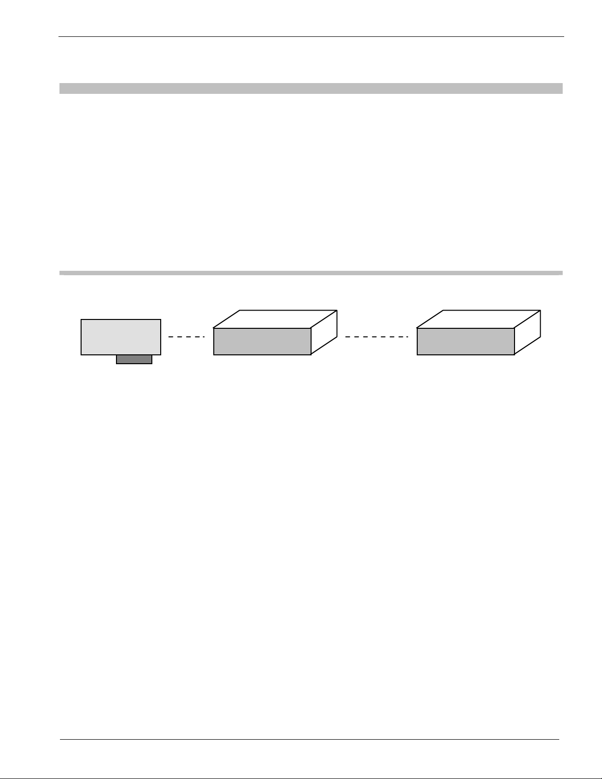
Controllers Each instruNet Network is controlled by a Network Controller board that installs
into a computer. A different controller board is used with each common bus
interface (e.g. PCI, PC-Card), yet they are all very similar internally. Each
Controller is an independent computer in itself that utilizes a powerful 32-bit
microprocessor and onboard RAM to control all aspects of data acquisition along
its network. One can install as many Controllers as desired, space permitting, since
each controller operates independently. Each network supports up to 32 Network
Devices. Each Device is a small box (e.g. 10cm x 12cm x 25cm) that is connected
in a daisy-chain configuration to form a chain of Devices. Each network can be up
to 300 meters long. All networks are anchored with an instruNet Terminator at the
far end, and an instruNet Controller at the near end. This makes instruNet a cost
effective method for designing large scale, high speed, multi-channel data
acquisition systems. The following table lists the instruNet Controllers described
in this manual.
Network
Device
Network
Device
1-1

Ch 1 Installation
Model Controller Bus Size Computer Required
200 PCI Controller PCI 7" x 4" Windows 95/98/Me/Nt/2k/Xp Computer
with PCI Rev ≥2.0 compliant, 32-bit, +5V
slot; or Macintosh OS >= 8 (must boot OS 9
if on OS >= 10.2 Mac) with PCI Slot.
230 PC-Card
Controller
PC-Card 2" x 3" Windows 95/98/Me/2k/Xp (not NT)
Computer or Macintosh OS >= 8 (must boot
OS 9 if on OS >= 10.2 Mac) PPC/G3/G4/>
Powerbook computer (i.e. Models 1400,
2400, 3400, 5300, >=G3). Requires Type II
PCMCIA compliant ≥ v2.1 (or ≥ PC-Card
95) PC-Card slot.
Table 1.1 instruNet Controllers described in this Manual
Network Network Devices typically provide voltage input channels, voltage output channels,
Devices digital inputs and digital outputs. The following Network Devices are described in
this manual:
Voltage Inputs Voltage Outputs
Model
# of
Channels
100 16ch w/
screw
terminal
access
Range
+/- 5V
+/-.6V
+/-80mV
+/-8mV
Absolute
Accuracy
+/-1500µV
+/-150µV
+/-45µV
+/-30µV
# of
Channels
8ch with
4mA/1KpF
Drive
Capability
Write
Accuracy
Read-back
Accuracy
Digital
I/O
+/- 40 mV +/- 3mV 8
Bidirectional
I/O Bits
100B Same as #iNet-100, yet with 16 additional BNC connectors for 16se voltage inputs.
100HC Same as #iNet-100, yet with voltage outputs that have 15mA/.01uF drive capability.
Table 1.2 instruNet Network Devices described in this Manual
instruNet instruNet includes software to interrogate, test, configure, and do I/O with all
Software network channels. This includes an application program called "instruNet World";
drivers; interfaces to C, and Visual BASIC. instruNet World and the instruNet
Driver can configure all I/O channels, store your settings, view digitized data in
real time, stream data to disk, and scroll through your waveform post-acquisition.
instruNet software runs on both a PC and a Macintosh OS >= 8 (must boot OS 9 if
on OS >= 10.2 Mac).
Free Updates Free software and manual updates are available on the web at:
www.instrunet.com
1-2

Ch 1 Installation
Computer Requirements
The following table summarizes the computer required to run instruNet:
Model Controller
200 PCI
Controller
230 PC-Card
Controller
230 PC-Card
Controller
Computer
Required
IBM PC or
Compatible
≥ 80486
IBM PC or
Compatible
≥ 80486
Macintosh
PPC/G3/G4/>
Powerbook
OS
Required
Windows
95/98/Me
Nt/2k/Xp
Windows
95/98/Me/2k/
Xp (not NT)
OS >= 8 (must
boot OS 9 if
on OS >= 10.2
Mac)
RAM
Required
HD
Required
≥ 4MB ≥ 6MB
free
≥ 4MB ≥ 6MB
free
≥ 4MB ≥ 6MB
free
PCI Slot, ≥6.8", Rev
≥2.0 compliant, 32-bit,
+5V
Type II PC-Card Slot
with ≥ v2.1 PCMCIA
compliant card services
Type II PC-Card Slot
with ≥ v2.1 PCMCIA
compliant card services
Table 1.3 Computer Requirements for instruNet Controllers
Slot
Required
Constructing Your Network
instruNet hardware is 100% plug and play for all computers. instruNet does not
use dip switches, DMA, low memory, interrupts, and I/O addresses. All you need
to do is plug the Controller board into your computer, connect your network
devices, slap a terminator onto the end of your network and run the instruNet
World software. The instruNet driver automatically determines the physical
locations of all installed Controllers and Network Devices.
Please keep in mind the following when designing and constructing your network:
1. Install as many controllers as desired
The number of available slots determines the number of controllers (i.e.
networks) that can be installed, and simultaneously run, on one computer. The
software numbers each controller in the order that they are found in the
computer ("netNum" ranges from 1 to # of Controllers). Each controller
manages it's own network of devices. In most cases, only one controller is
necessary. The advantage of multiple controllers is that each is its own realtime machine, and more controllers can do more things simultaneously.
2. Install up to 16 Devices on each Network
One can attach, in daisy-chain configuration, up to 16 Network Devices to each
instruNet Controller. Each Network Device has two DB-25 connectors, one for
network input (male), and another for network output (female). To connect a
chain of Network Devices, one must connect each input connector to each
output connector via a DB-25 Male/Female cable. The Controller is attached to
the first device in the chain, and an instruNet Terminator is attached to the far
1-3

Ch 1 Installation
end of the chain. Due to the male/female polarization, the network cannot be
installed incorrectly with instruNet Male-Female cables.
3. Each Controller includes Timer I/O Channels
Each Controller (except iNet-230 PC-Card) provides 10 Timer I/O channels.
Each channel can be programmed as a digital input, digital output (0V/4V TTL
compatible), clock output, or period measurement input.
4. Each Controller includes one Terminator
One instruNet Terminator must be installed at the end of each network chain.
This terminator mates with the output connector of the last device. instruNet
Controllers include an instruNet Terminator, therefore they do not need to be
purchased separately. Caution: Do not use a SCSI Terminator in place of an
instruNet Terminator -- they are different.
5. Each Network Device includes one cable
Each instruNet Network Device is shipped with one 10foot DB-25 Cable
Male/Female cable for purposes of configuring your network.
6. You can purchasing your own cables
If you want a specific cable length, you can purchase your own DB-25 male to
DB-25 female, shielded, wired point-to-point (i.e. pin X to pin X) cables. We
recommend 24 gauge wire for > 4 meters; however 28 gauge is fine with ≤4m.
Twisted pairs are recommend for >4 meters with the following wires twisted: 1
& 14, 2 & 15, 3 & 16, 4 & 17, 5 & 18, 6 & 19, 7 & 20, 8 & 21, 9 & 22, 10 &
23, 11 & 24, 12 & 25 (these are physically next to each other in the connector).
Also, it is recommended that the drain wire (which is attached to the shield) be
connected to the housing and pin #1 (GND) on both connectors. For more
information on cables, please refer to Application Note #22, Third Party
instruNet Cable Suppliers; and Application Note #39, Use Low Capacitance
Cable to Maximize your instruNet Network Speed.
A supplier of high quality twisted pair, low capacitance, double-shielded cable
without connectors is Belden, Inc. The Belden Cable Part #8112 Low
Capacitance RS-485/RS-232 cable is available in 100ft, 500ft, and 1000ft
lengths with 12.5 Pairs and a copper braided shield. This cable features 24
gage wire, 41pF/meter between pairs, 72pF/meter between a wire and the
shield, and 78ohms/killometer wire resistance
7. Minimum Base System
One Controller and one Network Device is all you need to purchase to digitize
waveforms, save them to disk, and view them.
8. Maximum Sample Rate
As the physical length of the network increases, the maximum aggregate data
acquisition sample rate decreases from 166Ks/sec maximum with a short
network (e.g. 5 meters) to 4.15Ks/second aggregate with a long network (e.g.
300 meters).
1-4

Ch 1 Installation
This maximum aggregate rate applies to a batch of input channels. For
example one instruNet network can support 4 voltage input channels at a
maximum rate of 41.5Ksamples/sec for each channel (i.e. 166Ks/sec
throughput). The same network would allow 8 channels of voltage input to be
acquired at 20.075Ks/sec per channel. The maximum aggregate rate can be
increased by installing additional instruNet networks and controllers. For
example, two controllers could support 332Ks/sec aggregate throughput if run
simultaneously.
When the instruNet powers up, it empirically tests (i.e. it test the cable
impedance) of the network to determine its maximum throughput rate (i.e.
4.15K/sec to 166Ks/sec). The maximum rate is decreased by: additional
network devices, longer aggregate network cable length, non-twisted pair
cables, and thinner cable wire (e.g. 28 gauge instead of 24 gauge).
For more information on sample rates, please refer to Application Note #58 and
#117 (URL's www.instrunet.com#58, www.instrunet.com#117).
9. Turn power OFF when cabling
Always turn the computer and powered Network Devices Off before adjusting
network cables.
10. Large networks require external power supplies
The instruNet network cable provides power from the computer to the external
Network Devices. As the number of devices increases (more current drawn),
and the cable lengths increases (more voltage drops), it becomes increasingly
necessary to add an external power supply for the Network Devices. We
recommend adding an external power supply if your cable is > 50 meters, or for
every 4 Network Devices after your 3rd Device. In other words, only add an
external power supply if you have more than 3 network devices, or if your
network is longer than 50 meters.
Software Installation
To install instruNet SOFTWARE on a Windows 95/98/Me/Nt/2k/Xp/>
Computer:
1) Before installing instruNet Software >= v2.0 (which includes iW+) from CD or
from Internet URL www.instrunet.com/d: Turn OFF anti-virus (AV) software,
Disable any Anti-Virus "Automatically Launch on Startup" options, Restart
your computer, login as ADMINISTRATOR if on Windows Nt/2k/Xp/>,
Check that AV software is Off, and Make sure that other application programs
are Off. AV must be OFF after Restart since Installer may Restart several
times. This is Crucial, especially with older AV software that conflicts w/
modern Windows XP installers.
1-5

Ch 1 Installation
2) Install instruNet software Before installing physical i2x0 Controller card by
inserting instruNet CD into your computer (which automatically runs
"Setup.exe"), or by downloading Installer from "www.instrunet.com/d" (which
downloads "instrunet_web_setup.cab", opens it via WinZip, and then runs the
"Setup.exe" inside). If it asks you if you want to install the .Net Framework,
say Yes if running under Windows >=98 and <= 2K (not 95, not XP); and you
want to run programs VB Instrument, VB Scope or Direct To Excel; and you
don't mind waiting another 2 to 30min for the installer to run. Installation
might take up to 1 hour, especially with older computers that require more files.
If you become concerned your computer has frozen, please check your hard
disk light -- if it is blinking, you are Ok. When the instruNet installation is
complete, an "instruNet World" Icon appears on your desktop and an alert
notifies you of the success. At this time, it is safe to turn ON anti-virus
software. For information on installing instruNet hardware & drivers, please
continue with the below instructions.
To enable instruNet World+ (iW+) SOFTWARE on a Windows
98/ME/Nt/2k/Xp/> Computer:
For information on how to enable instrunet World+ (iW+) software, please see the
"instruNet World+ Software License Installation" discussion at the end of this
chapter, or refer to your "instruNet World+ (iW+) License x For Serial # y" sheet,
included with iW+.
To install instruNet i200 PCI or i230 Pcmcia HARDWARE on a Windows
95/98/Me Computer:
1) Make sure you are on a Windows 95/98/Me computer, Install the instruNet
software, as noted above, Turn computer POWER off, Install the physical
instruNet PCI or PCMCIA card, Attach the instruNet network devices, Attach
the instruNet terminator, Tighten the thumbscrews, and Turn the computer on.
2 It may ask you for a PCI or PCMCIA Card Driver on boot-up. Navigate via the
Browse/Other Locations button to the .inf/.vxd files on your computer. For
PCI, go to "Program Files \ instruNet \ internal \ PCI or PCMCIA Win95 Driver
\". Press Next to move through the installation process. It might say "Please
insert disk labeled 'Program files \ instruNet \ internal \ Pcmcia or Pci Win95
Driver \' directory". At this point, you must navigate to "Progra~1 \ instru~1 \
internal \ Pcmcia~1 \ iNt95Pcm.vxd" for Pcmcia or "Progra~1 \ instru~1 \
internal \ PciWin~1 \ iNet95.vxd" for PCI. You might need to type
"iNt95Pcm.vxd" for Pcmcia or "iNet95.vxd" for PCI into the file name field,
while "Progra~1 \ instru~1 \ internal \ Pcmcia~1 or PciWin~1 \" is selected in
the Directory area. When done, the card should be listed under "Data
Acquisition Cards" in the System "Device Manager". Reboot your computer
and then proceed to "To Verify Your System...", below.
To install instruNet i200 PCI or i230 Pcmcia HARDWARE on a Windows
Nt/2k/Xp/> Computer:
1-6

Ch 1 Installation
Make sure you are on a Windows Nt/2k/Xp computer (or later), Install the
instruNet software, as noted above, Turn computer POWER off, Install the physical
instruNet PCI or PCMCIA card, Attach the instruNet network devices, Attach the
instruNet terminator, Tighten the thumbscrews, and Turn the computer on. If it
asks for a .sys/.inf driver, navigate to "\ Program Files \ instruNet \ Internal \ PCI or
PCMCIA Win 2k-Xp Driver \" for PCI "inet.sys, inetpci.inf" or PCMCIA
"inetpcm.sys, inetpcm.inf". The i230 does not run under Win NT. Proceed to "To
Verify Your System...", below.
To install instruNet i200 PCI or i230 Pcmcia HARDWARE/SOFTWARE on a
Macintosh computer:
1) Make sure you are on an OS >= 8 Macintosh (must boot OS 9 if on OS >= 10.2).
The i200 requires a PowerPC/G3/G4/> Mac w/ 1 free PCI slot. The i230 requires a
Powerbook 1400/5300/2400/3400/G3/G4/> Mac with at least one free Type II
pcmcia slot.
2) Copy the Macintosh instruNet software to your computer (from the included
instruNet CD in the "Macintosh" directory, or from www.instruNet.com/d). If
the files are compressed (i.e. the file has an ".sea" or ".sit" suffix), uncompress
them with Stuffit Expander >= 5.1.13 from Aladdin Systems. Copy into your
Extensions folder (inside your System folder) "instruNet Driver (ppc)". If
working with SuperScope II, use the version of "instruNet Driver (ppc)"
included with instruNet.
3) Turn computer POWER off, install the instruNet PCI/Pcmcia card, attach
instruNet network devices, attach instruNet terminator, tighten thumbscrews,
turn cpu on, and proceed to "To Verify Your System...", below. On a
Powerbook 1400/5300 with an i230, it might say "please install driver". Please
ignore this alert, since the driver is inside instruNet World.
To Quickly Verify That Your System Is Working Properly:
To test instruNet, run "Start > Programs > instruNet > instruNet World" if on
Windows or run "instruNet World Mac" if on Macintosh, press the TEST tab at the
bottom of the window, press the SEARCH button and make sure your hardware is
listed (e.g. i200 card, i100 box). If the list is not correct, please see Note #69,
"Troubleshooting" (www.instrunet.com\trouble). Otherwise, if the list is correct,
please see the 1 page Note #209 "Getting Started Quickly with Windows"
(www.instrunet.com\start) document and then proceed to the instruNet User's
Manual Ch 2.
For details on verifying proper operation, please see the "To Verify …" discussion
later in this chapter.
To copy instruNet software From www.instrunet.com To non-networked
computers:
Surf to "www.instrunet.com/s" via Internet Explorer. Drag file
"instrunet_web_setup.cab" from your browser window to your hard disk -- to
download this file to your computer. Open this .cab file with decompression software
1-7
Ch 1 Installation
such as WinZip (a popular program for opening .zip files) and copy it's contents (i.e. a
"setup.exe" file) to the computer(s) on which you want to install instruNet Software
(i.e. via burning a CD, or via a local area network), and Install per the above
instructions.
Hardware Installation
To install an instruNet network, please:
1. Read the previous "Constructing your Network" discussion. Before installing
hardware, please install software per the pervious instructions.
2. Turn OFF your computer.
3. Turn OFF all powered devices connected to your network.
4. Touch bare metal on your computer to discharge personal static electricity.
5. Remove the cover from your computer to gain access to the card slots, as
needed.
6. Remove the small I/O fence cover from the back of your computer, as needed.
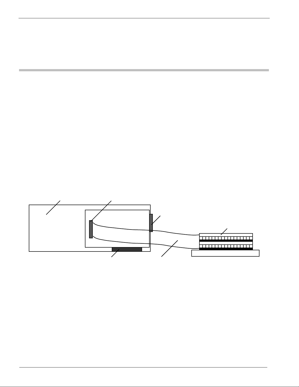
7. If you require access to an available Controller Digital/Timer I/O Channel, run
a 34-wire ribbon cable from the Controller's 34pin header connector, out of the
computer, any way you can (e.g. through another slot opening), to the breakout
of your choice (e.g. a screw terminal block), as illustrated below:
Digital I/O & Clock
Computer
I/O Connector
ioNet
Controller
Computer Bus (PCI, Nubus)
Figure 1.4, Installing an instruNet Controller into a Computer
8. Install the instruNet controller(s) into the computer's expansion slot(s). If working
with a PCI Card, make sure the Controller connector is well seated and inspect this
connection with a strong light to make sure the printed circuit board fingers are
aligned with their mating connector pins.
9. Bolt the board metal I/O fence to the computer, as needed (some computers do
this). Please skip this step if tightening this bolt causes the card to not seat
well in its connector.
10. Put the cover back onto the computer, as needed.
11. Attach the external instruNet Network Devices in a daisy chain configuration,
as illustrated below.
DB-25 connector (male)
34-wire ribbon cable
34-wire screw terminal
1-8

Ch 1 Installation
DB-25 connector (male)
instruNet Terminator
Computer
Network
Device #2
instruNet
Network
Device #1
Controller
DB-25 Cable DB-25 connector (female)
Figure 1.5, instruNet Network
12. Tighten all DB-25 thumbscrews until lightly snug.
13. Install an instruNet Terminator on the end of each network.
14. It is recommended that the user attach the instruNet instrumentation ground
(i.e. instruNet box and instruNet GND screw terminals) directly to Earth
ground with a 16gauge wire from the left-most GND screw on the instruNet
box, to the closest Earth ground (e.g. screw next to power socket). This will
reduce the chance of RFI coupling into the instruNet ground, and is required
if the user wants to meet EC and FCC RFI guidelines.
15. If working with an iNet-230 PC-Card, attach an external power supply (e.g.
iNet-311.x, 312.x, 322.x) to the PC-Card 5pin DIN connector. This supplies
power to the external network devices (i.e. not the PC-Card itself).
16. Turn the computer power ON and then Turn ON all powered devices attached
to the instruNet network.
Verifying That Your System Is Working Properly
Verify that your hardware and software is working in 5 easy steps:
1. Run the "
on Macintosh, and "instruNet World Win32.exe" on a Microsoft Windows
computer), in the
instruNet directory. A
window will open,
similar to what is
pictured to the right. If
necessary, you might
need to click on the
Network tab at the
bottom of the window
to select the Network
page. If this window
opens, then you know
your instruNet driver
1-9
instruNet World" application program ("instruNet World Mac"

Ch 1 Installation
file is installed and working correctly. The list of channels shown in the
window's table will vary, depending on what instruNet hardware is connected.
If the instruNet window does not appear, then check the Software Installation
section at the beginning of this chapter to make sure that the software has been
installed correctly. If it appears that the software is installed correctly but not
functioning properly then see Application Note #69 Troubleshooting
(www.instrunet.com\trouble) and instruNet User's Manual Appendix I Trouble
Shooting.
2. Press the Test tab at the bottom of the window to select the Test page, and then
press the Search button at the top of the window. A report will print that lists
the controllers and network devices that are currently installed on your
computer. For example, the report below shows one Controller, and one Model
100 Network Device.
instruNet HARDWARE SEARCH RESULTS: Date & Time: 10/2/1997, 12:12:41
Net Dev Mod Device
--------------------------------------- 0 0 0 Mac OS Ver 7.5.3
0 0 1 instruNet Driver Version 1.24
0 0 1 instruNet World+ license Not Installed (costs extra)
1 0 1 PCI Controller #iNet-200 (slot #13, 4000KBD, 6us, 94%)
1 1 1 Device #iNet-100 (SN37532, Cal 9/28/97, Rev4, 30.99C, ...
If this does not match what you believe is installed on your network, then check
your hardware installation (cables, power, etc). Also, it is possible that the
instruNet Driver is older than the devices on your network, which means you
need the latest driver that recognizes these new devices. The instruNet Driver
is always listed as the 1st installed item.
3. Press the Test button at the top of the window to test your controllers and
devices, and to report any problems if found. The duration of the test can vary
from 1 to 120 seconds depending on the size of the networks, and the speed of
the computer. If no problems are found, a report similar to the one below is
printed in the window:
INSTRUNET QUICK TEST RESULTS:
Date & Time: 10/12/1995, 12:53:23
We ran 0.510029 million tests and did NOT hit 1 error.
4. Press the Big Test
button to run an
exhaustive test. An
alert similar to the one
on the right will appear
to communicate that the
computer will test all instruNet hardware until there is an error, or until you
press the mouse button down. It will test your network(s) all night long if you
let it. Press OK to begin the Big Test. Wait 20 seconds or longer. If an error
occurs while testing, an alert will appear and the error message will also be
printed in the window. Refer to Appendix II instruNet Error Codes for more
information on error codes, and Appendix I Trouble Shooting for tips on de-
1-10

Ch 1 Installation
bugging if necessary. If no error alerts appear, and you want to stop the test,
press the mouse button down and hold it down until the an alert appears
announcing the end of the test. Click OK to exit this alert. The test results are
printed in the window, in a format similar to what is shown below:
We ran 2.170272 million tests and did NOT hit 1 error.
Big Test is identical to Test, except it runs for a longer period of time and is
useful at finding intermittent problems that only occur once every minute, hour,
or day. Big Test can be run overnight for extensive testing of all hardware.
5. You are done! Your instruNet hardware and software is installed correctly and
running beautifully. Please see the 1 page Note #209 "Getting Started Quickly
with Windows" document (www.instrunet.com\start) and then proceed to the
instruNet User's Manual Chapter 2, Tutorial to learn more.
instruNet World+ Software License Installation
Overview instruNet World (not +) software is available free of charge and included on the
instruNet CD with each i2x0 controller card (and at "www.instrunet.com/d"). The
"PLUS" version (referred to as "instruNet World+" or "iW+"), with more features,
is available at an additional charge under the following product numbers:
• #iNet-350-SerialNumberOfController, instruNet World+ for pre-existing i2x0
controller card. One must specify the serial number of that controller on their
Purchase Order, since license codes are keyed to controller serial numbers.
• #iNet-200P, instruNet PCI card and instruNet World+
• #iNet-230P, instruNet PCMCIA card and instruNet World+
Since the PLUS software is included inside the NOT plus software, one only needs
to register the iW+ license code, described below, to enable the PLUS software
after installing the NOT plus software (i.e. after running the instruNet CD).
Licenses are issued for each individual controller cards and are keyed to the
controller's serial number. Subsequently, the PLUS features are only enabled in the
following cases:
• A valid PLUS license code is installed, yet no controller card is installed.
• A valid PLUS license code is installed, along with it's corresponding controller
card.
• instruNet software is running in Demo mode and simulating a controller card.
iW+ Installation
To install an iW+ license on your computer and enable its powerful features on
Windows 98/Me/Nt/2k/Xp/> computers (iW+ is not supported on Macintosh):
1-11

Ch 1 Installation
1. In order to proceed, you must have purchased instruNet World+ (iW+) software
and have received an iW+ license code for your controller card. To learn more
about PLUS, please select "instruNet World+ Manual" in the "Help" menu
within instruNet World, or see Internet URL www.instrunet.com/plus.
2. Install instruNet software Version >= 2.0 onto your computer via the instruNet
CD, or from web URL "www.instrunet.com/d".
3. Launch the instruNet World software by double-clicking on its icon, or by
selecting START > Programs > instruNet > instruNet World.exe.
4. Select "Install instruNet World Script License…" in the Script menu.
5. Enter your license code (i.e. in the zz-ssssss-yyyyy format) into the license field
(note that "0" refers to number 0).
6. Press Ok, and a confirmation alert will appear. To view the status of your
license, press the Test tab at the bottom of the window and then press the
Search button. From this point forward, whenever you run instruNet World on
this computer (i.e. START > Programs > instruNet > instruNet World.exe), you
will be running iW+. Since the license code is stored in a file within the
System directory, installing newer versions of instruNet software will not
require repeating this procedure. To learn more about PLUS, please select
"instruNet World+ Manual" in the "Help" menu within instruNet World, or see
Internet URL www.instrunet.com/plus.
1-12

Ch 2 instruNet Tutorial
Chapter 2, instruNet Tutorial
This chapter is a step-by-step tutorial that shows the user how to navigate within
the world of instruNet. Controlling instruNet hardware can be done manually
though the free instruNet World application program, or through the programming
languages Visual Basic and C. This chapter deals exclusively with the easy-to-use
application program instruNet World application program while Chapter 4 covers
programming languages. instruNet World software allows you to set up and probe
your network, record waveforms, save them to disk, load them from disk, and view
them post acquisition.
This manual focuses on the buttons at the top of the instruNet World pages, yet
these functions can also be accessed in the menubar. For documentation on the
menubar and on instruNet World PLUS "iW+" (a version of instruNet World with
more features), please select "instruNet World+ Manual" in the "Help" menu
within instruNet World, or see Internet URL www.instrunet.com/plus.
Record Waveforms in 7 Easy Steps
This section explains how to record waveforms in several easy steps.
1. Install your hardware and software per instructions in Chapter 1
If your instruNet World hardware and software is not installed, please install
it now, as described in Chapter 1.
2. Run the instruNet World application program.
Locate the instruNet world application program within the instruNet folder on
your hard disk and then:
Windows: Double-click on "instruNet World Win32.exe",
or run "Start > Programs > instruNet > instruNet World".
Macintosh: Double-click on the "
3. Select the Network Page.
instruNet World offers several Pages: Record, Network, and Test. Click on
the Network tab at the bottom of the window to select the Network page. The
Network tab will inverse black to indicate the Network page is selected.
instruNet World Mac" icon.
2-1
Ch 2 instruNet Tutorial
Click here to select the Network Page
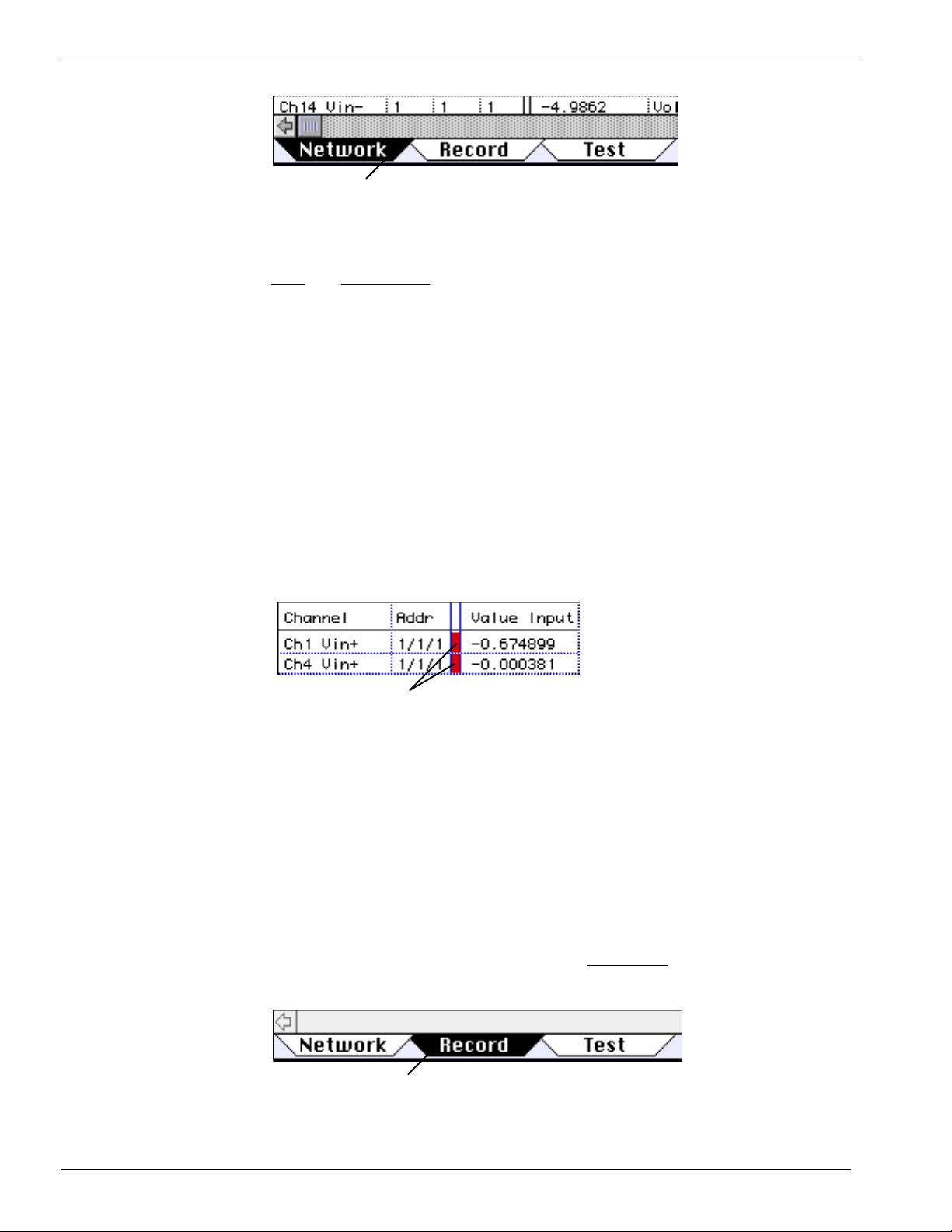
4. Enable a Channel for digitizing.
A channel is enabled for digitizing by clicking on the small cell between the
addr and Value Input columns within the Network page, as illustrated below.
Once enabled, the channel will be digitized when the user presses the Start
button on the Record page. To disable a channel, one must click the digitize
on/off cell again. This digitize on/off cell is black or red when On, and white
when Off. Any number of channels can be selected for digitizing.
Please enable two voltage input channels (e.g. "Ch1 Vin+" and "Ch4 Vin+"
on the Model 100) for digitizing, as illustrated below. Voltage input channels
are typically labeled ChX Vin+ or ChX Vin-. These work identically when
doing single-ended voltage measurement (i.e. read a voltage between an input
terminal and ground), and are used as a pair when doing differential voltage
measurement (i.e. reading a voltage between 2 input channels). If instruNet
voltage input hardware is not installed, you will not be able to digitize. Also,
note that the contents of the Network page may vary depending on what is
installed on your computer.
To Enable/Disable a Channel for digitizing
5. Attach a signal source.
If possible, attach a signal source to at least one channel's hardware input
terminal. For example, one might attach a Function Generator output to
the instruNet "Ch1 Vin+" input terminal, and the Function Generator's
ground to the instruNet "AGND" terminal. It is not necessary to connect
a signal source to do the tutorial, however, the displayed waveforms are
more interesting if a signal is applied; otherwise, you get a flat line at
0Volts.
6. Select the Record Page.
Select the Record page by clicking on the Record tab at the base of the
window, as illustrated below.
Click here to select Record Page
2-2
Ch 2 instruNet Tutorial
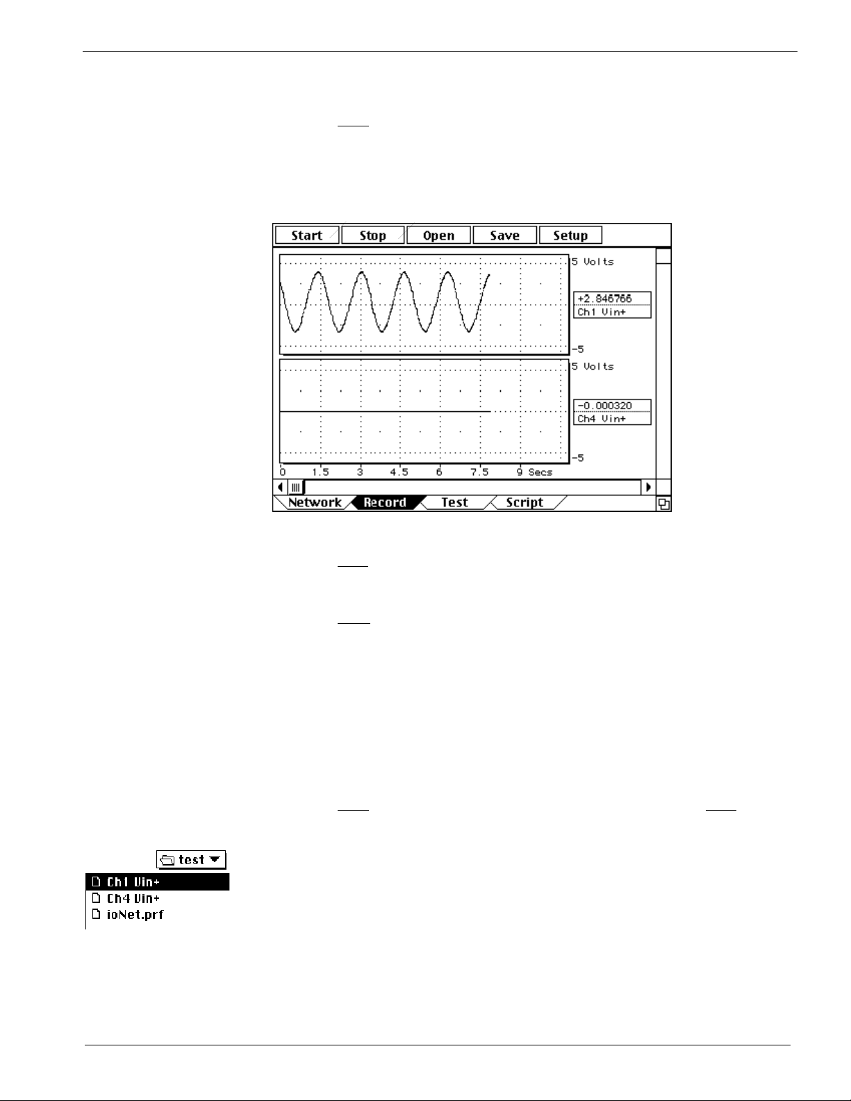
7. Tell instruNet to start digitizing.
Click the Start button at the top of the window to tell instruNet to record and
display channels that have been enabled for digitizing (e.g. "Ch1 Vin+").
You should see your waveforms move across the screen as they are digitized
in real-time, as illustrated below.
Click Start to start recording, Stop to stop recording
8. Tell instruNet to stop digitizing
Click the Stop button to stop the digitizing process.
9. Save your waveforms to disk
Click the Save button to save your waveforms to disk. When the save
dialog appears, type a name and choose a convenient location to save the
data. Saving does not specify a file name, but rather a folder name in
which all acquired waveforms and a preferences file are saved. For
example, if you digitized 2 waves and then clicked Save, 3 files would be
stored in your: one named "instruNet.prf" that contains the Field settings,
and two files that have the same name as the two channels, that contain
the wave data.
10. Record again
Click the Start button to start recording again, and then click the Stop
button after a few moments.
11. Load your saved waves from disk
Click the Open button to load in the previously saved waves from disk. A
File open dialog will appear, and it is here that you must select one of your
previously saved files (e.g. "instruNet.prf", "Ch1 Vin+" or "Ch4 Vin+").
After your waves are loaded in, they should appear in their displays .
2-3

Ch 2 instruNet Tutorial
Digitizing Directly To Excel
If you want to learn how to digitize in instruNet World, and then save a text file to
be loaded by a spreadsheet program, post-acquisition, please refer to Appendix III.
If you want to digitize into a spreadsheet,
consider the Direct To Excel program, described here. Note that Direct To Excel
requires that an iW+ license be installed on your computer.
• In order to run Direct To Excel,
All of the following must be installed on your
computer. If this is not the case, please proceed to the next section.
o Windows Excel version >= 8.0 (i.e. Microsoft Office >= 97)
o Windows >= 98 (not Windows 95, not Macintosh)
o iW+ license (see www.instrunet.com/plus for details)
o Windows .Net Framework (which is included with the instruNet
software, and is included automatically on Windows >= XP computers)
o instruNet software >= 2.0 (7/1/2003), available at www.instrunet.com/d
If you are not sure these requirements have been satisfied, try running the Direct
To Excel program, as described below, and if it runs ok, then you are probably
ok.
• Exit instruNet World and select under the Windows START menu: Programs /
instruNet / Application Software / Direct To Excel / Direct To Excel.exe. This
will run a program (shown below) written in Visual Basic; the source code of
which is currently installed on your hard disk. You are welcome to modify it.
while data is being acquired, please
2-4
• Press the Channels button, select 2 channels for digitizing (i.e. click in small
rectangle after channel address, it will turn red), and close the instruNet Network
window.
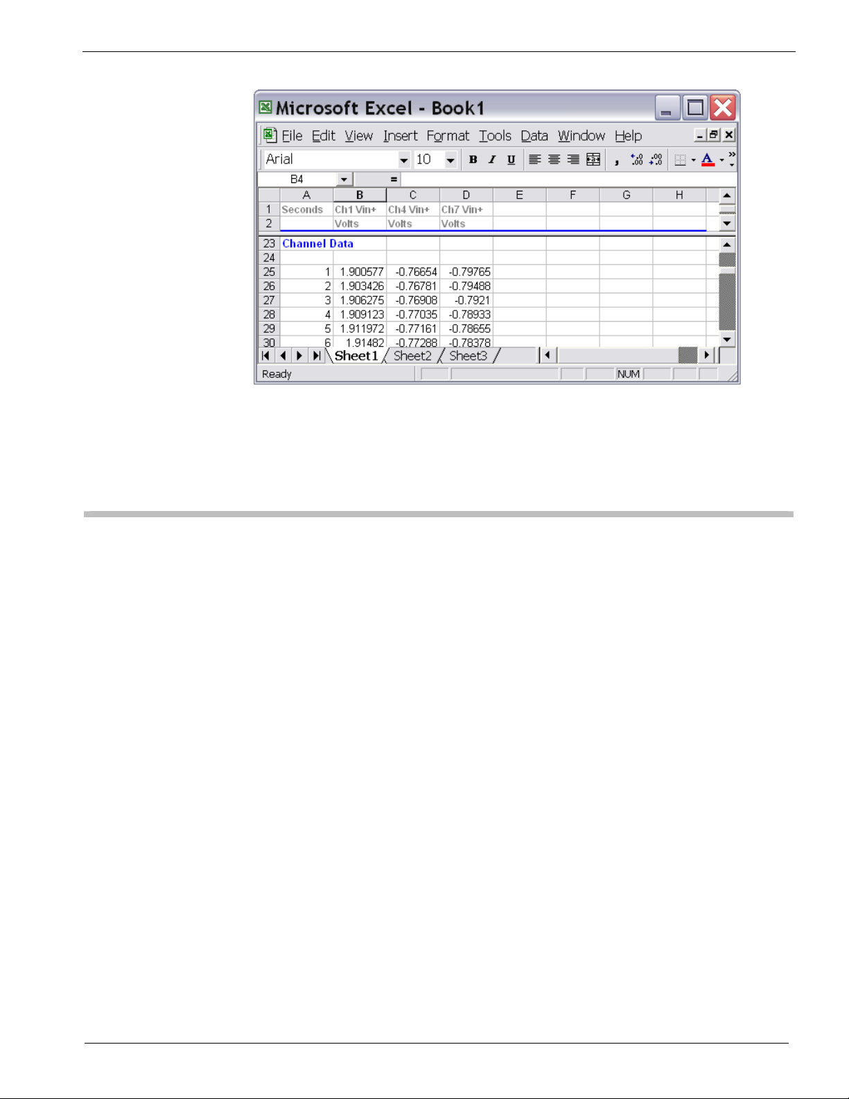
• Press the Start button and watch a new spreadsheet window appear and fill with
instruNet data, as shown below. When finished, you can save or delete the
Excel spreadsheet file.
Ch 2 instruNet Tutorial
• To learn more, please press the Help button.
• Close the Direct To Excel program by clicking in the upper right corner.
Working with VB Instrument
• We will now run a Windows program called "VB Instrument" that implements a
strip chart/oscilloscope recorder for 1 to 16 channels. It is similar to instruNet
World, yet is written in Visual Basic and the source code is installed on your
computer. You are welcome to modify it. If you are on a Macintosh, please
proceed to the next section.
• Exit any currently running instruNet software and select under the Windows
START menu: Programs / instruNet / Application Software / VB Applications /
VB Instrument.exe.
• Press the Channels button, select 4 channels for digitizing (i.e. click in small
rectangle after channel address, it will turn red), and close the instruNet Network
window.
• Press the Start button and watch the data appear in the window, as shown below.
2-5

Ch 2 instruNet Tutorial
• To learn more, please press the Help button.
• Close the VB Instrument program by clicking in the upper right corner.
Working with VB Scope
• We will now run a similar Windows program (written in Visual Basic, source
code included) called "VB Scope". It implements a 2 channel strip chart
recorder / oscilloscope, XY Record, and Spectrum Analyzer. If you are on a
Macintosh, please proceed to the next section.
• Exit any currently running instruNet software and select under the Windows
START menu: Programs / instruNet / Application Software / VB Applications /
VB Scope.exe.
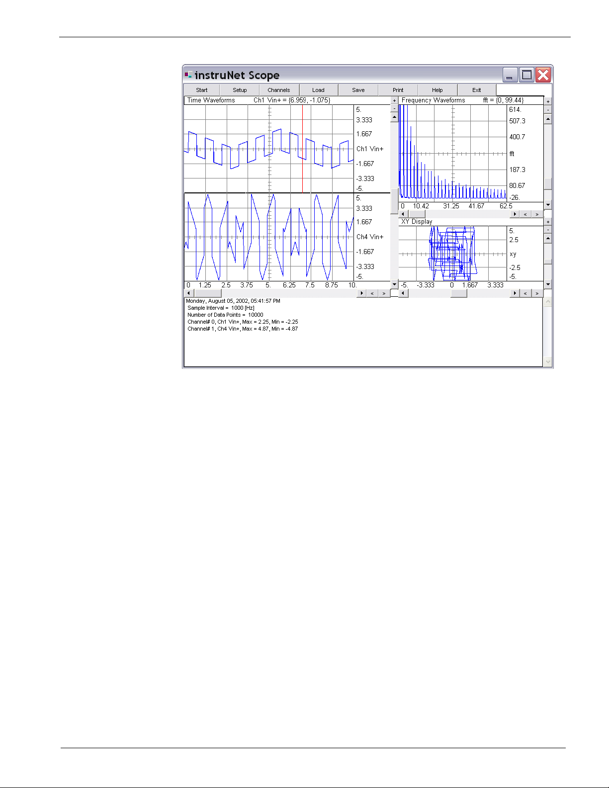
• Press the Start button and watch the data appear in the window, as shown below.
Ch1 and Ch2 timewaves are shown in the left-most display, the frequency
spectrum of Ch1 is shown in the upper-right display, and an XY plot of Ch1 and
Ch4 are shown in the lower-right display.,
2-6
Ch 2 instruNet Tutorial
• To learn more, please press the Help button.
• Close the VB Scope program by clicking in the upper right corner.
2-7
Ch 2 instruNet Tutorial
Digitizing Analog Signals into the Computer
The Setup button at the top of the Record page opens a dialog box that effects
the manner in which waves are recorded.
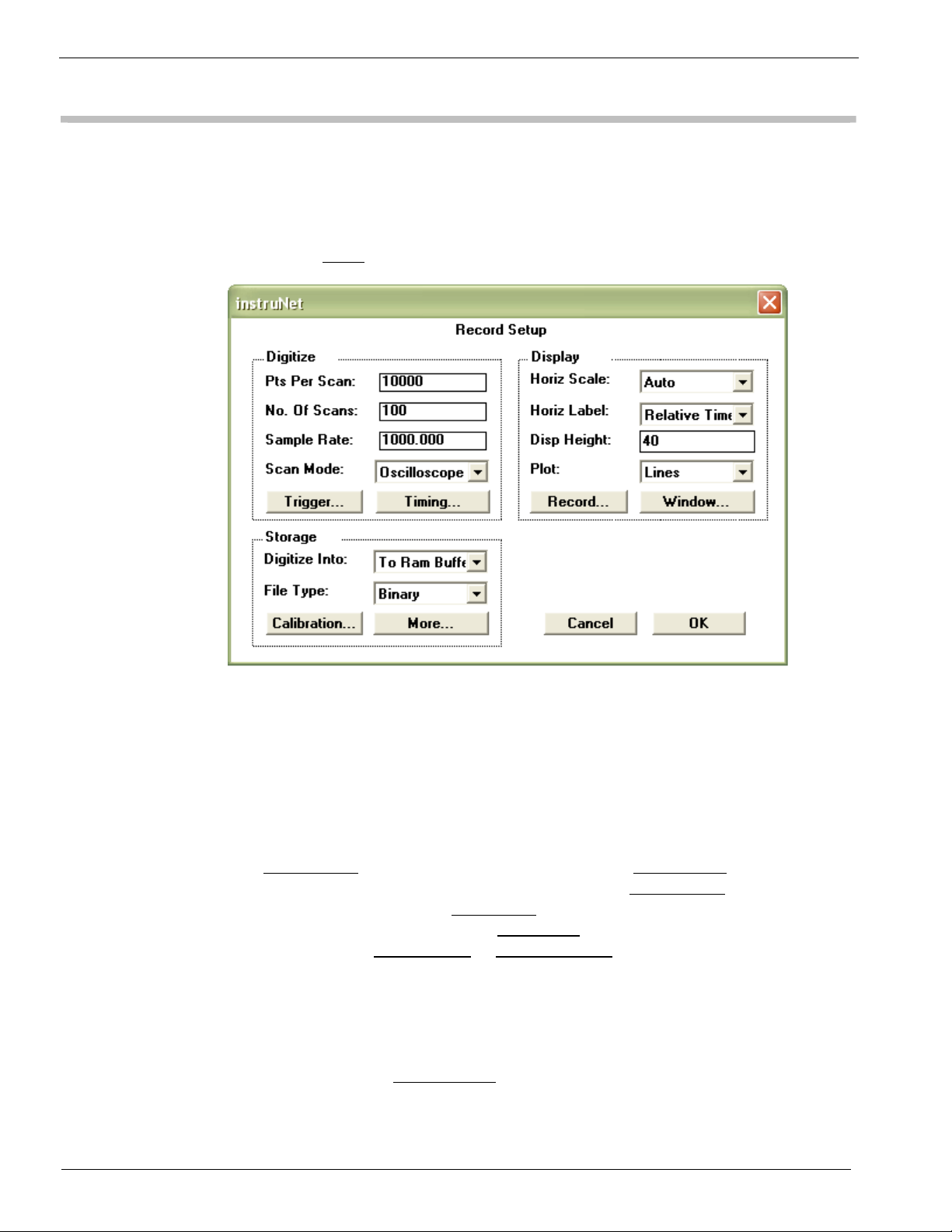
• Click the Setup button to open the Setup dialog, as illustrated in Figure 2.1.
Figure 2.1 The Record Setup Dialog
The Setup dialog is used to set the base sample rate, the number of points to be
acquired per Scan, the number of Scans to be acquired and the recording mode (i.e.
oscilloscope or strip chart recorder). All instruNet Networks are set up with one
base sample rate (i.e. number of points digitized per second) and individual
channels can have sample rates less than or equal to the base sample rate. This
allows, in effect, each channel to have its own sample rate.
The Sample Rate
the amount of data to be collected in each Scan. The No. of Scans
of Scans to be acquired. The Scan Mode
Oscilloscope, and Oscillo Queued. Strip Chart
recorder mode and Oscilloscope
mode. Refer to the
field sets the base sample rate. The Pts Per Scan field determines
sets the number
popup has three choices: Strip Chart,
is selected for continuous strip chart
or Oscillo Queued are selected for oscilloscope
Oscilloscope or Strip Chart section of Chapter 5 for a full
description of these modes.
instruNet Networks are self-configuring and on startup determine the maximum
rate at which data can be transferred. This rate is displayed after pressing the
Timing button, in the Network BPS
field, in units of bits per second. 4 million bits
per seconds is the fastest, and 100Kbps is the slowest. This rate slows down with
networks that have many Devices and long network cables (i.e. >100ft).
2-8
Ch 2 instruNet Tutorial
• Select Oscilloscope in the Scan Mode popup and set the Pts Per Scan field to
100. 100 points at 1000s/sec will take .1 seconds to acquire. Leave the rest of
the Dialog in its default settings, and click OK to return to the Record Page.
• Click the Start button to begin digitizing.
Notice how 0.1 second long waveforms continuously appear on the screen, in a
manner similar to an Oscilloscope. Before, we were in Strip Chart mode where
these segments were continuous with respect to each other. We are now in
Oscilloscope mode. To learn much more about digitizing, please refer to the
Record page discussion in
Chapter 5, instruNet World Reference.
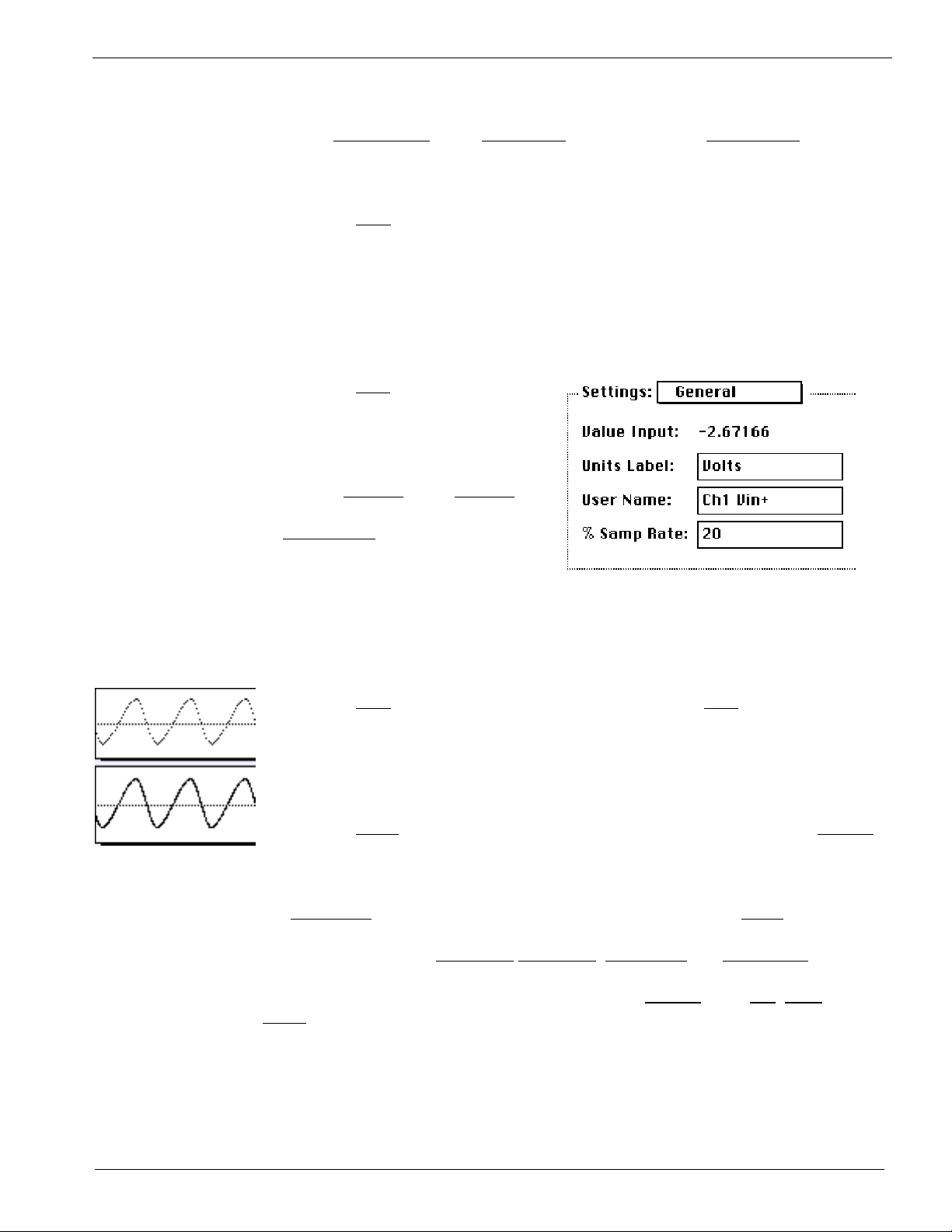
• Click the Stop button to stop
digitizing, and then click on the
top display's channel name label
at the right edge of the display.
The Display dialog will open.
Choose General
in the Settings
popup. Enter the value 20 in the
% samp rate
the right and press OK.
field as shown to
This will cause the top channel to be digitized at 20% of the master sample rate, or
200s/sec. The channel in the lower displays will continue to run at the master
sample rate of 1000s/sec.
• Click the Start button to begin digitizing, and then click Stop after a few
moments.
Notice how the wave in the top display contains fewer points, due to its
reduced sample rate, as illustrated to the left.
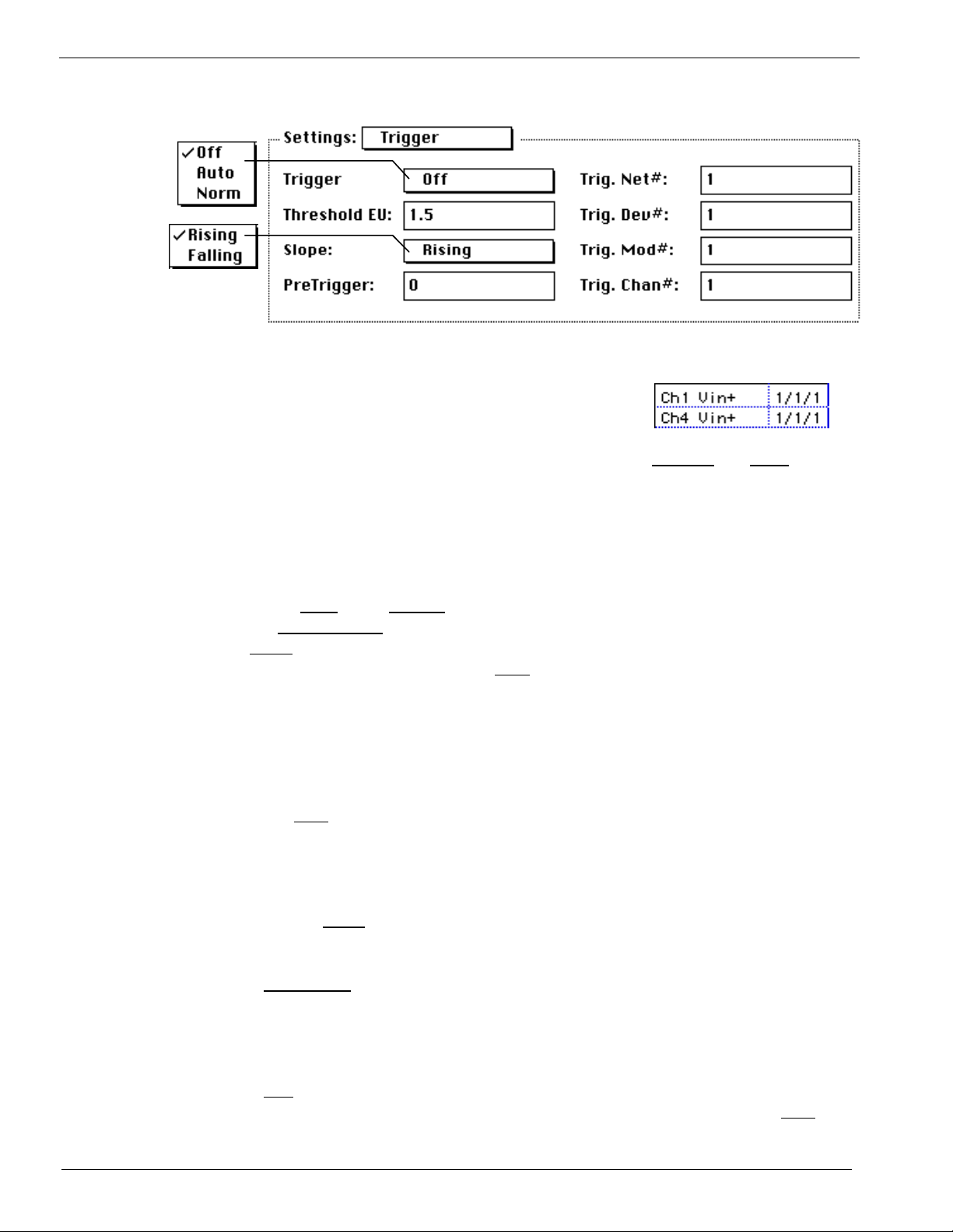
• Click the Setup button at the top of the Record page, and then click the Trigger
button to open the Trigger dialog, as shown in Figure 2.2.
Trigger Modes instruNet World allows triggering from any channel on either a low-to-high or
high-to-low transition through a threshold value. The threshold is specified in
the Thresh EU
field, and the trigger direction is specified in the Slope field (i.e.
low-to-high, or high-to-low). The channel to trigger from is specified by its
network address in the Trig Net#,
Trig Dev#, Trig Mod# and Trig Chan# fields.
Three trigger types are allowed, as specified in the Trigger
Norm
. If Off is selected, data acquisition begins as soon as the Start button is
field: Off, Auto and
pressed in the Record Page. If Auto is selected, data acquisition begins after
the trigger criteria is met, but if the trigger condition is not met within a second
or so, the recording begins anyway. If Norm is selected, instruNet waits until
the trigger condition is met, indefinitely of necessary.
2-9
Ch 2 instruNet Tutorial
Fig 2.2 The Trigger Dialog
• Enter the address of a channel to trigger from into
the Trig Net#, Trig Dev#, Trig Mod# and Trig
Chan# fields. If you are not sure of a channel's
address, go back to the Network Page and look at the Channel
and Addr column
for the channel you want to trigger from. The address for the two channels
shown in the above figure would be {1,1,1,1} and {1,1,1,4}. For example, if
you wanted to trigger from channel Ch4 Vin+, you would enter the following
values: 1 into Trig Net #, 1 into Trig Dev#, 1 into Trig Mod#, and 4 into Trig
Chan#.
• Select Auto in the Trigger popup, type a reasonable threshold voltage into
the Threshold EU
Slope
popup. Click OK to exit the Trigger Dialog, click OK to exit the
Setup Dialog and then click the Start
field (e.g. 1V) and then select Rising or Falling in the
button to begin recording.
The waveforms should appear on the screen, with the beginning of each Scan
synchronized to the trigger event. If the signal applied to the trigger channel
does not periodically cross the threshold voltage, Auto trigger will digitize
anyway every second or so.
• Press Stop when you are done acquiring.
To learn more about Triggering, please refer to the Record page discussion in
Chapter 5.
• Click the Setup button at the top of the Record page to open the Record
Setup dialog, as shown in Figure 2.1.
Display The Horiz Scale field sets the display horizontal scale in seconds-per-division. If
Options set to Auto, instruNet picks a horizontal scale that is appropriate based on the
sample rate and number of data points being acquired. This popup is also provided
at the lower right of the Record page when iW+ is installed.
The Plot
pixel for each data point, or connect these data points with lines), and the Grid
popup is used to set the drawing mode to plot Dots or Lines (i.e. light one
2-10
Ch 2 instruNet Tutorial
popup (accessed by pressing the Record button in Setup dialog) selects whether or
not to overlay a grid on each display.
Viewing The Disp Height field sets the minimum height of each display in the
Many Channels Record page, in pixels. If the number of waveforms being digitized is
greater than the available space on the screen, only a subset are
displayed, and the vertical scrollbar selects that set. For example, if the
Record page is 1000 pixels high, the Disp Height field is 100, and one
is digitizing 512 channels (the maximum amount); only 20 would be shown at one
time, and the vertical scrollbar would select that set of 20. In another example, if
the window was 640 pixels high, one was digitizing 32 channels, and one wanted to
see all channels at once; one would need to set the Disp Height field to 20 (i.e. 20
pixels * 32 channels = 640pixels).
Another technique is to hide individual displays by setting the Display View field
to Hide for each channel that you do not want a Display in the Record page. One
does this by opening the channel options dialog for each channel you want to hide,
select the Display setting, and then set the Display View field to Hide. If you want
to view channels numerically, then please consider Panel Meters, which are only
available in iW+ (described at www.instrunet.com/plus).
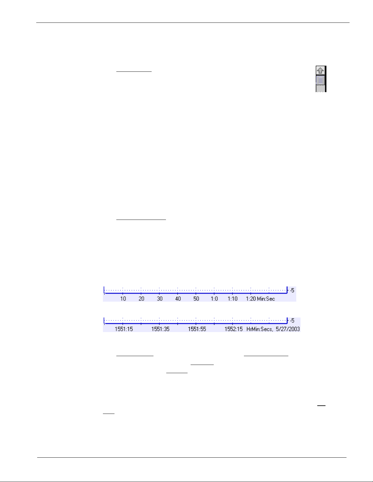
Time Of Day or The Horizontal Label field allows one to show either Relative time or
Relative Time Time of Day in the Record page horizontal timescale, as illustrated below.
Relative time shows the number of seconds since starting the digitization at 0
seconds. Time of Day shows the time of day, as known by the computer's clock.
For example, if you start digitizing at 1:05 am on Feb 1, 2003, it will show "0117,
2/1/03" 12 minutes later. Post-Acquisition, one can change this field to view the
data with either timescale format. Displaying Time of Day requires instruNet
World PLUS (iW+).
Time Relative to start of digitization, left edge corresponds to 0 secs
Time of Day, e.g. first grid corresponds to May 27, 2003, 3:51pm + 15 seconds
Digitize Into The Digitize Into popup has 2 primary settings: To Ram Buffer, which saves
Ram or File digitized data into RAM; and To File, which digitizes data directly to disk. If
Digitize Into is set to To File
, instruNet automatically prompts the user for a
folder name every time a recording session is initiated with the Start button.
The waveforms are then saved to this folder while they are recorded. One can
then scroll through these long disk-based waveforms (e.g. 20M points per
channel) via the horizontal scrollbar. Any waves saved to disk using the To
File option can be opened and scrolled through with the Record Page's Open
button.
2-11

Ch 2 instruNet Tutorial
The File Type
field determines the file format for the saved data, and is set to
one of Binary, Binary Merge, Text, or Text Merge. For a detailed description
of each format, please see File Type Application Notes.
• Select Lines in the Plot popup, select Off in the Grid popup, select "Strip Chart"
in the Scan Mode
popup and, set the Pts per Scan field to 10000 to set the buffer
size of an intermediate RAM buffer that holds data before it is sent to disk
(10000 points at 1Ks/sec is a comfortable size). Set the Digitize Into
"To File", and select 0.5 secs/div in the Horiz Scale
dialog. Click Start
to begin recording. When the File save dialog appears, type
popup. Click OK to exit the
popup to
a folder name and select a location for the waveforms that are about to be
"spooled" to disk.
• After a minute or so, press the Stop button to stop digitizing. Scroll through
your waveforms via the horizontal scrollbar. Notice that the computer goes to
your hard disk periodically to automatically load in information from disk.
RAM-Based It is recommended that one Digitize Into RAM if your RAM is large enough.
Digitizing RAM based digitizing is easier, since data in RAM can easily be saved in different
file formats, is easily loaded back into RAM from disk to be saved to disk in
another file format, and supports faster digitizing rates. Due to these advantages,
we recommend digitizing directly To Ram unless your RAM is not large enough to
hold the data. To digitize into RAM, set the Digitize Into
Buffer", set the No Of Scans
field to 1, and then use the Pts Per Scan field to
field to "To Ram
determine how long you digitize. If you digitize multiple scans directly To Ram,
data is overwritten in the RAM buffer and lost; therefore, we set the No Of Scans
field to 1. After digitizing into RAM one can press the Save button in the Record
page to save the data in the RAM buffer to disk in the format specified by the File
Type field. To transfer data to another software package, one typically sets File
Type to "Text Merge". This causes a file named "Excel Waveform Data.txt" to be
saved to disk that is easily opened by a spreadsheet, with each channel in its own
column. To save RAM based data in a compact fast format, we recommend File
Type "Binary Merge". To calculate the amount of RAM used to hold your data,
multiply the number of points, by the number of channels, by 4bytes-per-point.
For example, 3 channels of 10K points each would consume 120KBytes of RAM
(120KB = 4 * 3 * 10000).
File-Based It is recommended that one Digitize Into File for bigger-than-RAM data, yet
Digitizing one must consider how they will process the huge disk-based file. To Digitize
Into File, set the Digitize Into
"Binary Merge", set the Sample Rate
channel, set the Pts Per Scan
intermediate RAM buffer size, and then set the No Of Scans
field to "To File", set the File Type field to
field to the desired points-per-second-per-
field to a nominal value (e.g. 5000) to set the
field to the number
of RAM buffers of data that are collected. For example, digitizing 1000 scans
of 5000pts-per-scan data digitized at 1000pts-per-sec will spool to disk a total
of 5M points over a 5Ksec period. When the Start button is pressed in the
Record page, it will prompt you for a file name before digitizing, and send the
data directly to disk.
2-12

Ch 2 instruNet Tutorial
The main issue, when digitizing directly To File is, "How are you going to deal
with all that data on disk?". instruNet World will not allow you to load it into
ram (since file based data is typically too large to fit into ram) and then save it
back out in another file format. It will only allow you to scroll though and view
the data (it automatically pages in segments from disk, as needed, for display).
And to digitize To Disk quickly, you need to use the Binary Merge File Type,
which interlaces all channels into one file, in 32bit floating point form. There
is physically no other way to spool to disk at fast rates without saving in this
manner. Therefore, to process a large disk based stream, one typically needs a
software package that interprets 32bit floating point interlaced data. For details
on this file format, please the File Format Application Notes.
If you want to save data to a spreadsheet program, post-acquisition, please refer
to Appendix III. If you want to digitize directly to a spreadsheet, while
acquiring data, please see the
this chapter.
Digitizing Directly to Excel discussion, later in
To learn more about Setup Options, please refer to the Record Page discussion in
Chapter 5.
• Try various options and settings to gain some familiarity with the wonder world
of instruNet World. Some things to try are listed below:
- Press the Start
- Press the Save
button to start recording again.
button to save the digitized waves to disk (if they are RAM
based).
- Press the Open
- Press the Setup
button to load previously recorded waveforms from disk.
button to adjust the sample rate and number of points that are
digitized when the Start button is pressed.
- Press the Trigger
- Press the Network
button within the Setup Dialog to adjust the trigger options.
tab to select the Network page, and then turn on other
channels for digitizing by clicking on their digitize on/off cells.
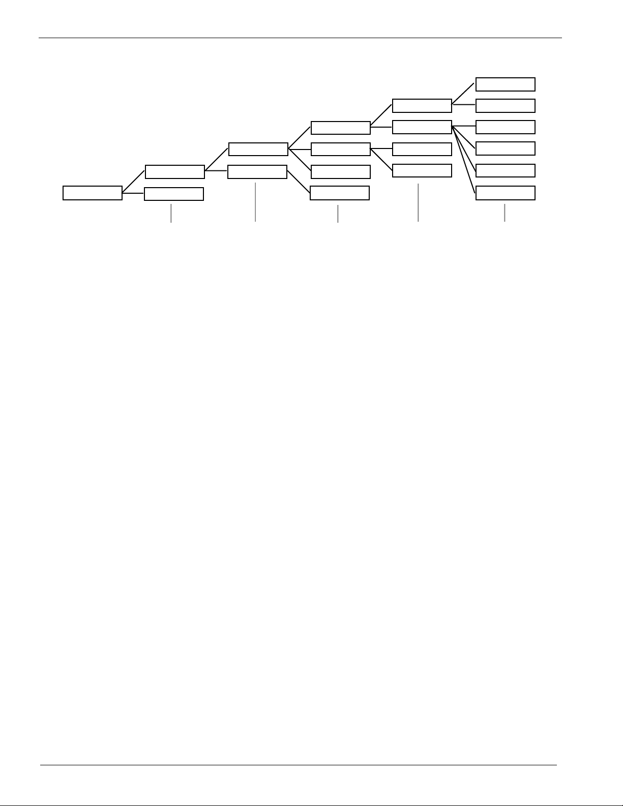
The instruNet Data Tree
instruNet stores field settings in a hierarchical data tree illustrated in figure 2.4.
2-13
Ch 2 instruNet Tutorial
Field
Setting Group
# {-32K...32K}
Channel
# {1...}
Module #
{1...32}
Device #
{0...32}
Network #
{0...32}
Figure 2.4 Network Hierarchy for instruNet
To access a piece of information, you must supply an address within this data tree.
This address consists of 6 parameters, as described below:
Network Number If 0, this refers to the Driver itself (e.g. plot lines or dots in the
Record displays); otherwise, this number refers to an instruNet
Controller board, where the first board found in the computer
is designated Network Number 1, the 2nd board found is
Network #2, etc.
Device Number This refers to hardware devices (e.g. Model 100) attached to
an instruNet Controller board, where the hardware Device
closest to the Controller is Device #1, the next device is
Device #2, etc.
Module Number This refers to the module within a hardware device. At this
time, all Devices have only 1 module that is referred to as
Module #1.
Channel Number This refers to a specific channel in a hardware device. Each
channel typically corresponds to a physical wire somewhere,
such as a voltage input, voltage output, digital input, or digital
output. For example, in the Model 100, the screw terminal
marked "Ch1 Vin+" is Channel #1 and is a voltage input.
Setting Number Each channel includes different Settings areas such as:
lowpass filter settings, highpass filters settings, Hardware
settings, etc. It is here that one selects a settings group (e.g.
Lowpass Filter fields have a Settings Number of -9).
Field Number This is the Field Number {1..8} within a settings group. For
example, in the Lowpass Filter settings group, the cut-off
frequency in Hertz is stored in Field #5.
2-14
 Loading...