

Omega Power Equipment JPEG2000 Triplex, Triplex User Manual

U
U
U
s
s
s
e
e
e
r
r
r
’
’
’
s
s
s
M
M
M
a
a
a
n
n
n
u
u
u
a
a
a
l
l
l
[V1.98-R00/061003-5700]
Standalone-Type
Digital Video Recorder
JPEG2000/Triplex
4
4
4
/
/
/
8
8
8
/
/
/
1
1
1
6
6
6
-
-
-
c
c
c
h
h
h
.
.
.
D
D
D
i
i
i
g
g
g
i
i
i
t
t
t
a
a
a
l
l
l
V
V
V
i
i
i
d
d
d
e
e
e
o
o
o
R
R
R
e
e
e
c
c
c
o
o
o
r
r
r
d
d
d
e
e
e
r
r
r


IMPORTANT SAFEGUARDS
1. Read Instructions - All the safety and operating instructions
should be read before the unit is operated.
2. Retain Instructions - The safety and operating instructions
should be retained for future reference.
3. Heed Warnings - All warnings on the unit and in the
operating instructions should be adhered to.
4. Follow Instructions - All operating and use instructions should
be followed.
5. Cleaning - Unplug the unit from the outlet before cleaning.
Do not use liquid cleaners or aerosol cleaners. Use a damp
cloth for cleaning.
6. Attachments - Do not use attachments not recommended by
the product manufacturer as they may cause hazards.
7. Water and Moisture - Do not use this unit near water - for
example, near a bath tub, wash bowl, kitchen sink, or laundry
tub, in a wet basement, near a swimming pool, in an
unprotected outdoor installation, or any area which is
classified as a wet location.
8. Accessories - Do not place this unit on an unstable stand,
tripod, bracket, or mount. The unit may fall, causing serious
injury to a person and serious damage to the unit. Use only
with a stand, tripod, bracket, or mount recommended by the
manufacturer, or sold with the product. Any mounting of the
unit should follow the manufacturer's instructions, and should
use a mounting accessory recommended by the manufacturer.
An appliance and cart combination should be moved with
care. Quick stops, excessive force, and uneven surfaces may
cause the appliance and cart combination to overturn.
9. Ventilation - Openings in the enclosure, if any, are provided
for ventilation and to ensure reliable operation of the unit and
to protect it from overheating. These openings must not be
blocked or covered. This unit should not be placed in a builtin installation unless proper ventilation is provided or the
manufacturer's instructions have been adhered to.
10. Power Sources - This unit should be operated only from the
type of power source indicated on the marking label. If you
are not sure of the type of power supply you plan to use,
consult your appliance dealer or local power company. For
units intended to operate from battery power, or other sources,
refer to the operating instructions.
11. Grounding or Polarization - This unit may be equipped with a
polarized alternating-current line plug (a plug having one
blade wider than the other). This plug will fit into the power
outlet only one way. This is a safety feature. If you are unable
to insert the plug fully into the outlet, try reversing the plug.
If the plug should still fail to fit, contact your electrician to
replace your obsolete outlet. Do not defeat the safety purpose
of the polarized plug. Alternately, this unit may be equipped
with a 3-wire grounding-type plug, a plug having a third
(grounding) pin. This plug will only fit into a grounding-type
power outlet. This is a safety feature. If you are unable to
insert the plug into the outlet, contact your electrician to
replace your obsolete outlet. Do not defeat the safety purpose
of the grounding-type plug.
12. Power-Cord Protection - Power-supply cords should be
routed so that they are not likely to be walked on or pinched
by items placed upon or against them, paying particular
attention to cords and plugs, convenience receptacles, and the
point where they exit from the appliance.
13. Power Lines - An outdoor system should not be located in the
vicinity of overhead power lines or other electric light or
power circuits, or where it can fall into such power lines or
circuits. When installing an outdoor system, extreme care
should be taken to keep from touching such power lines or
circuits as contact with them might be fatal. U.S.A. models
only –refer to the National Electrical Code Article 820
regarding installation of CATV systems.
14. Overloading - Do not overload outlets and extension cords as
this can result in a risk of fire or electric shock.
15. Object and Liquid Entry - Never push objects of any kind into
this unit through openings as they may touch dangerous
voltage points or short-out parts that could result in a fire or
electric shock. Never spill liquid of any kind on the unit.
16. Servicing - Do not attempt to service this unit yourself as
opening or removing covers may expose you to dangerous
voltage or other hazards. Refer all servicing to qualified
service personnel.
17. Damage Requiring Service - Unplug the unit from the outlet
and refer servicing to qualified service personnel under the
following conditions:
a. When the power-supply cord or plug is damaged.
b. If liquid has been spilled, or objects have fallen into the
unit.
c. If the unit has been exposed to rain or water.
d. If the unit does not operate normally by following the
operating instructions. Adjust only those controls that are
covered by the operating instructions, as an improper
adjustment of other controls may result in damage and
will often require extensive work by a qualified
technician to restore the unit to its normal operation.
e. If the unit has been dropped or the cabinet has been
damaged.
f. When the unit exhibits a distinct change in performance—
this indicates a need for service.
18. Replacement Parts - When replacement parts are required, be
sure the service technician has used replacement parts
specified by the manufacturer or have the same characteristics
as the original part. Unauthorized substitutions may result in
fire, electric shock or other hazards.
19. Safety Check - Upon completion of any service or repairs to
this unit, ask the service technician to perform safety checks
to determine that the unit is in proper operating condition.
20. Coax Grounding - If an outside cable system is connected to
the unit, be sure the cable system is grounded. U.S.A. models
only--Section 810 of the National Electrical Code,
ANSI/NFPA No.70-1981, provides information with respect
to proper grounding of the mount and supporting structure,
grounding of the coax to a discharge unit, size of grounding
conductors, location of discharge unit, connection to
grounding electrodes, and requirements for the grounding
electrode.
21. Lightning - For added protection of this unit during a
lightning storm, or when it is left unattended and unused for
long periods of time, unplug it from the wall outlet and
disconnect the cable system. This will prevent damage to the
unit due to lightning and power-line surges.

FCC & ICES INFORMATION
(U.S.A. AND CANADIAN MODELS ONLY)
WARNING - This equipment has been tested and found to
comply with the limits for a Class A digital device, pursuant to
Part 15 of the FCC Rules and ICES-003 of Industry Canada.
These limits are designed to provide reasonable protection
against harmful interference when the equipment is operated in a
residential installation. This equipment generates, uses and can
radiate radio frequency energy and, if not installed and used in
accordance with the instructions, may cause harmful interference
to radio communications. Operation of this equipment in a
residential area is likely to cause harmful interference in which
case the user will be required to correct the interference at his
own expense. Intentional or unintentional changes or
modifications not expressly approved by the party responsible for
compliance shall not be made. Any such changes or
modifications could void the user’s authority to operate the
equipment.
If necessary, the user should consult the dealer or an experienced
radio/television technician for corrective action. The user may
find the following booklet prepared by the Federal
Communications Commission helpful: "How to Identify and
Resolve Radio-TV Interference Problems". This booklet is
available from the U.S. Government Printing Office, Washington,
DC 20402, Stock No.004-000-00345-4.
SAFETY PRECAUTIONS
This label may appear on the bottom of the unit due to space
limitations.
The lightning flash with an arrowhead
symbol, within an equilateral triangle, is
intended to alert the user to the presence of
un-insulated "dangerous voltage" within the
product's enclosure that may be of sufficient
magnitude to constitute a risk of electric
shock to persons.
The exclamation point within an equilateral
triangle is intended to alert the user to
presence of important operating and
maintenance (servicing) instructions in the
literature accompanying the appliance.
Attention: Installation should be performed
by qualified service personnel only in
accordance with the National Electrical Code
or applicable local codes.
Power Disconnect. Units with or without
ON-OFF switches have power supplied to the
unit whenever the power cord is inserted into
the power source; however, the unit is
operational only when the ON-OFF switch is
in the ON position. The power cord is the
main power disconnect for all units.
Warning
This is a class A product. In a domestic environment this
product may cause radio interference in which case the
use
r
may be required to take ade
q
uate measures.
WARNING
TO PREVENT FIRE OR SHOCK HAZARD, DO NOT
EXPOSE UNITS NOT SPECIFICALLY DESIGND FOR
OUTDOOR USE TO RAIN OR MOISTURE.

INDEX
1. UNPACKING ----------------------------------------------------------------------------------------------- 6
2. SERVICE --------------------------------------------------------------------------------------------------- 6
3. INSTALLATION ------------------------------------------------------------------------------------------- 6
3.1 SYSTEM DIAGRAM --------------------------------------------------------------------------------------- 6
3.2 INSTALL HDD --------------------------------------------------------------------------------------------- 6
3.3 BACK PANEL CONNECTION ------------------------------------------------------------------------ 7
4. KEYS & INDICATORS --------------------------------------------------------------------------------- 8
5. START UP -------------------------------------------------------------------------------------------------- 9
5.1 PRE-CAUTIONS ----------------------------------------------------------------------------------------- 9
5.2 BOOTING (FIRST SCREEN) ------------------------------------------------------------------------- 9
6. SETUP ------------------------------------------------------------------------------------------------------ 9
6.1 SYSTEM MENU ------------------------------------------------------------------------------------------ 9
6.2 DISPLAY SETUP ----------------------------------------------------------------------------------------- 9
6.3 CONFIGURATION --------------------------------------------------------------------------------------- 10
6.3.1 HDD Management --------------------------------------------------------------------------------------- 10
6.3.2 Time/Date Setup ------------------------------------------------------------------------------------------ 10
6.3.3 Camera Setup --------------------------------------------------------------------------------------------- 10
6.3.4 Interval Setup ---------------------------------------------------------------------------------------------- 12
6.3.5 Alarm Setup ------------------------------------------------------------------------------------------------ 12
6.3.6 Event Popup Setup -------------------------------------------------------------------------------------- 12
6.3.7 Buzzer Setup ---------------------------------------------------------------------------------------------- 12
6.3.8 Password Setup ------------------------------------------------------------------------------------------ 13
6.3.9 System information --------------------------------------------------------------------------------------- 13
6.4 RECORD SETUP ----------------------------------------------------------------------------------------- 13
6.4.1 Record Configuration ------------------------------------------------------------------------------------ 13
6.4.2 Schedule Setup ------------------------------------------------------------------------------------------- 14
6.4.3 Holiday Setup ---------------------------------------------------------------------------------------------- 14
6.5 BACK-UP ---------------------------------------------------------------------------------------------------- 15
6.6 EXTERNAL DEVICE ------------------------------------------------------------------------------------- 15
6.6.1 TCP/IP Setup ---------------------------------------------------------------------------------------------- 15
6.6.2 RS-232C Setup ------------------------------------------------------------------------------------------- 16
6.6.3 Pan/Tilt Setup ---------------------------------------------------------------------------------------------- 16
6.7 FACTORY DEFAULT ----------------------------------------------------------------------------------- 17
6.8 LANGUAGE ----------------------------------------------------------------------------------------------- 17
7. OPERATION ---------------------------------------------------------------------------------------------- 18
8. NETWORK CONFIGURATION ---------------------------------------------------------------------- 21
9. REGISTRATION DVR at DDNS SERVICE WEBSITE --------------------------------------- 26
10. NETWORK VIEWER ----------------------------------------------------------------------------------- 30
11. WEB VIEWER -------------------------------------------------------------------------------------------- 35
12. WEB CLIENT --------------------------------------------------------------------------------------------- 36
13. CD PLAYER ----------------------------------------------------------------------------------------------- 37
14. HOW TO UPDATE THE LATEST SOFTWARE THROUGH CD -------------------------- 39
15. HOW TO UPDATE THE LATEST SOFTWARE THROUGH USB ------------------------ 40
16. FAQ ---------------------------------------------------------------------------------------------------------- 43
6
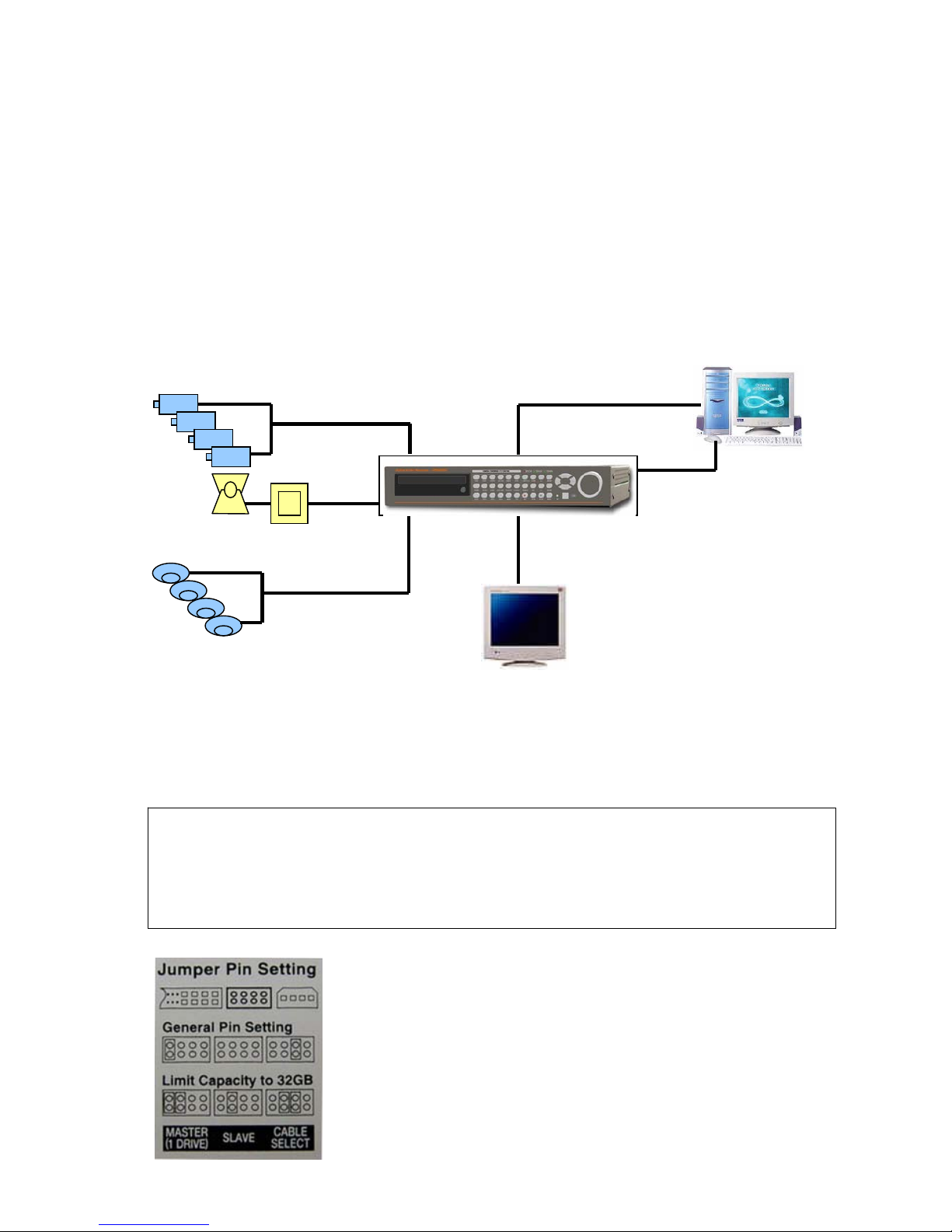
RS-485
A
LARM IN 1-4
PAN/TILT RECEIVER
1. UNPACKING
z Unpack carefully. This is electronic equipment and should be handled carefully.
z Check to ensure that the following items are included for applicable modules are ordered.
- Digital Video recorder.
- Power Adapter.
- Accessories pack.
- User’s Manual.
2. SERVICE
z If the unit ever needs repair service, the customer should contact the sales agency.
3. INSTALLATION
3.1 SYSTEM DIAGRAM
3.2 INSTALL HDD
z HDD should be up to 7200rpm. Capacity of HDD is unlimited. We strongly recommend Maxtor and Hitachi HDD.
z Connect Main Board and HDD1 using IDE cable and HDD power cable.
z The jumper setting of HDD1 should be on Master if you install only one HDD.
z The jumper setting of HDD1 should be on Master and HDD2 should be on Slave if you install two HDDs.
z CD Writer model: HDD must be Master, CD-Writer must be Slave.
z Example of HDD Jumper Setup.
(Caution)
(1) When Hard Disk Add or Exchange, Must System Off Properly (System Off by Power Button). If not, it’s a Cause
of Fatal Hard Disk Error.
(2) After install HDD, start DVR and operate the followings 3 STEP.
z Set the time/date.
z Set at Factory Default in SETUP Menu.
z Clear HDD in SETUP Menu.
COMPUTER
RS-232C
ETHERNET
MON
MONITOR
VIDEO IN 1-4
SENSOR 1-4
CAMERA 1-4
7
3.3 BACK PANEL CONNECTION
3.3.1 Connecting Video-In/Out
z Connect camera to ‘VIDEO-IN’.
z Connect to ‘VIDEO-OUT’ if you are using other equipments with camera input.
3.3.2 Connecting Monitor (MON, VGA, VCR)
z The system supports you to select one of the monitors out of normal CCTV monitor and PC monitor. Please connect to
‘MON’ if you are using CCTV monitor while you are required to connect to ‘VGA’ for PC monitor. Please use ‘VCR’
connectorfor connection with analog VCR or Video printer.
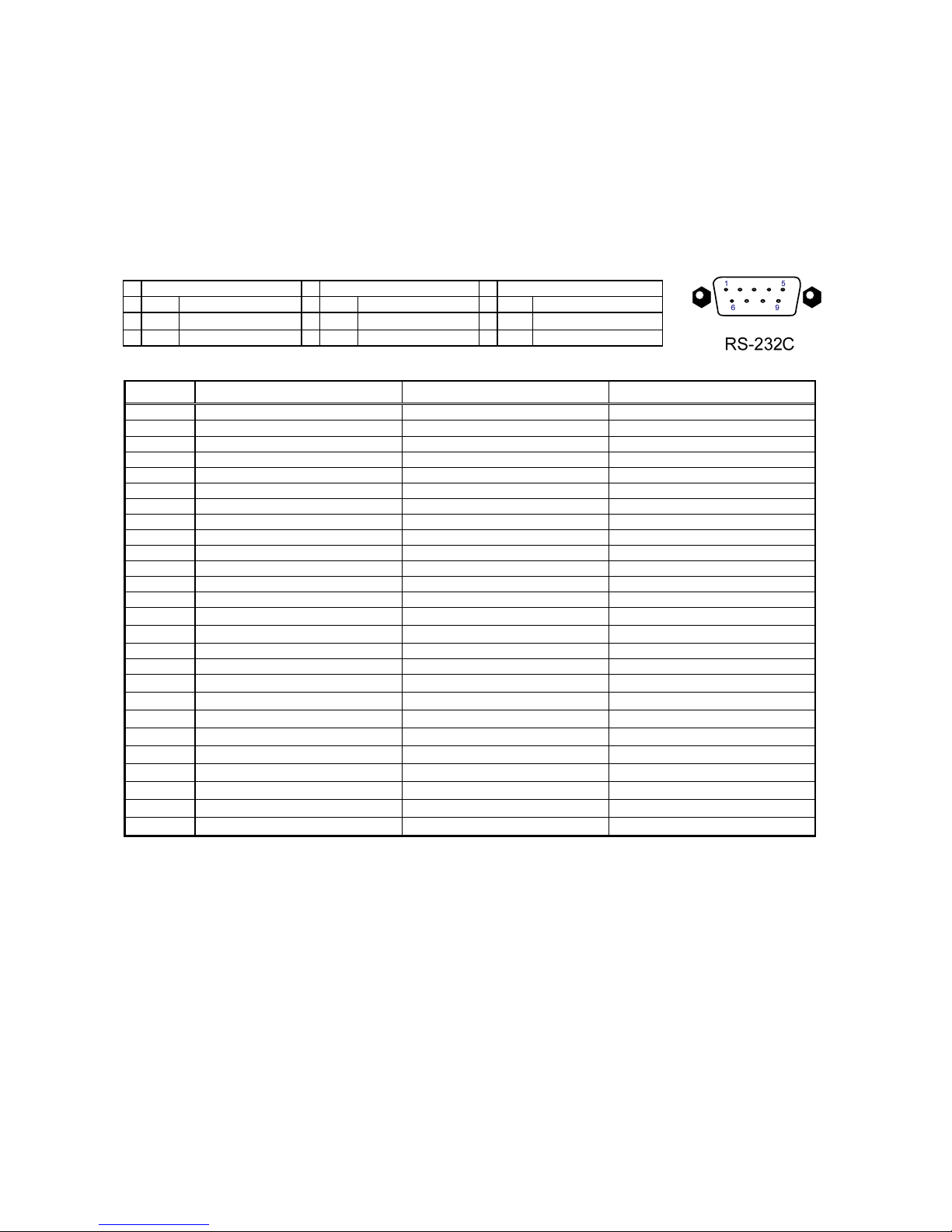
3.3.3 RS-232C
z Connect to external device as PC using RS-232C to control the DVR
No Description No Description No Description
1 DCD Data Carrier Detect 4 DTR Data Terminal data 7 RTS RS232C: Rx/Tx data
2 RxD Receive data 5 GND Signal Ground 8 CTS RS232C: Rx/Tx data
3 TxD Transmit data 6 DSR Data Set Ready 9
3.3.4 Alarm / RS-485
Pin No. 4-channel 8-channel 16-channel
1
RS-485 D- RS-485 D- RS-485 D-
2
RS-485 D+ RS-485 D+ RS-485 D+
3
Relay-Out Common Relay-Out Common GND
4
Relay-Out NC Relay-Out NC Relay-Out Common
5
Relay-Out NO Relay-Out NO Relay-Out NC
6
Sensor-Input GND GND Relay-Out NO
7
Sensor-Input 4 GND GND
8
Sensor-Input 3 Sensor-Input 8 Sensor-Input 16
9
Sensor-Input 2 Sensor-Input 7 Sensor-Input 15
10
Sensor-Input 1 Sensor-Input 6 Sensor-Input 14
11
Sensor-Input 5 Sensor-Input 13
12
Sensor-Input 5 GND
13
Sensor-Input 3 Sensor-Input 12
14
Sensor-Input 2 Sensor-Input 11
15
Sensor-Input 1 Sensor-Input 10
16
Sensor-Input 9
17
GND
18
Sensor-Input 8
19
Sensor-Input 7
20
Sensor-Input 6
21
Sensor-Input 5
22
GND
23
Sensor-Input 4
24
Sensor-Input 3
25
Sensor-Input 2
26
Sensor-Input 1
3.3.5 Connecting TCP/IP (Ethernet)
z Connect LAN to ‘ETHERNET’ connector.
3.3.6 Connecting Power
z Connect included power supply to ‘12VDC’ connector. Input voltage of power supply is from 100 VAC ~ 240 VAC.
z It’s suggested not to use ‘SUB’ connector for the product equips with dual ‘12VDC’ connector (MAIN & SUB).
3.3.7 NOTES
1. ‘MON’ Connector: Set impedance switch on the back of monitor to 75 Ω if only the monitor is connected to ‘MON’
connector. Set impedance switch on the back of monitor to HIGH Z (HIGH IMPEDANCE) if monitor is connected to
‘MON’ connector and other units (VCR. etc.) are connected behind to monitor. The last unit always has to be set to 75
Ω.
2. ‘VIDEO-IN’ Connectors: It is not necessary to set 75
Ω if you are connecting cameras to connectors in upper row only.
You cannot connect cameras to lower row connectors.
3. ‘VIDEO-OUT’ Connector: If there are other units are connected to ‘VIDEO-OUT’, impedance of the last unit always has to
be set to 75
Ω. Do not connect Camera to ‘VIDEO-OUT’.
4. Any voltage can not be applied to alarm input.
5. To avoid accidental deletion of hard data, please press the MENU key on the front of the DVR before powering off the
unit.

8
4. KEYS & INDICATORS
4.1 FRONT PANEL
4.2 KEYS & INDICATORS
Keys / Indicator Operating Function Programming Function
1 ~ 16
•Set up each camera in Full Screen mode
•Control PTZ camera
•Input Password (#1~#10)
MODE
•Switch to split display
•Changes screen mode (Full screen, Split screen)
PTZ
•On/Off for PTZ control mode
MENU
•Enter the SETUP Mode
ENTER
•Select menu option
NEXT
•Move to next page (step)
(+)
•Increase the option value in the menu
(-)
• Decrease the option value in the menu
J.SHUTTLE
•On/Off for Jog/Shttle search mode
SEARCH
•Search recorded data on HDD
REC
•Emergency Record at continuous, 120ips,
SUPER FINE size
STOP
•Stop of Emergency Record
•Stop Playback.
PLAY
•Playback of recorded data on HDD
ZOOM/A
•(Short Press): Audio On/Off (only for Audio version)
•(Long Press): Zooming an image
FRZ
•Freezing an image
▲, ▼ •Change playback speed •Move cusor up / down
◄, ► •Change Playback direction (Backward / Forward) •Move cusor left / right
USB
•Firmware upgrade by connecting PC
JOG/SHUTTLE
•Jog left turning: Move backward to next image
•Jog right turning: Move forward to next image
•Shuttle left turning: Decrease playback speed
•Shuttle right turning: Increase playback speed
•Jog left turning: Decrease option value
•Jog right turning: Increase option value
•Shuttle left turning: Decrease option value
•Shuttle right turning: Increase option value
INDICATORS
REC / PLAY / HDD STOP / ETHERNET / J.SHUTTLE
9
5. START UP
5.1 PRE-CAUTIONS
z You are firmly requested to turn off the power only in
Setup mode of the MENU. Forced disconnection of
Power supply in Record mode can cause malfunction
of HDD.
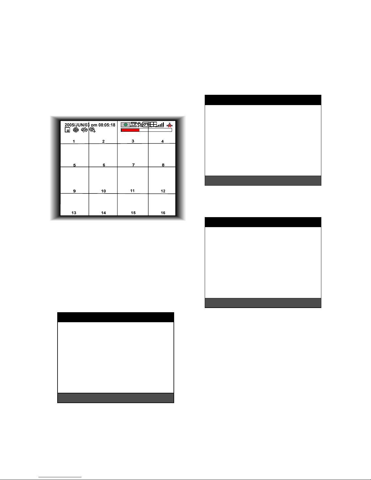
5.2 BOOTING (FIRST SCREEN)
z Plug in the Power Supply. If power is properly
connected, the system will start booting. It takes about
30 seconds to boot and display the first screen. The
screen is recording screen mode.
z Before the initial operation, you must set Time/Date,
set FACTORY DEFAULT, and then clear HDD, even
though it is brand new one. It is to make the DVR and
HDD ready for proper operation. Starting recording
without FACTORY DEFAULT setting and HDD clear
will cause malfunction. FACTORY Refer to ‘SETUP’
for getting how to proceed with DEFAULT setting and
HDD clear.
6. SETUP
6.1 SYSTEM MENU
z Press MENU key to enter the SYSTEM MENU and
you will see as below.
z Enter password with Channel Number key from No.1
to No.10 on the front of the DVR unit. (Maximum of 8
digits are available)
z Factory default password is blank. For log-in, just
press MENU key and then ENTER key.
z Administrator: If the password entered matches
previously set password, ‘LOGIN ADMIN’ message
appears and you can enter into SYSTEM SETUP. If
the password entered does not match previously set
password, the DVR unit goes back to live display
mode.
z Factory default passwords are as below.
- ADMIN: Blank (ENTER key)
- MANAGER: ‘ 1 ’
- USER 1~USER 8: ‘ 2 ’ ~ ’ 9 ’
z Put in correct Password and press ENTER key to
display SYSTEM MENU as below.
6.2 DISPLAY SETUP
z Select DISPLAY SETUP and press ENTER key will
show as below.
6.2.1 Screen Display
z Setting up the screen display in LIVE mode and
PLAYBACK mode.
z Select the sub-menu which you would like to set using
▲▼ keys and then change ON/OFF with ENTER key.
- TIME/DATE: Display time & date.
- ICON DISPLAY: Display function setting status.
- DVR STATUS: Display system setting status.
- REC / PLAY BAR: Display record / playback status.
- CAMERA TITLE: Display camera title.
6.2.2 Monitor Setup
z VGA SETUP: VGA option card enables to connect
TFT LCD monitor or CRT type PC monitor to DVR
unit. To connect TFT LCD monitor or CRT type PC
monitor to DVR unit, select resolution as follows using
[+] [−] keys. After setting the below option, press
ENTER key then the DVR unit will set VGA resolution
automatically. VGA option card supports following
resolution, and choose best resolution that
match TFT LCD monitor or CRT type PC monitor to
SYSTEM MENU
DISPLAY SETUP
CONFIGURATION
RECORD SETUP
BACK-UP
EXTERNAL DEVICE
FACTORY DEFAULT
LANGUAGE ENGLISH
LANGUAGE SELECT: + -
SELECT MENU : ▲▼, & [ENTER
]
DISPLAY SETUP
SCREEN DISPLAY
MONITOR SETUP
SELECT MENU : ▲▼, & [ENTER
]
DVR LOG-IN
ENTER PASSWORD
_ _ _ _ _ _ _ _
INPUT YOUR OWN PASSWORD
TO EXIT, PRESS [MENU]

10
be connected to DVR unit.
- 640X480 / 60Hz
- 800X600 / 60Hz
- 1024X768 / 60Hz
- 640X480 / 75Hz
- 800X600 / 75Hz
- 1024X768 / 75Hz
z COLOR BAR TEST: Adjust color tone of monitor.
6.3 CONFIGURATION
z Select CONFIGURATION and press the ENTER key.
6.3.1 HDD Management
z HDD SETUP: Select HDD MANAGEMENT > HDD
SETUP and press ENTER key to display following
screen.
- This page includes information about start and end of
recording, location of recorded data, or location of last
playback on HDD. In addition, users can delete all the
data on HDD.
- On the HDD CLEAR sub-menu, press the ENTER key
to delete all image data on HDD. The system will ask
password for verification. After you clear all data on
HDD, status of HDD CLEAR changes from IN USE to
EMPTY. When you clear HDD, event list is deleted,
too.
- If you selected OVERWRITE in Record Setup, the
HDD STATUS presented as OVERWRITE.
z HDD INFORMATION: Select HDD MANAGEMENT >
HDD INFORMATION and press ENTER key to
display following screen. This menu will show the
physical information of HDD in DVR.
6.3.2 Time/Date Setup
z Set time and date of DVR system which is very
important for search with time and date of the event.
time and date set by manufacturer is different from
local time of user, and user must set time and date
exactly in the first operation.
z Set time & date using
▲▼ keys and [-][+] keys or
Jog shuttle.
6.3.3 Camera Setup
z CAMERA TITLE: Input title of each camera. Move to
channel you want to change using
◀▶ keys and
then change the title using [-] [+] keys. When
modification is finished, press ENTER key. To exit to
previous menu, press MENU key.
HDD SETUP
STATUS HDD TIME/DATE
-----------------------------------------------------------BEGIN MASTER 2005 / 04 / 08
12:12:05
RECORD MASTER 2005 / 04 / 09
15:09:58
PLAY MASTER 2005 / 04 / 08
19:44:31
HDD STATUS NORMAL
HDD CLEAR IN USE
HDD CLEAR: [ENTER], EXIT: [MENU]
HDD INFORMATION
[MASTER]
MODEL Maxtor 6Y080L0
SPEED PIO-4
SIZE 81,964,302,336 BYTES
START 2005/04/08 10:08:56
END 2005/04/08 11:08:56
[SLAVE]
MODEL
SPEED
SIZE
START ----/--/-- --:--:--
END ----/--/-- --:--:--
TO EXIT, PRESS [MENU]
TIME/DATE SETUP
YEAR
MONTH
DAY 2005 / JUN /11
HOUR
MINUTE PM14:06:45
SECOND
DATE FORMAT ASIA
TIME FORMAT 12 HOUR
MONTH FORMAT ENGLISH
SELECT : ▲▼, CHAGE VALUE : +-
CAMERA SETUP
CAMERA TITLE
CAMERA COLOR SETUP
CAMERA ACTIVE SETUP
MOTION SETUP
SELECT MENU : ▲▼, & [ENTER
]
(Note) In the booting process, DVR unit with VGA
option card takes some seconds more to set
parameters.
CONFIGURATION
HDD MANAGEMENT
TIME/DATE SETUP
CAMERA SETUP
INTERVAL SETUP
ALARM SETUP
EVENT POPUP SETUP
BUZZER SETUP
PASSWORD SETUP
SYSTEM INFORMATION
SELECT MENU : ▲▼, & [ENTER]

11
z CAMERA COLOR STUP: Adjust image color. Move
to each element using
▲▼ keys and adjust using
[-] [+] keys or Jog shuttle.
- CHANNEL: Select camera.
- BRIGHTNESS: Adjust image brightness (-32~ 31).
- CONTRAST: Adjust color contrast (-32 ~ 31).
- SATURATION: Adjust color saturation (-32 ~ 31).
- HUE: Adjust color hue (-32 ~ 31)
z CAMERA ACTIVE SETUP: With ▲▼
◀▶ keys,
move to option to be changed, and press ENTER key
to select [ON/OFF]. If it is set at LIVE [OFF] and REC
[ON], DVR system records, but does not show live
image of set channel.
- STATUS: Shows if image from a specific channel is
coming for live display and recording. In normal
camera condition, it is ACTIVE, but LOSS is displayed
when the cable is disconnected or camera is not
working.
- LIVE: Decides whether to show LIVE screen image or
not.
- REC: Decides whether to record relevant channel or
not.
z MOTION SETUP: You can set sensitive of motion
detection in 4 steps, detection window number,
motion detection area and others in relation to motion
recording in this menu.
z MOTION CONFIGURATION
- CHANNEL: Select camera.
- SENSITIVITY GRADE: Adjusts sensitivity of motion
detection. Latest setting of a channel changes the rest
of channels to be one and same all at once. (1:LOW,
2:MEDIUM, 3:HIGH, 4:VERY HIGH)
- MOTION DISPLAY TYPE: Showing cells with motion
detected differently from cells with no motion. Latest
setting of a channel changes the rest of channels to
be one and same all at once .
- RECORD DURATION: Whenever motion is detected
and it is set at Motion Recording mode, DVR
system records for RECORD DURATION from time
motion is detected. Latest setting of a channel
changes the rest of channels to be one and same all
at once. (1sec.~ 99 sec.) (Default: 5 sec.)
- NUMBER OF CELLS TO DETECT: This is to adjust
the number of motion cells per each channel
separately within the range of detection (01~ 16).
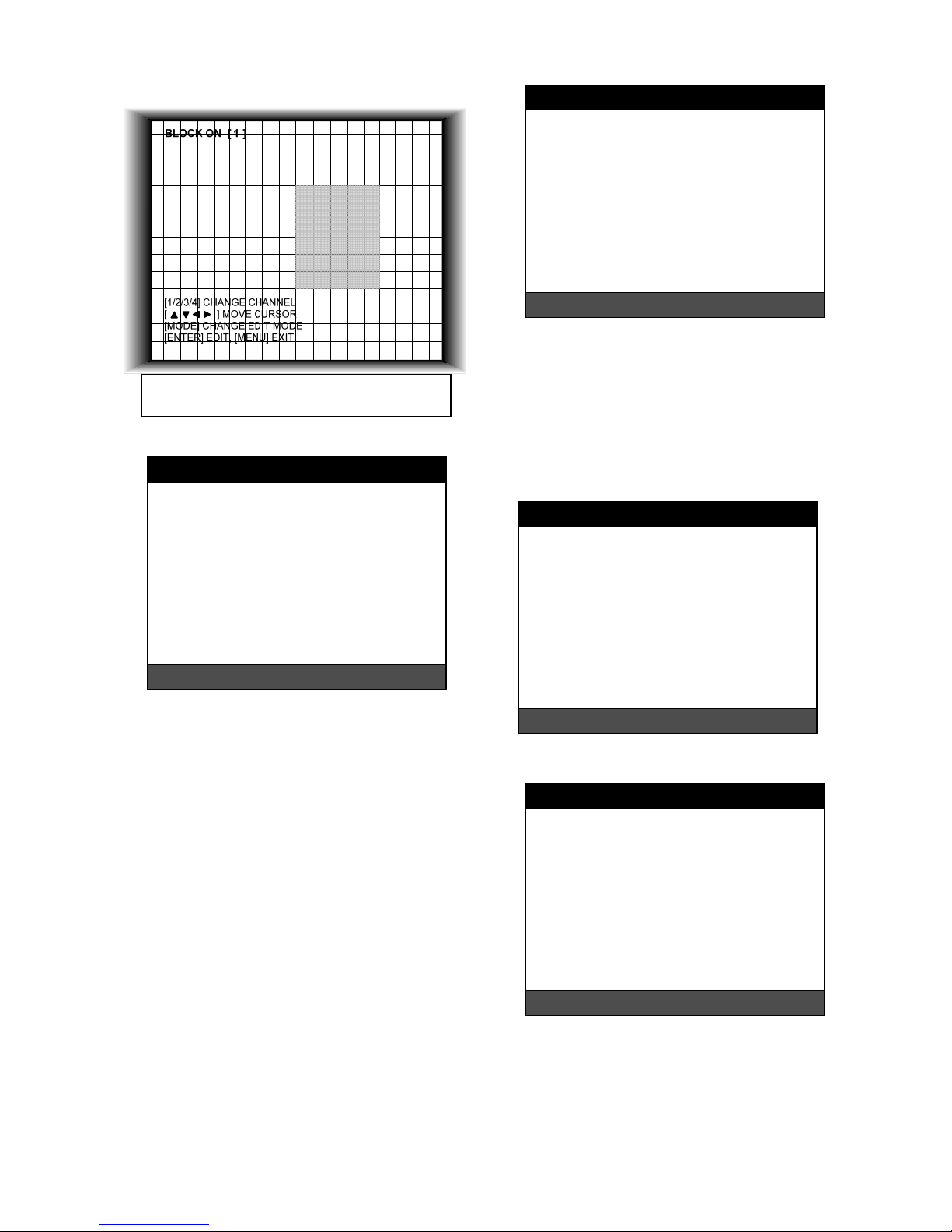
z MOTION MASK SETUP: Set motion detection area.
z ▲▼
◀▶ keys are for moving and ENTER key is for
selection, and MODE key is for changing mode of
MASK SETUP.
- CHANNEL: Select camera.
- CELL: Move to the location which you want to detect
and then press ENTER key. Highlighted cell area
means motion detection area.
- ALL ON: Set all cells as detection area. Use ENTER
key to set.
- ALL OFF: Set all cells as no-detection area. Use
ENTER key to set.
- BLOCK ON: Select detection area by block. Use
MODE key and press ENTER key to set ON.
CAMERA TITLE
CAMERA01 CAM -1
CAMERA02 CAM -2
CAMERA03 CAM -3
CAMERA04 CAM -4
CAMERA05 CAM -5
CAMERA06 CAM -6
CAMERA07 CAM -7
CAMERA08 CAM -8
[ENTER] : SELECT MODE
[ ▲/▼ ] SELECT CAMERA
0123456789 ABCDEFGHIJKLMNOPQ
RSTUVWXYZ!#-
[ ]
*+-,./:<=>?@ ◀▶
CAMERA COLOR SETUP
CHANNEL 1
BRIGHTNESS +0
CONTRAST +0
SATURATION +0
HUE +0
SELECT : ▲▼, CHANE VALUE : + -
CAMERA ACTIVE SETUP
CH STATUS LIVE REC
--------------------------------------------------------01 LOSS ON OFF
02 LOSS ON ON
03 LOSS ON ON
14 ACTIVE ON ON
15 LOSS ON OFF
16 LOSS ON ON
SELECT : ▲▼ ◀▶, & [ENTER]
MOTION SETUP
MOTION CONFIGURATION
MOTION MASK SETUP
SELECT : ▲▼, & [ENTER]
MOTION CONFIGURATION
CHANNEL 01
SENSITIVITY GRADE 4
MOTION DISPLAY TYPE OFF
RECORD DURATION 05 SEC
NUMBER OF CELLS TO DETECT 16
SELECT : ▲▼,CHANGE VALUE : + -
12
- BLOCK OFF: Select un-detection area by block. Use
MODE key and press ENTER key to set ON.
6.3.4 Interval Setup
z Set the switching time interval for SEQ or PIP function.
(1 sec. ~ 99 sec.)
- FULL SCREEN: set the sequencing switch time
interval in live full screen.
- PIP SCREEN: set the sequencing switch time interval
of PIP window.
- EVENT UPDATE TIME: Set the minimum time
interval of event to be listed in EVENT LIST. If EVENT
UPDATE TIME is set at 20 sec, only following event
happened 20 sec or more than 20 sec later previous
event shall be listed in EVENT LIST.
6.3.5 Alarm Setup
z Select ALARM SETUP and press ENTER to display
following screen.
- CHANNEL: Select camera.
- ALARM INPUT: Select type of alarm sensor input
connected to DVR unit (N.O or N.C). Use [-] [+] key to
set. N.O represents Normal Open type and N.C
Normal Close type. DISABLE represents not to use
alarm sensor connected to DVR.
- DURATION: Set the duration of alarm when an
ALARM is activated. (0 sec. ~ 300 sec.)
6.3.6 Event Popup Setup
z This Menu is to setup the images captured by the
Event displayed in Full Screen.
z Select Event popup setup and press ENTER key to
display following screen.
- CHANNEL: To select the camera number for Popup.
- POPUP ON/OFF: To decide the use of Popup.
- EVENT: To select Popup Events(A: Alarm, M: Motion)
- DURATION: To select Popup time.
6.3.7 Buzzer Setup
z Set parameters for buzzer (On or Off). Use ▲ ▼
◀
▶
keys and ENTER key.
- ALL: User can set all buzzers at On/Off at once by set
ALL at ON/OFF.
- KEY BEEP: buzz when button is pressed.
- VIDEO LOSS: buzz when video signal is lost.
- ALARM AC T I V E : buzz when alarm is activated.
- MOTION DETECT: buzz when motion is detected.
Highlighted Area: Motion Detection Area.
Non-highlighted Area: No Motion Detection Area.
INTERVAL SETUP
SWICHING INTERVAL
FULL SCREEN 01 SEC
PIP SCREEN 01 SEC
EVENT RECORD
EVENT UPDATE TIME 600 SEC
SELECT : ▲▼, CHANE VALUE : + -
A
LARM SETUP
CHANNEL CH01
ALARM INPUT N.O
DURATION 005
N.O .............. NORMAL OPEN
N.C .............. NORMAL CLOSE
- - - .............. DISABLE
SELECT : ▲▼, CHANE VALUE : + -
BUZZER SETUP
ALL - - KEY BEEP ON
VIDEO LOSS ON
ALARM ACTIVE ON
MOTION DETECT OFF
SELECT : ▲▼, & [ENTER]
EVENT POPUP SETUP
CHANNEL CH01
POPUP ON/OFF ON
EVENT AM
DURATION 03
SELECT : ▲▼, & [ENTER]

13
6.3.8 Password Setup
z Set user ID and password.
z Use ▲▼ keys to move to option and ◀▶ keys to set
user ID.
- ADMIN: Authorized to control and set all of functions.
- MANAGER: Authorized to control and set all of
functions but excluding HDD Clear.
- USER1~USER8: Authorized to control Display and to
set Language.
z The password must be consist of 1 to 8 digit number.
Just use Numbers button from 1 to 10 on the front
panel of DVR unit.
z To change password, user must input current
password and then input new password. And input
again new password to confirm.
z Default values
- ADMIN: Blank (press ENTER key)
- MANAGER: ‘1’
- USER 1 ~ USER 8: ‘2’ ~ ‘9’
z Change the user PASSWORD in the first operation is
recommended.
6.3.9 System Information
z DVR system information including firmware version,
hardware version, product ID, etc….
6.4 RECORD SETUP
z Select RECORD SETUP and press ENTER key will
show as below.
6.4.1 Record Configuration
z Use ▲▼ keys to move and [-] [+] keys to set values.
z OVERWRITE: Set overwrite or stop recording when
the HDD is full.
z MULTIPLEX
- DUPLEX: Playback & Networking.
- TRIPLEX: Playback & Recording & Networking.
z QUALITY: Set recording picture quality. Actually it is
fixing maximum data size of image for each picture
quality in 5 steps as follows.
- BASIC
- NORMAL
- ENHANCED
- FINE
- SUPER FINE
(Record Duration Table)
80GB 120GB 160GB 200GB
BASIC 34 H 50 H 66 H 82 H
NORMAL 24 H 37 H 49 H 61 H
ENHANCED 20 H 30 H 39 H 49 H
FINE 16 H 25 H 32 H 40 H
SUPER FINE 14 H 21 H 28 H 36 H
PASSWORD SETUP
USER ID ADMIN
USER PW -------NEW PW -------CONFIRM --------
[◀-▶] CHANGE USER ID
[K1-K10] INPUT PASSWORD
[ENTER] CHANGE PASSWORD
TO EXIT, PRESS [MENU]
SYSTEM INFORMATION
S/W VERSION VER 1.40
H/W VERSION REV-B, / ES3
PRODUCT ID
01S-2039-001008-AR-01
MASTER
Maxtor 6Y060L0
SLAVE
CD-R
SAMSUNG CD-R/RW SW-256B
TO EXIT, PRESS [MENU]
RECORD SETUP
RECORD CONFIGURATION
SCHEDULE SETUP
HOLIDAY SETUP
SELECT MENU : ▲▼, & [ENTER
]
RECORD CONFIGURATION
OVERWRITE ON
MULTIPLEX DUPEX
QUALITY SUPER FINE
RESOLUTION 60IPS@720*240
RECORD IN ALARM 1 / 1X
RECORD IN MOTION 1 / 1X
CONTINUOUS RECORD 1 / 1X
SELECT: ▲▼, CHANGE VALUE : + -
(Caution) DUPLEX MODE is recommended to
playback the images at a maximum frame rate.
But, it makes DVR not to record during search.

14
z RESOLUTION (8/16ch): Set recording resolution.
- 120 ips at 720x240(NTSC) , 100 ips at 720x288(PAL)
- 240 ips at 360x240(NTSC) , 200 ips at 360x288(PAL)
- 480 ips at 360x120(NTSC) , 400 ips at 360x144(PAL)
z RESOLUTION (4ch): Set recording resolution.
- 60 ips at 720x240(NTSC) , 50 ips at 720x288(PAL)
- 120 ips at 360x240(NTSC) , 100 ips at 360x288(PAL)
- 240 ips at 360x120(NTSC) , 200 ips at 360x144(PAL)
z RECORD IN ALARM: Set record speed (skip rate) in
ALARM record mode.
z RECORD IN MOTION: Set record speed (skip rate) in
MOTION record mode.
z CONTINUOUS RECORD: Set record speed (skip
rate) in CONTINUOUS record mode.
6.4.2 Schedule Setup
z To set Schedule Recording parameters, enter into
SCHEDULE SETUP and Press ENTER key.
z Unless you selected other recording mode, DVR
system records in Schedule Recording mode.
z In SCHEDULE REC SETUP, you set type of
recording for every time interval of 2 hours in each
day of the week.
z Schedule Recording set by manufacturer is recording
continuously at its full recording speed, and it means
DVR system record continuously at 120 ips in total at
720x240 resolution.
z Use [+] [−] key, to change the record type.
z Use MODE key to select edit type and move to the
time interval of a day of the week you want to change.
z To go next page, use NEXT key.
z RECORD TYPE;
- A: Alarm Recording.
- M: Motion Recording.
- C: Continuous Recording.
- AM: Alarm & Motion Recording.
- AC: Continuous & Alarm Recording.
- MC: Continuous & Motion Recording.
z EDIT TYPE;
- ALL: Set page by page at once.
- CLEAR ALL: Clear page by page.
- TIME CELL: Set a time cell at once.
- WEEK: Set a day of the week at once.
- TIME ZONE: Set a time zone at once.
6.4.3 Holiday Setup
z Users can set national holidays on calendar to record
just as setting for Sunday in SCHEDULE REC SETUP.
z Use MODE key to select a month and ▲▼
◀ ▶ keys
to move to a day, and press ENTER key to set a
holiday. Then color of date shall be changed to red,
as Sunday.
- EDIT HOLIDAY: Set as holiday.
- CLEAR MON DATA: Cancel the holiday set per
month.
- CLEAR ALL DATA: Cancel all holiday set.
SCHEDULE SETUP
SUN MON TUE WED THU FRI SAT
00-02 -M- AM- --C –-C --C --C --C
02-04 -M- AM- --C –-C --C --C --C
20-22 -M- AM- --C –-C --C --C --C
22-24 -M- AM- --C –-C --C --C --C
MODE: ALL 1 / 2
SELECT:▲▼◀▶ & [NEXT], EDIT:+ - &[MODE]
A: ALARM M: MOTION C: CONTINUOUS
HOLIDAY SETUP
◀ SEP ▶ 000 / 100
S M T W T F S
1 2 3
4 5 6 7 8 9 10
11 12 13 14 15 16 17
18 19 20 21 22 23 24
25 26 27 28 29 30
MODE : EDIT HOLIDAY
SELECT ▲▼◀▶, EDIT [ENTER] & [MODE]
(Note) Set record speed (skip rate)
- Range: 1/1x, 1/2x, ………. 1/999x
- If record resolution is set at 360x240, 1/1x = 120 ips,
1/2x = 60 ips, 1/3x = 40 ips, etc.
- ex: 1/2x) R->S->R->S…
- ex: 1/3x) R->S->S->R->S->S->R…
- ex: 1/4x) R->S->S->S->R->S->S…
(R: RECORD, S: SKIP)
(Note) The maximum holidays are 100 days.
(Note)
(1) Default quality set by manufacturer In Emergency
recording mode, recording quality is SUPER
FINE.
(2) To send more images via IP network and longer
recording time, set QUALITY at NORNAL or
ENHANCED and record at 360x240. (4ch:
360x240 or 360x120.)
(3) Data size of image in PAL system is a little bigger
than NTSC system, but the total recording time is
same as in NTSC system.
(Note)
Recording in half resolution is recommended for
higher recoding speed, and also to send more
images via IP network.
(Note)
(1) Unless user press REC key to record at full
resolution and in SUPER FINE picture quality,
DVR system records in SCHEDULE Record
mode.
(2) Pressing REC key → Emergency record
(Continuous recording in full performance)
[8/16ch: 120(100) ips at 720x240(720x288)]
[4ch: 60(50) ips at 720x240(720x288)]
(3) DEFAULT record mode for each time interval of a
day of the week set by manufacturer is
CONTINUOUS recording.
 Loading...