

Omega National Products SELECT, RHVBF10WH, RHVBB20WH Installation Instructions Manual

THESE INSTRUCTIONS SHOULD NOT BE FAXED OR REPRODUCED ON A DIGITAL COPIER.
AMERICAN WOODMARK CORPORATION PROVIDES THESE INSTRUCTIONS ON AN “AS IS”
BASIS AND DISCLAIMS ANY AND ALL LIABILITY FOR ANY INACCURACIES, OMISSIONS OR
TYPOGRAPHICAL ERRORS CAUSED BY ANY THIRD PARTY’S EQUIPMENT. When you use
these instructions, you are consenting to be bound by the provisions in this paragraph.
These instructions provide an illustrative method for installing American Woodmark
Corporation (“AWC”) cabinets and/or accessories. AWC’s instructions are not intended
to address every possible contingency that might be encountered during installation
or to endorse the use of any particular tools. AWC HEREBY EXPRESSLY DISCLAIMS ALL
LIABILITY FOR ANY CLAIMS FOR INJURY OR DEATH RELATED TO OR BASED UPON THE
USE OF THESE INSTALLATION INSTRUCTIONS AND ANY INSTALLATION INSTRUCTIONS
OTHERWISE PROVIDED BY AWC.
ESTAS INSTRUCCIONES NO SE DEBEN ENVIAR POR FAX NI SE DEBEN REPRODUCIR EN
UNA COPIADORA DIGITAL. AMERICAN WOODMARK CORPORATION PROPORCIONA
ESTAS INSTRUCCIONES “TAL COMO ESTAN” Y RENUNCIA A CUALQUIER Y A TODA
RESPONSABILIDAD POR CUALQUIER FALTA DE PRECISION, OMISION O ERROR
TIPOGRAFICO CAUSADO POR EL EQUIPO DE TERCERAS PERSONAS. Al utilizar estas
instrucciones, usted está aceptando estar sujeto a las disposiciones contenidas en este
párrafo. Estas instrucciones proporcionan un método ilustrativo para instalar los gabinetes
y/ o accesorios de American Woodmark Corporation (“AWC”). Las instrucciones de AWC
no tienen por objeto resolver toda contingencia posible que pudiera presentarse durante
la instalación ni recomendar el uso de una herramienta en particular. POR LA PRESENTE,
AWC RENUNCIA EXPRESAMENTE A TODA RESPONSABILIDAD POR CUALQUIER
RECLAMACION POR LESIONES O FALLECIMIENTO DERIVADOS DEL USO DE ESTAS
INSTRUCCIONES DE INSTALACION Y DE OTRAS INSTRUCCIONES DE INSTALACION QUE
AWC HAYA PROPORCIONADO DE ALGUNA OTRA FORMA.
99874 8/07
16 1/2"
10-0538-1A VS-17
4"
OPENING
10 1/4" X 19 1/2"
30" or 36"
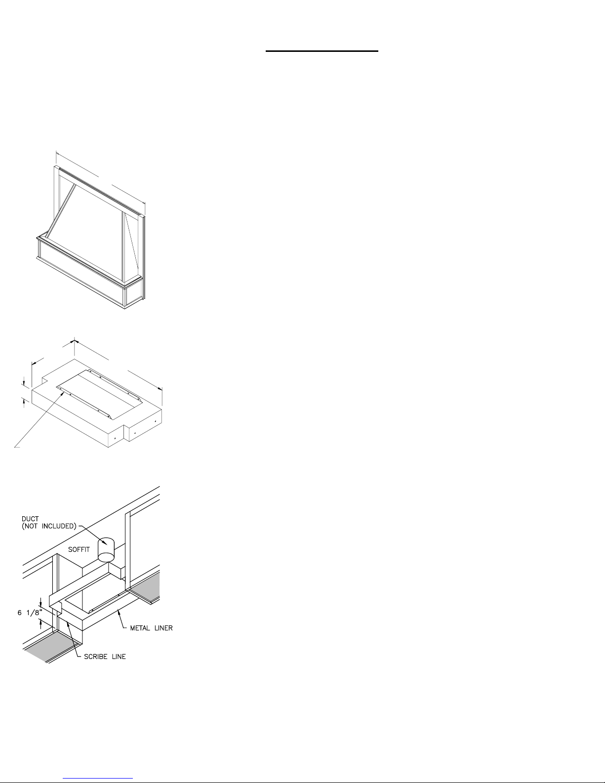
Figure 1
Figure 2
Figure 3
30" or 36"
I M P O R T A N T
INSTALLATION INSTRUCTIONS FOR
OMEGA NATIONAL PRODUCTS
SELECT SERIES RANGE HOOD AND LINER
Before installation may begin, the following components are required:
·
Fan unit, part number RHVBF10WH or
Blower unit, part number RHVBB20WH
•
Ducting System • Metal Liner • Decorative Wood Hood
A. The Wood Hood is composed of two separate components:
1. The decorative Hood Front, Figure 1
2. T-shaped Metal Liner, Figure 2
NOTE: T-shaped liner shipped with unit as standard.
3. The ventilation system (power module and ducting system) is not
included and must be purchased separately.
B. Installation: Metal Liner – T-Shaped, Figure 3
1. Measure up 6 1/8” from the bottom of adjacent cabinets. Scribe a level
line horizontally across depth of both cabinets.
2. Raise Metal Liner so that bottom edge of liner is level with scribed lines.
Use four (4) #8 x 1/2” screws (provided) to attach liner to adjacent
cabinets through pre-drilled holes in liner. (If metal liner is not flush to
cabinet sidewalls, it may be necessary to use a filler piece to avoid
bowing the liner.) Locate studs and place two #8 x 1 1/4” (supplied)
through rear of liner.
C. Installation of Omega National Products Select Series Wood Hood
1. Slide decorative hood front into position over T-Shaped liner and
between adjacent cabinets. Install the hood front by joining to adjacent
cabinets through the front frames using (4) #8 x 2 1/2” screws (not
provided).
D. Installation of Power Units
RHVBF10WH Fan Unit – see installation instructions enclosed with each
Power Unit.
RHVBB20WH Blower Unit - see installation instructions enclosed with each
Power Unit.
Source for all parts listed:
Your local distributor or: Omega National Products
1010 Rowe Street, Elkhart, IN 46516
574-295-5353 ▪ 574-295-5329(fax)
Form OME-054 06/2006 ©2006 Omega National Products
 Loading...