


Alarms & Remote Start
Automotive Data Solutions Inc.
INSTALL GUIDE
PL1
OL-BLADE-AL(TB)-PL1-EN
AvAiLABLE fOr : OL-BLADE-AL
Rev. Date: July 14, 2015
Doc. No.: ##22390##
U.S. PATENT NO. 8,856,780
The brand names and logos found in this guide are property of their respective owners. Automotive Data Solutions Inc. © 2015
NOTICE: The manufacturer will accept no responsibility for any electrical damage resulting from
improper installation of this product, be that either damage to the vehicle itself or to the installed
device. This device must be installed by a certified technician. This guide has been written for
properly trained technicians; a certain level of skill & knowledge is therefore assumed. Please
!
review the Installation Guide carefully before beginning any work.

INSTALL GUIDE
TRANSPONDER BYPASS
GM
U.S. Patent No. 8,856,780
Page 2 of 6 OL-BLADE-AL(TB)-PL1-EN 20150714
Doc. No.: ##22390##
INSTALL TYPE SELECTION
FEATURES
MAKE
MODEL
Century 97-99 1 •
LeSabre / Ultra 93-99 1 •
Park Avenue 91-96 1 •
Regal 96-99 1 •
BUICK
Riviera 94-99 1 •
Roadmaster 95-96 1 •
Skylark 96-98 2 •
Allante 91-93 1 •
Brougham 90-96 1 •
Concours 96-99 1 •
DeVille 89-99 1 •
Eldorado 91-02 1 •
CADILLAC
Fleetwood 90-96 1 •
Seville 91-97 1 •
Camaro 93-02 1 •
Caprice 94-96 1 •
Cavalier 95-99 2 •
Corvette 94-05 1 •
Lumina 95-99 1 •
Monte Carlo 95-99 1 •
CHEVROLET
Silverado 98 1 •
Tahoe 98 1 •
Sierra 98 1 •
GMC
Yukon 98 1 •
Achieva 96-98 2 •
Aurora 95-99 1 •
Cutlass Supreme 95-97 1 •
Eighty-Eight 95-99 1 •
LSS 97-99 1 •
OLDSMOBILE
Nighty-Eight 95-96 1 •
Regency 97-99 1 •
Bonneville 95-99 1 •
Firebird 93-02 1 •
Grand Am 95-98 2 •
Grand Prix 94-96 1 •
PONTIAC
Sunfi re 95-99 2 •
YEAR
INSTALL TYPE
DATA IMMOBILIZER BYPASS
Automotive Data Solutions Inc. © 2015
INSTALL GUIDE
TRANSPONDER BYPASS
GM
U.S. Patent No. 8,856,780
Page 3 of 6 OL-BLADE-AL(TB)-PL1-EN 20150714
Doc. No.: ##22390##
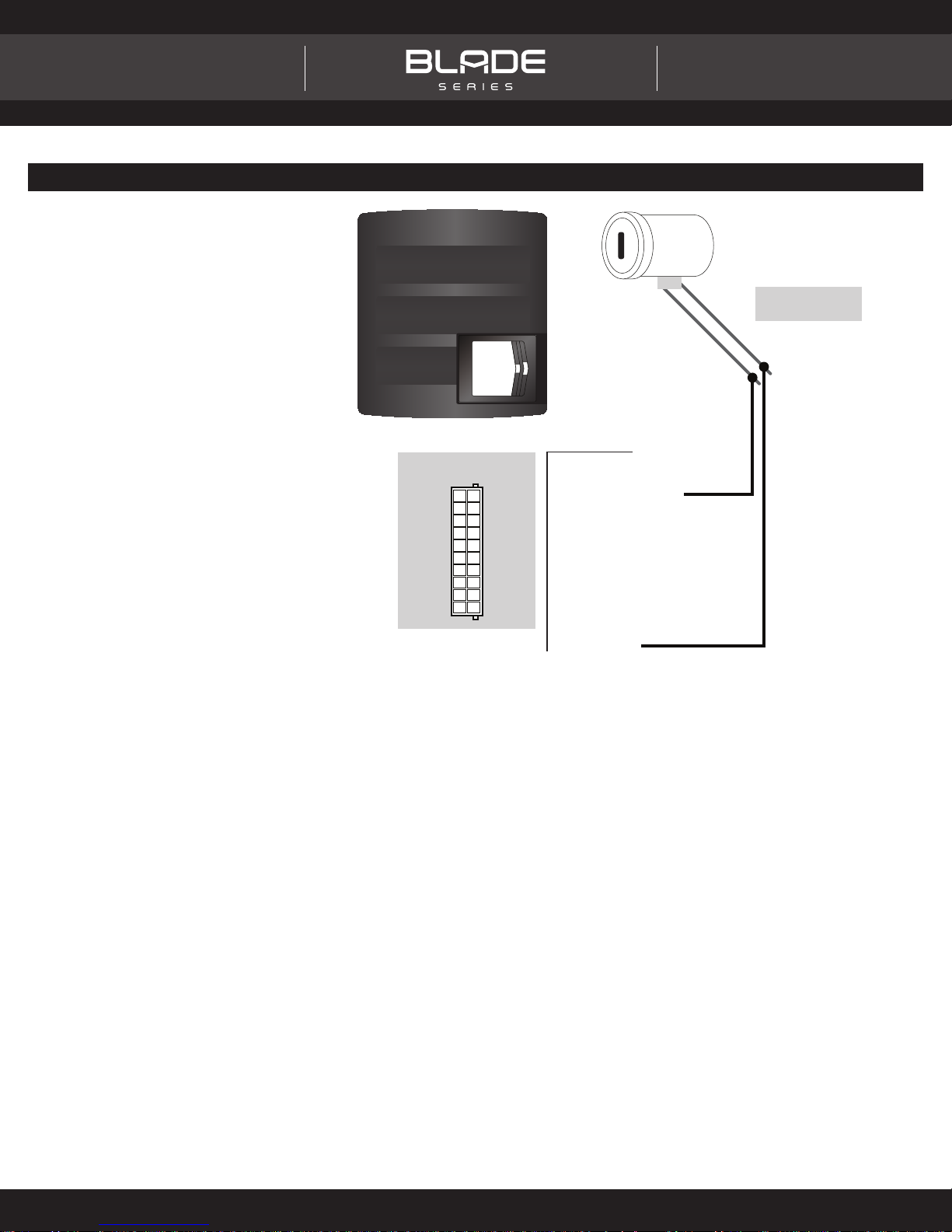
TYPE 1 - WIRING DIAGRAM
REMOTE STARTER
VATS
*BLADE CONNECTOR
EXACT PIN-OUT
10
20
WHITE/BLACKWHITE/RED
09
19
NO WIREWHITE
08
18
PINKPINK/BLACK
07
17
BLACKNO WIRE
06
16
BROWN/YELLOWBROWN/RED
05
15
ORANGE/WHITEORANGE/BLACK
04
NO WIREORANGE
14
03
13
BLUE/RED
GRAY/RED GRAY/YELLOW
BLUE/YELLOW
02
12
YELLOWGREEN/RED
01
11
WHITE/BLACK (NC)
WHITE/BLACK (NC)
WHITE/RED (NC)
WHITE/RED (NC)
WHITE (NC)
WHITE (NC)
YELLOW - VATS (1 TO 5 VOLTS)YELLOW - VATS (1 TO 5 VOLTS)
BROWN/RED (NC)BROWN/RED (NC)
BROWN/YELLOW (NC)
BROWN/YELLOW (NC)
ORANGE/BLACK (NC)
ORANGE/BLACK (NC)
ORANGE/WHITE (NC)
ORANGE/WHITE (NC)
ORANGE (NC)
ORANGE (NC)
PINK/BLACK (NC)
PINK/BLACK (NC)
PINK (NC)
PINK (NC)
BLUE/RED (NC)
BLUE/RED (NC)
BLUE/YELLOW (NC)
BLUE/YELLOW (NC)
GREEN/RED (NC)GREEN/RED (NC)
GRAY/RED (NC)
GRAY/RED (NC)
GRAY/YELLOW (NC)
GRAY/YELLOW (NC)
BLACK - GROUND (-)BLACK - GROUND (-)
VATS GROUND
VATS (1 TO 5V)
VATS WIRES ARE
LOCATED IN AN ORANGE
OR GRAY HARNESS
Automotive Data Solutions Inc. © 2015
INSTALL GUIDE
TRANSPONDER BYPASS
GM
U.S. Patent No. 8,856,780
Page 4 of 6 OL-BLADE-AL(TB)-PL1-EN 20150714
Doc. No.: ##22390##
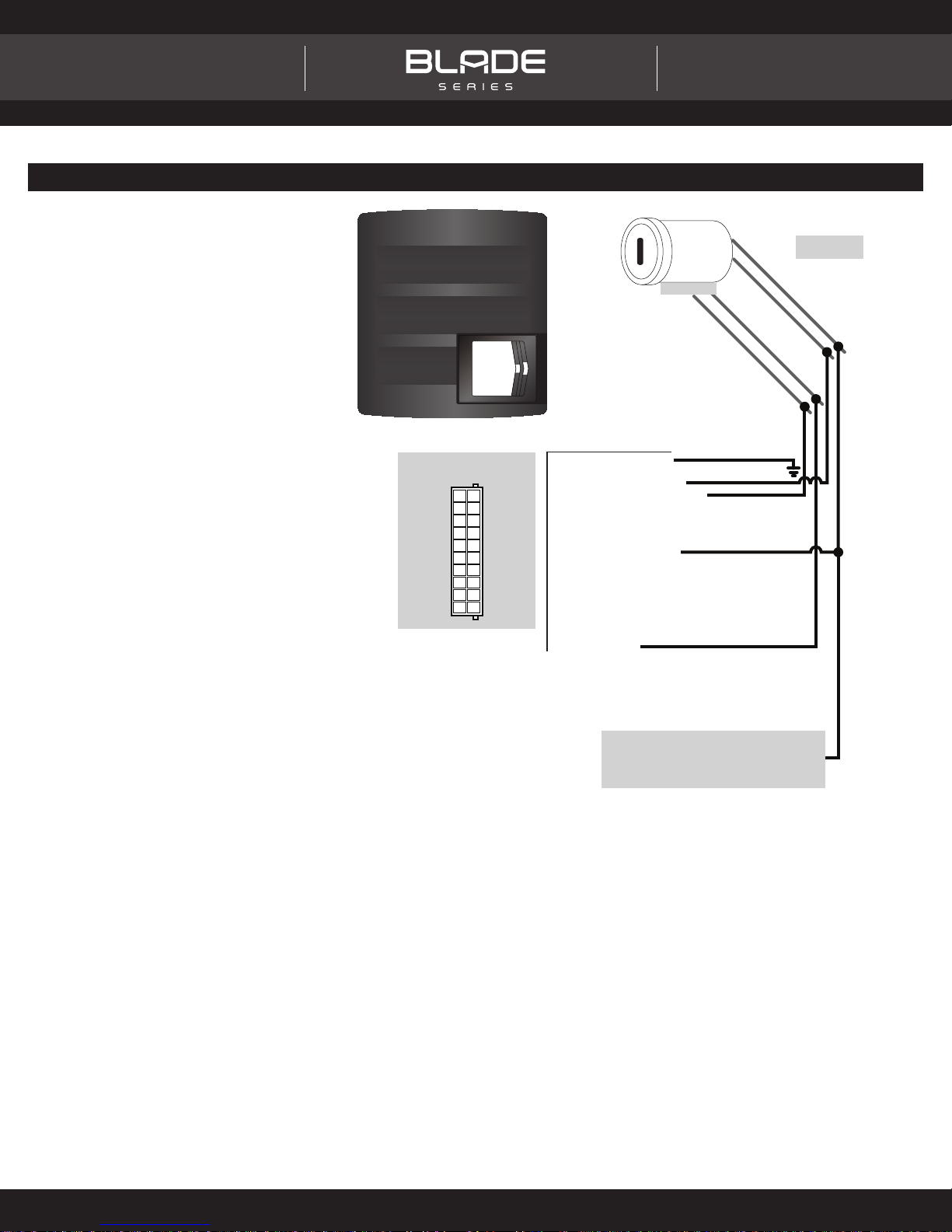
TYPE 2 - WIRING DIAGRAM
REMOTE STARTER
*BLADE CONNECTOR
EXACT PIN-OUT
10
20
WHITE/BLACKWHITE/RED
09
19
NO WIREWHITE
08
18
PINKPINK/BLACK
07
17
BLACKNO WIRE
06
16
BROWN/YELLOWBROWN/RED
05
15
ORANGE/WHITEORANGE/BLACK
04
NO WIREORANGE
14
03
13
BLUE/RED
GRAY/RED GRAY/YELLOW
BLUE/YELLOW
02
12
YELLOWGREEN/RED
01
11
PASSLOCK 1
WHITE/BLACK - GROUND (-)
WHITE/BLACK - GROUND (-)
WHITE/RED (NC)
WHITE/RED (NC)
WHITE - BULBTEST (-) OUTPUT
WHITE - BULBTEST (-) OUTPUT
YELLOW - PASSLOCK (1 TO 4 VOLTS)
YELLOW - PASSLOCK (1 TO 4 VOLTS)
BROWN/RED (NC)BROWN/RED (NC)
BROWN/YELLOW (NC)
BROWN/YELLOW (NC)
ORANGE/BLACK (NC)
ORANGE/BLACK (NC)
ORANGE/WHITE (NC)
ORANGE/WHITE (NC)
ORANGE - STARTER (+) INPUT
ORANGE - STARTER (+) INPUT
PINK/BLACK (NC)
PINK/BLACK (NC)
PINK (NC)
PINK (NC)
BLUE/RED (NC)BLUE/RED (NC)
BLUE/YELLOW (NC)
BLUE/YELLOW (NC)
GREEN/RED (NC)
GREEN/RED (NC)
GRAY/RED (NC)
GRAY/RED (NC)
GRAY/YELLOW (NC)
GRAY/YELLOW (NC)
BLACK - GROUND (-)
BLACK - GROUND (-)
YELLOW - STARTER
BLACK - BULBTEST
BLACK - GROUND
YELLOW - (1 TO 4V)
MAIN IGNITION
HARNESS
WARNING: MANUAL TRANSMISSION ONLY
MAKE SURE THE REMOTE STARTER (+) START WIRE
IS CONNECTED TO THE IGNITION HARNESS WITH
THIS STARTER INPUT (NOT ON THE OTHER SIDE
OF THE CLUTCH PEDAL SWITCH).
Automotive Data Solutions Inc. © 2015
INSTALL GUIDE
TRANSPONDER BYPASS
GM
U.S. Patent No. 8,856,780
Page 5 of 6 OL-BLADE-AL(TB)-PL1-EN 20150714
Doc. No.: ##22390##
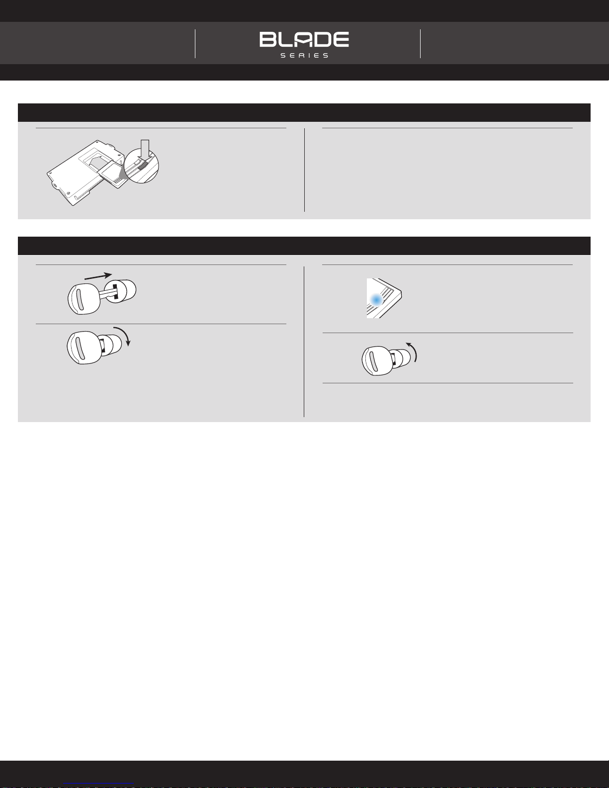
CARTRIDGE INSTALLATION
1
Slide cartridge into unit. Notice
button under LED.
2
Ready for Module Programming
Procedure.
MODULE PROGRAMMING PROCEDURE
Wait, LED will turn solid BLUE
for 2 seconds.
(If after 5 seconds the LED did
not turn solid BLUE, press on
the programming button once.)
Turn key to OFF position.
1
2
ON
Insert key into ignition.
3
Turn key to ON position.
OFF
4
5
Module Programming
Procedure completed.
Automotive Data Solutions Inc. © 2015
XX-XX
PAGE X-X
NOTICE
PATENT
PAGE X-X
INSTALL GUIDE
U.S. Patent No. 8,856,780
TRANSPONDER BYPASS
GM
Page 6 of 6 OL-BLADE-AL(TB)-PL1-EN 20150714
IDENTIFY VEHICLE YEAR
Locate the Vehicle Identifi cation Number (VIN), identify the 10th
1
character then match it to its corresponding year.
Æ
4 Y 1 N53 A 5 T A L 8 D 5 R 0 X
Æ
A
1980
B
1981
C
1982
D
1983
E
1984
F
1985
G
1986
H
1987
J
1988
K
1989
L
M
N
P
R
S
T
V
W
X
Doc. No.: ##22390##
1990
1991
1992
1993
1994
1995
1996
1997
1998
1999
Y
1
2
3
4
5
6
7
8
9
2000
2001
2002
2003
2004
2005
2006
2007
2008
2009
A
2010
B
2011
C
2012
D
2013
E
2014
F
2015
G
2016
H
2017
J
2018
K
2019
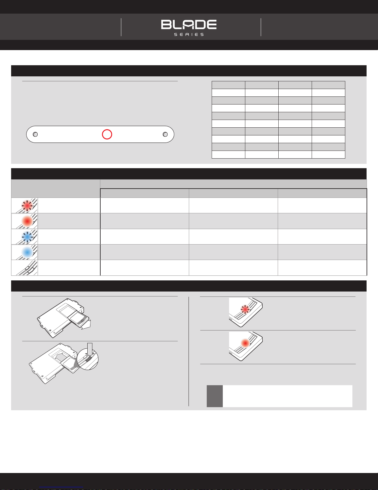
MODULE DIAGNOSTICS
LED STATUS
Flashing RED
Solid RED Waiting for more vehicle information Incorrectly programmed
Flashing BLUE
DURING PROGRAMMING DURING REMOTE START WITH IGNITION OFF
Missing/wrong information from
fi rmware or vehicle
Additional steps required to complete
programming
Incorrectly programmed Incorrectly programmed or connected
Correctly programmed and
operational
DIAGNOSTICS
Not programmed waiting for more
vehicle information
False ground when running status
from remote starter
Solid BLUE then OFF Correctly programmed Reset in progress Reset in progress
OFF No activity or already programmed
Invalid ground when running status
from remote starter
At rest and ready for a remote start
sequence
FACTORY RESET PROCEDURE
1
2
DISCONNECT cartridge from
remote starter.
PRESS AND HOLD programming
button while re-connecting
cartridge to remote starter.
3
4
5
Failure to follow procedure may result with a DTC or a
CHECK ENGINE error message.
!
LED will fl ash red. Immediately
RELEASE programming button.
LED will turn solid red for 2
seconds.
RESET COMPLETED.
RECONNECT all connectors.
Repeat programming procedure.
This product is protected by one or more of the following patents: U.S. LETTERS PATENT NO. 5,719,551; 6,011,460; 6,243,004; 6,249,216; 6,275,147; 6,297,731; 6,346,876; 6,392,534; 6,529,124; 6,696,927; 6,756,885; 6,756,886; 6,771,167; 6,812,829; 6,924,750;
7,010,402; 7,031,826; 7,046,126; 7,061,137; 7,068,153; 7,015,830; 7,205,679; 7,224,083; 7,369,936; 7,378,945; 7,489,233; 7,501,937; CANADIAN PATENT NO. 2,320,248; 2,415,023; 2,426,670; 2,414,991; 2,415,011; 2,415,027; 2,415,038; 2,415,041; 2,502,893; 2,451,490;
2,452,296; 2,451,487; EUROPEAN PATENT NO. 1,053,128; DE 69807-941T2; U.S. 20020145535; 20060129282; 20060129284; 20040017284; 20080030316; 20090079552; EP1500565; 1538038; 1538037;
Automotive Data Solutions Inc. © 2015
 Loading...