


FLEXIBLE GAS PIPING
FLEXIBLE GAS PIPING
DESIGN GUIDE
DESIGN GUIDE
and
and
INSTALLATION INSTRUCTIONS
INSTALLATION INSTRUCTIONS
December 2005
December 2005
®
RESIDENTIAL • COMMERCIAL • INDUSTRIAL
RESIDENTIAL • COMMERCIAL • INDUSTRIAL
FGP-001, Rev. 12-05
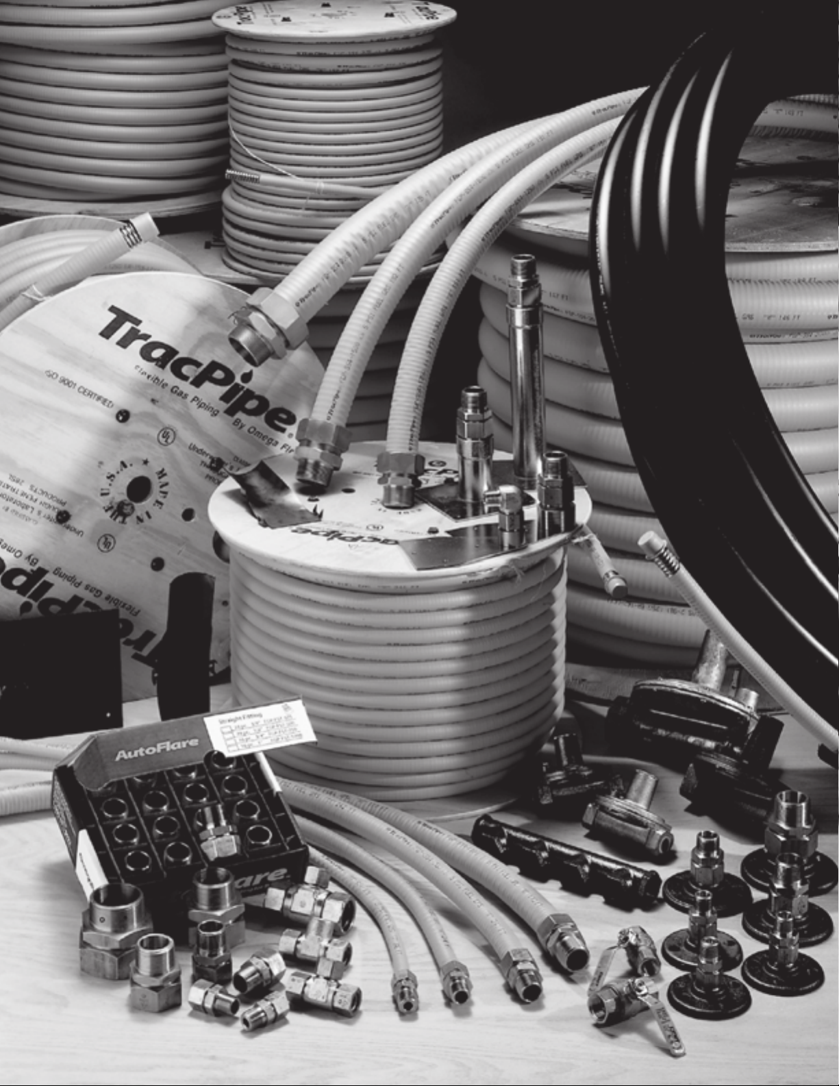

TABLE OF CONTENTS
Chapter 1 Introduction
1.0 User Warnings . . . . . . . . . . . . . . . . . . . . . . . . . . . . . . . . . . . . . . . . . . . . . . . . . . . . .3
1.1 Listing of Applicable Codes and Standards . . . . . . . . . . . . . . . . . . . . . . 4
TracPipe Specification Data Sheet . . . . . . . . . . . . . . . . . . . . . . . . . . . . . 5
Chapter 2 Description of System and Components
2.0 Tubing . . . . . . . . . . . . . . . . . . . . . . . . . . . . . . . . . . . . . . . . . . . . . . . . . . . 6
Fittings . . . . . . . . . . . . . . . . . . . . . . . . . . . . . . . . . . . . . . . . . . . . . . . . . . . . . . .6
Accessories . . . . . . . . . . . . . . . . . . . . . . . . . . . . . . . . . . . . . . . . . . . . . . . . . . . .6
Manifolds . . . . . . . . . . . . . . . . . . . . . . . . . . . . . . . . . . . . . . . . . . . . . . . . . . . . . .6
Pressure Regulators . . . . . . . . . . . . . . . . . . . . . . . . . . . . . . . . . . . . . . . . . . 6
Protection Devices . . . . . . . . . . . . . . . . . . . . . . . . . . . . . . . . . . . . . . . . . . . . . . .6
Shut-off Valves . . . . . . . . . . . . . . . . . . . . . . . . . . . . . . . . . . . . . . . . . . . . . . . .7
2.1 Material Use and Limitations . . . . . . . . . . . . . . . . . . . . . . . . . . . . . . . . . 7
2.2 System Components . . . . . . . . . . . . . . . . . . . . . . . . . . . . . . . . . . . . . . . 9
TracPipe Flexible Gas Piping . . . . . . . . . . . . . . . . . . . . . . . . . . . . . . . . . 9
AutoFlare Fittings . . . . . . . . . . . . . . . . . . . . . . . . . . . . . . . . . . . . . . . . . 10
TracPipe Accessories . . . . . . . . . . . . . . . . . . . . . . . . . . . . . . . . . . . . . . . . . 11
Chapter 3 System Configurations and Sizing
3.1 System Configurations . . . . . . . . . . . . . . . . . . . . . . . . . . . . . . . . . . . . . 13
3.1A Series and Parallel Low-pressure Systems . . . . . . . . . . . . . . . . . . . . . 13
3.1B Dual Presure Systems . . . . . . . . . . . . . . . . . . . . . . . . . . . . . . . . . . . . . . . . .13
3.1C System Design . . . . . . . . . . . . . . . . . . . . . . . . . . . . . . . . . . . . . . . . . . . . . . .14
3.1D System Pressure Choices . . . . . . . . . . . . . . . . . . . . . . . . . . . . . . . . . . . . . 14
3.2 Sizing Methods and Examples . . . . . . . . . . . . . . . . . . . . . . . . . . . . . . . 15
3.2A Use of Sizing Tables . . . . . . . . . . . . . . . . . . . . . . . . . . . . . . . . . . . . . . . 15
3.2B Sizing Examples . . . . . . . . . . . . . . . . . . . . . . . . . . . . . . . . . . . . . . . . . . 15
Low-pressure Systems . . . . . . . . . . . . . . . . . . . . . . . . . . . . . . . . . . . . . 15
Elevated Pressure Systems . . . . . . . . . . . . . . . . . . . . . . . . . . . . . . . . . . . 17
Medium Pressure Systems . . . . . . . . . . . . . . . . . . . . . . . . . . . . . . . . . . . 17
3.2C Sizing Hybrid Systems (Combination Steel/TracPipe Systems) . . . . . . 19
3.2D Alternate Sizing Method (Sum of Pressure Loss Calculations) . . . . . . . 21
3.3 Gasbreaker Excess Flow Devices for CSST and
Steel Pipe Gas Systems . . . . . . . . . . . . . . . . . . . . . . . . . . . . . . . . . . . . 25
3.4 Sizing Instructions for Gasbreaker Devices Used with
CSST/TracPipe Systems . . . . . . . . . . . . . . . . . . . . . . . . . . . . . . . . . . . . . . . 26
3.4A Meter Devices (Series GB-300, GB-400, GB-600) . . . . . . . . . . . . . . . . 26
3.4B Appliance Devices (Series GB-090, GB-120, GB-150) . . . . . . . . . . . . . 26
3.4C Sizing Instructions for Gasbreaker Devices with Steel Pipe Systems . . . . . 26
Chapter 4 Installation Practices
4.1 General Installation Practices . . . . . . . . . . . . . . . . . . . . . . . . . . . . . . . . 31
Minimum Bend Radius . . . . . . . . . . . . . . . . . . . . . . . . . . . . . . . . . . . . . 31
Debris Protection . . . . . . . . . . . . . . . . . . . . . . . . . . . . . . . . . . . . . . . . . 31
Support- Vertical Runs/ Horizontal Runs . . . . . . . . . . . . . . . . . . . . . . . 32
4.2 Fitting Assembly . . . . . . . . . . . . . . . . . . . . . . . . . . . . . . . . . . . . . . . . . . 33
Tubing Cutting/End Preparation . . . . . . . . . . . . . . . . . . . . . . . . . . . . . . 33
Assembly Procedure . . . . . . . . . . . . . . . . . . . . . . . . . . . . . . . . . . . . . . . 34
Minimum Tightening Torque . . . . . . . . . . . . . . . . . . . . . . . . . . . . . . . . . 34
Re-assembly Procedure . . . . . . . . . . . . . . . . . . . . . . . . . . . . . . . . . . . . 34
4.2A Trouble Shooting Fitting Connections . . . . . . . . . . . . . . . . . . . . . . . . . . 35
4.3 Routing . . . . . . . . . . . . . . . . . . . . . . . . . . . . . . . . . . . . . . . . . . . . . . . . . 36
Clearance Holes and Notching . . . . . . . . . . . . . . . . . . . . . . . . . . . . . . . . 36
4.3A Concealed Locations for Fittings . . . . . . . . . . . . . . . . . . . . . . . . . . . . . 36
4.3B Outdoor Installation Issues . . . . . . . . . . . . . . . . . . . . . . . . . . . . . . . . . . 37
4.4 Protection . . . . . . . . . . . . . . . . . . . . . . . . . . . . . . . . . . . . . . . . . . . . . . . 38
1

4.4A Striker Plate Requirements . . . . . . . . . . . . . . . . . . . . . . . . . . . . . . . . . . 38
Spiral Metal Hose Requirements . . . . . . . . . . . . . . . . . . . . . . . . . . . . . 39
Thru-penetration Fire Stop UL Classifications . . . . . . . . . . . . . . . . . . . 40
4.5 Meter Connections . . . . . . . . . . . . . . . . . . . . . . . . . . . . . . . . . . . . . . . . 41
Termination Mounts/Meter Mounts . . . . . . . . . . . . . . . . . . . . . . . . . . . . . 41
Direct Connection . . . . . . . . . . . . . . . . . . . . . . . . . . . . . . . . . . . . . . . . . 41
4.6 Appliance Connections . . . . . . . . . . . . . . . . . . . . . . . . . . . . . . . . . . . . . . . . 42
4.6.1 Moveable Appliances . . . . . . . . . . . . . . . . . . . . . . . . . . . . . . . . . . . . . . . 42
Termination Fittings with Appliance Connectors . . . . . . . . . . . . . . . . . . 42
4.6.2 Fixed Appliance Connections . . . . . . . . . . . . . . . . . . . . . . . . . . . . . . . . 42
Direct Connection . . . . . . . . . . . . . . . . . . . . . . . . . . . . . . . . . . . . . . . . . 42
4.6A Pad Mounted, Roof Top Equipment . . . . . . . . . . . . . . . . . . . . . . . . . . . 45
4.6B Outdoor Appliances . . . . . . . . . . . . . . . . . . . . . . . . . . . . . . . . . . . . . . . 46
4.6C Fireplace Installations . . . . . . . . . . . . . . . . . . . . . . . . . . . . . . . . . . . . . . 47
4.7 Manifold Stations . . . . . . . . . . . . . . . . . . . . . . . . . . . . . . . . . . . . . . . . . 48
Allowable Locations . . . . . . . . . . . . . . . . . . . . . . . . . . . . . . . . . . . . . . . 48
4.8 Pressure Regulators . . . . . . . . . . . . . . . . . . . . . . . . . . . . . . . . . . . . . . . 49
Installation Requirements . . . . . . . . . . . . . . . . . . . . . . . . . . . . . . . . . . . 49
Vent Limiter Option . . . . . . . . . . . . . . . . . . . . . . . . . . . . . . . . . . . . . . . . 49
Vent Line and Sizing Requirements . . . . . . . . . . . . . . . . . . . . . . . . . . . . 49
4.8A Adjustments . . . . . . . . . . . . . . . . . . . . . . . . . . . . . . . . . . . . . . . . . . . . . 49
4.8B Regulator Capacity and Pressure Drop . . . . . . . . . . . . . . . . . . . . . . . . . 50
4.8C Over-Pressurization Protection . . . . . . . . . . . . . . . . . . . . . . . . . . . . . . . 51
4.9 Underground Installations . . . . . . . . . . . . . . . . . . . . . . . . . . . . . . . . . . . 52
4.9A Guidelines for Underground Installations . . . . . . . . . . . . . . . . . . . . . . . 52
4.9B TracPipe PS Fitting Attachment Instructions . . . . . . . . . . . . . . . . . . . . 54
4.9C Underground PS with Flexible Poly Tubing . . . . . . . . . . . . . . . . . . . . . . 55
4.9D TracPipe PS-II . . . . . . . . . . . . . . . . . . . . . . . . . . . . . . . . . . . . . . . . . . . . 57
4.9E TracPipe PS-II Fitting Attachment Instructions . . . . . . . . . . . . . . . . . . . 58
4.10 Electrical Bonding/Grounding . . . . . . . . . . . . . . . . . . . . . . . . . . . . . . . . . 60
4.10A TracPipe CounterStrike CSST Installations . . . . . . . . . . . . . . . . . . . . . 61
Chapter 5 Inspection Repair and Replacement
5.1 Minimum Inspection Requirements (Checklist) . . . . . . . . . . . . . . . . . . . 63
5.2 Repair/Replacement of Damaged Tubing . . . . . . . . . . . . . . . . . . . . . . . . 64
Chapter 6 Pressure/Leakage Testing
6.0 Pressure Test Procedure . . . . . . . . . . . . . . . . . . . . . . . . . . . . . . . . . . . . . . . 65
6.1 Pressure Test for Elevated Pressure Systems . . . . . . . . . . . . . . . . . . . . . 65
6.1A Appliance Connection Leakage Check Procedure . . . . . . . . . . . . . . . . . 66
6.1B Regulator Performance . . . . . . . . . . . . . . . . . . . . . . . . . . . . . . . . . . . . . 66
Chapter 7 Capacity Tables
7 in / 0.5 in WC Drop . . . . . . . . . . . . . . . . . . . . . . . . . . . . . . . . . . . . . . . . . . . . . . . . . 68
8 in / 2 in WC Drop . . . . . . . . . . . . . . . . . . . . . . . . . . . . . . . . . . . . . . . . . . . . . . 69
11 in / 5 in WC Drop . . . . . . . . . . . . . . . . . . . . . . . . . . . . . . . . . . . . . . . . . . . . . 70
2 PSI / 1 PSI Drop . . . . . . . . . . . . . . . . . . . . . . . . . . . . . . . . . . . . . . . . . . . . . . 71
5 PSI / 3.5 PSI Drop . . . . . . . . . . . . . . . . . . . . . . . . . . . . . . . . . . . . . . . . . . . . . 72
11 in / 0.5 in WC Drop (LP only) . . . . . . . . . . . . . . . . . . . . . . . . . . . . . . . . . . . . 72
12-14 in / 2.5 in Drop (LP only) . . . . . . . . . . . . . . . . . . . . . . . . . . . . . . . . . . . . 73
2 PSI / 1.5 PSI Drop (LP only) . . . . . . . . . . . . . . . . . . . . . . . . . . . . . . . . . . . . . 74
7.1 Table PD.1 Pressure Drop per foot for TracPipe (Natural Gas) . . . . . . 75
7.2 Steel Pipe . . . . . . . . . . . . . . . . . . . . . . . . . . . . . . . . . . . . . . . . . . . . . . . 80
7.2A Pressure Drop per 100 foot of Steel Pipe . . . . . . . . . . . . . . . . . . . . . . . . . 81
Chapter 8
Definitions . . . . . . . . . . . . . . . . . . . . . . . . . . . . . . . . . . . . . . . . . . . . . . . . . . . . . 83
Appendix A UL Classification . . . . . . . . . . . . . . . . . . . . . . . . . . . . . . . . . . . . . . . . . 85
Appendix B Manufactured Housing Guidelines . . . . . . . . . . . . . . . . . . . . . . . . . . . 88
2

CHAPTER 1
INTRODUCTION
!
WARNINGS
SECTION 1.0 — USER WARNINGS
The TracPipe®gas piping material (CSSTCorrugated Stainless Steel Tubing ) must
only be installed by a qualified person who
has been trained or otherwise qualified
through the TracPipe Gas Piping
Installation Program. Any installer must also
meet qualifications in accordance with state
and/or local requirements as established by
the administrative authority which enforces
the plumbing or mechanical code where the
gas piping is installed.
This document provides general instructions for the
design and installation of fuel gas piping systems
using gas piping material CSST . The guide must be
used in conjunction with state and local building
codes. Local codes will take precedence in
the event of a conflict between this guide
and the local code. In the absence of local
codes, installation must be in accordance with the
current edition of National Fuel Gas Code, ANSI
Sound engineering principles and practices
must be exercised for the proper design of
fuel gas piping systems, in addition to compliance with local codes. The installation
instructions and procedures contained in this
Design Guide must be strictly followed in
order to provide a safe and effective fuel gas
piping system or system modification. All
installations must pass customary inspections
by the local official having authority prior to
having the gas service turned on. All requirements of the local natural gas utility or
propane supplier must also be met.
Only the components provided or specified
by OMEGAFLEX as part of the approved
piping system are to be used in the installation.
The use of
TracPipe tubing or fittings
with tubing or fittings from other flexible gas piping manufacturers is strictly prohibited and may result in serious
bodily injury or property damage.
Z223.1/NFP A 54, the National Standard of Canada,
Natural Gas and Propane Installation Code, CSA
B149.1, the International Fuel Gas Code, the
Federal Manufactured Home Construction
and Safety Standards, ICC/ANSI 2.0 or the
Standard on Manufactured Housing, NFPA
501, as applicable
S
I
F
S
I
E
A
D
L
C
U
L
OMEGAFLEX
®
451 Creamery Way
Exton, PA 19341-2509
610-524-7272 Fax: 610-524-7282
WARNING !
If this system is used or installed improperly,
fire, explosion or asphyxiation may result.
The installation instructions and applicable
local codes must be strictly followed.
1-800-671-8622 www.omegaflex.com
© Copyright OmegaFlex Inc. 1997, 1998, 2001, 2002,
2003, 2004, 2005
3

SECTION 1.1 — APPLICABLE
CODES AND STANDARDS
REGIONAL /MODEL CODES LISTING CSST
AS AN ACCEPTABLE GAS PIPING
MATERIAL AS OF JULY 2005:
a. ANSI/IAS LC-1
b. CANADA-CSA B149.1 Natural Gas
and Propane Installation Code
c. NFPA 54/ANSI Z 223.1 National Fuel
Gas Code
d. ICBO-Uniform Mechanical Code
e. BOCA-National Mechanical Code
f. CABO-1 and 2 Family Dwelling Code
g. SBCCI-Standard Gas Code
h. ICC-International Mechanical Code
i. IAPMO Listing FILE 3682
j. IAPMO Listing FILE 4665 TracPipe
PS-II
• CSA 6.26 Standard
k. ICBO Evaluation Services ER-5412.
l. Factory Mutual “Flexible Piping
Systems for Flammable Gases.”
m. California Mechanical and Plumbing
Codes
n. ICC-International Fuel Gas Code
o. NFPA 58 LP-Gas Code
p. UPC-Uniform Plumbing Code 2003
q. UL Through Penetration Firestop
Systems Classified (see Appendix A)
r. Tested to Code Requirements per
ASTM E84 (UL 723)
This Design and Installation Guide has been
written in accordance with the most current
edition of ANSI LC1 CSA 6.26, Fuel Gas
Piping Systems using Corrugated Stainless
Steel Tubing (CSST).
WHILE EVERY EFFORT HAS BEEN MADE TO PREPARE THIS DOCUMENT
IN ACCORDANCE WITH THE REGIONAL MODEL CODES IN EFFECT AT
ITS PRINTING, OMEGAFLEX CANNOT GUARANTEE THAT THE LOCAL ADMINISTRATIVE AUTHORITY WILL ACCEPT THE MOST RECENT VERSION OF
THESE CODES.
THE INSTALLER IS ULTIMATELY RESPONSIBLE TO DETERMINE SUITABILITY
AND ACCEPTANCE OF ANY BUILDING COMPONENT, INCLUDING GAS
PIPING. OMEGAFLEX ASSUMES NO RESPONSIBILITY FOR MATERIALS OR
LABOR FOR INSTALLATIONS MADE WITHOUT PRIOR DETERMINATION OF
LOCAL CODE AUTHORITY ACCEPTANCE.
4
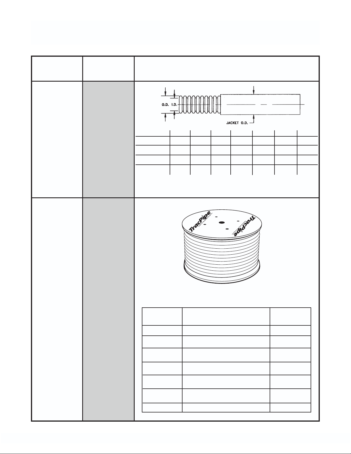
TracPipe
®
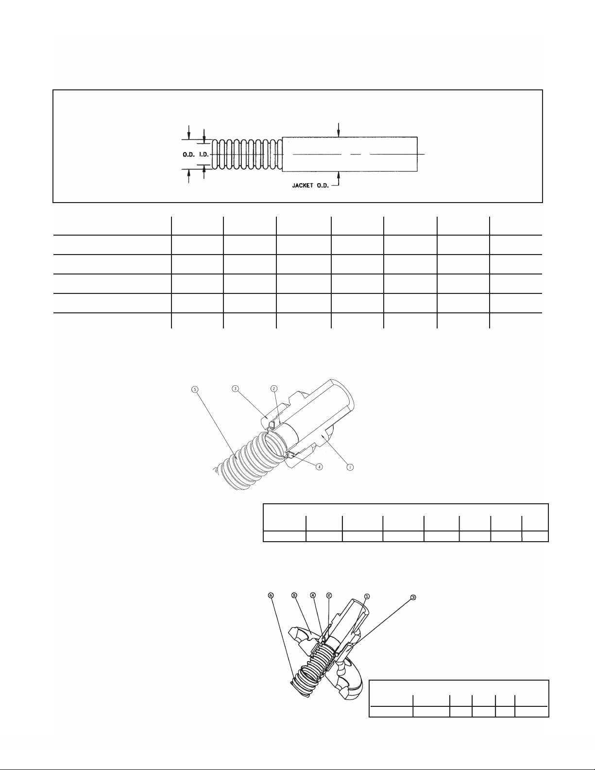
SPECIFICATION DATA SHEET
FGP-SS4-CHART
TracPipe®part no.
FGP-SS4-375 FGP-SS4-500 FGP-SS4-750 FGP-SS4-1000 FGP-SS4-1250 FGP-SS4-1500 FGP-SS4-2000
Size (inch) 3/8" 1/2" 3/4" 1" 1-1/4" 1-1/2" 2"
EHD (AGA size) 15 19 25 31 37 46 62
Jacket O.D. (max.) .668 .868 1.108 1.383 1.665 1.920 2.590
Inside Diameter (nom) .440 .597 .820 1.040 1.290 1.525 2.060
Wall Thickness (in.) .01 .01 .01 .01 .012 .012 .012
*EHD (Effective Hydraulic Diameter) A relative measure of Flow Capacity; This number is used to compare individual sizes between different manufacturers. The
higher the EHD number the greater flow capacity of the piping.
STRAIGHT AUTO-FLARE FITTINGS
1. ADAPTER – Brass
2. INSERT – Stainless Steel
3. NUT—Brass
4. SPLIT-RINGS – Brass or
Stainless Steel
5. FLEXIBLE PIPE – Stainless Steel
Tube size 3/8" 1/2" 3/4" 1" 1-1/4" 1-1/2" 2"
NPT Thread 1/2"or 3/8" 1/2"or 3/4" 3/4"or 1/2" 1"or 3/4" 1-1/4" 1-1/2" 2"
AVAILABLE IN SIZES
FLANGE MOUNT AUTO-FLARE FITTINGS
1. ADAPTER – Brass
2. INSERT – Stainless Steel
3. FLANGE NUT – Brass
4. SPLIT-RINGS – Brass or
Stainless Steel
5. FLANGE – Malleable Iron/Brass
6. FLEXIBLE PIPE – Stainless Steel
CONSULT FACTORY FOR OTHER TERMINATION METHODS
5
AVAILABLE IN SIZES
Tube Size 3/8" 1/2" 3/4" 1" 1-1/4"
NPT Thread 1/2"or 3/8" 1/2" 3/4" 1" 1-1/4"
CHAPTER 2
DESCRIPTION of SYSTEM and COMPONENTS
SECTION 2.0 — TracPipe
FLEXIBLE GAS PIPING MATERIAL
DESCRIPTION
1. TUBING
The TracPipe fuel gas piping system con-
sists of corrugated, semi-rigid stainless
steel tubing with brass mechanical attachment fittings terminating in NPT pipe fittings for easy attachment to traditional
black iron pipe systems and direct connections to gas appliances.
Tubing is available in sizes 3/8 inch, 1/2 inch
3/4 inch, 1 inch, 1-1/4 inch, 1-1/2 inch,and 2
inch.
The 300 series stainless steel tubing is jacketed, with a non-metallic cover which provides ease of running through joists, studs,
and other building components. The jacket is
marked at
one foot
intervals
with the
amount of
tubing left
on the reel,
for quick
measurement.
2. FITTINGS
Straight NPT pipe fittings are standard and are
available in sizes shown above to fit all tubing.
Additional fittings include termination mount
and flange-mount straight and 90 degree
elbow fittings for termination of gas lines near
movable appliances; and meter termination
accessories for support of TracPipe at utility
meter sets on building exteriors and roof penetrations. Tee fittings are available for addition of branch lines into tubing runs; reducer
tees are available in popular sizes and pipe
outlet tees terminate in pipe threads on the
outlet leg for size changes utilizing available
black iron reducer fittings.
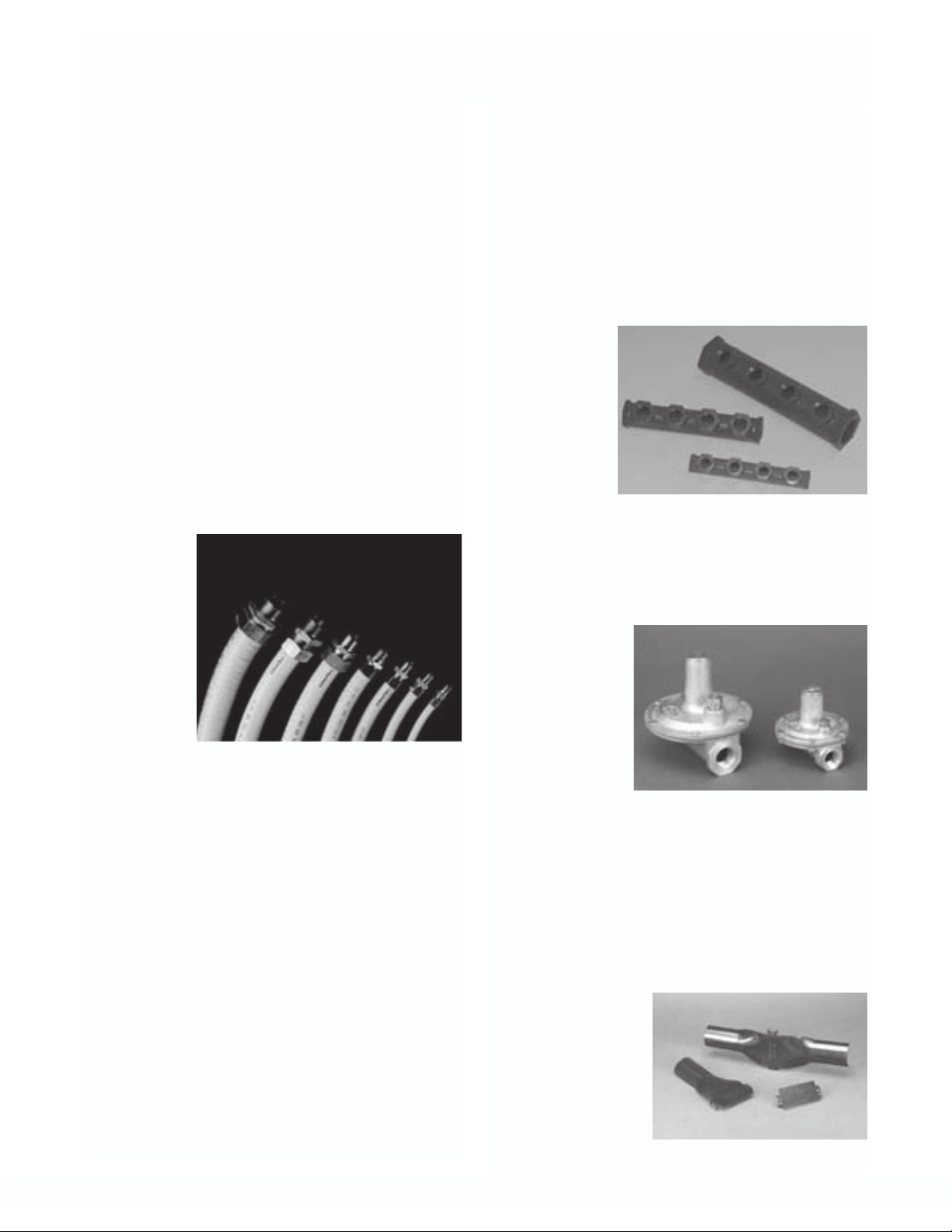
3. ACCESSORIES
Accessories are available for expansion of
the flexible piping material and additions to
existing fuel gas piping systems. These
accessories include:
A. Manifolds — allow parallel installations
with “home runs” to each appliance.
1/2 inch female NPT outlets and 3/4 inch
and
1/2 inch
female
NPT
inlets.
Large size
manifolds
are also
available
for use with commercial size TracPipe.
B. Pressure Regulators: pounds to inches -
for use in elevated pressure system
installations (over 14 inches water column
- one half
psi) to
reduce
pressure
to standard low
pressure
for appliances.
Available regulators include 1/2 and 3/4
inch sizes for natural and propane use
and 1-1/4 inch size for natural gas.
Regulators include approved vent limiters
except 1-1/4" size.
C. Protection Devices-for use where flexible
piping passes through studs, joists and
other building
materials and
is restricted
from moving
to avoid nails,
screws and
other puncture threats.
6
There are four striker plate configurations made from stamped steel and
specially hardened to resist penetration
from screws and pneumatic nail guns.
These are quarter-striker, half striker fullstriker and 6" X 17" flat plate striker. Spiral
wound galvanized steel “floppy” conduit is
available for use as additional protection.
Some of the special usage features of
TracPipe gas piping are outlined below:
1. Flexible gas piping is used to provide safe,
efficient, timely installation of fuel gas piping within buildings, residential, commercial, and industrial, or for outdoor connections to appliances that are attached or in
close proximity to the building.
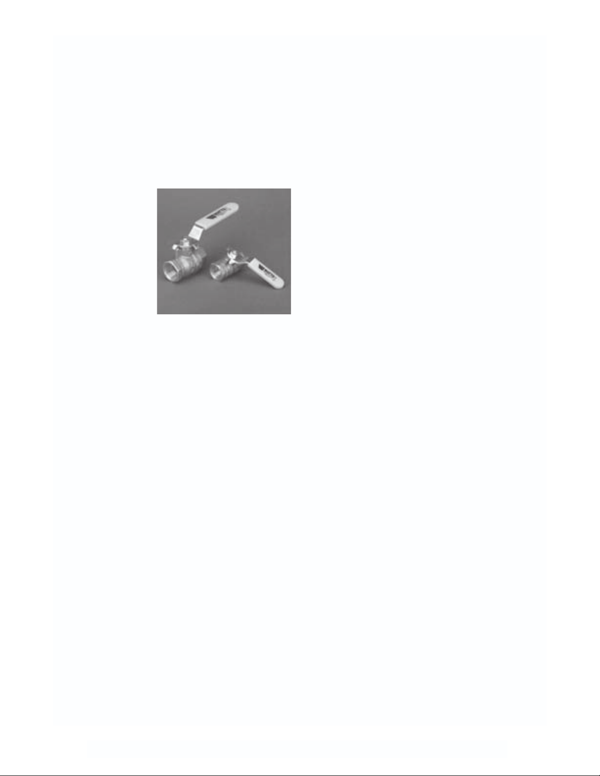
D. Shut-off Valves-for use in elevated pres-
sure installations: 2 psi up to 5 psi.
(Standard
gas-cocks
should be
used at appliance stub
outs and other
low pressure
areas of the
piping system.) Brass
lever-handle ball valves supplied by
OmegaFlex are rated for 5 psi use and
are available in 1/2 inch and 3/4 inch sizes.
SECTION 2.1 — MATERIAL USE
AND LIMITATIONS
This Design and Installation Guide has
been written in accordance with the most
current edition of ANSI LC 1 CSA 6.26,
FUEL GAS PIPING SYSTEMS USING CORRUGATED STAINLESS STEEL TUBING
(CSST).
This Design Guide is intended to aid the professional gas pipe installer in the design,
installation and testing of flexible fuel gas piping systems for residential, commercial and
industrial buildings. It is not possible for this
guide to anticipate every variation in construction style, building configuration, appliance requirement, or local restriction. This
document will not therefore cover every application. The user should either exercise his
own engineering judgment on system design
and installation, or seek technical input from
other qualified sources. Additional information pertaining to gas piping systems is available from your local gas utility or propane
supplier.
2. Flexible gas piping can be routed in most
locations where traditional gas piping
materials are installed: inside hollow wall
cavities, along or through floor joists in
basements, on top of the joists in attics,
on roof tops or along soffits or in chases
outside of buildings. TracPipe gas piping
has been tested and is listed by CSA
International for both outdoor and indoor
use.
3. TracPipe is listed by CSA International
for fuel gas use in the USA and Canada
for pressures up to 25 psi. For local gas
utility approved use only, TracPipe has
been tested for use up to 125 PSI for sizes
3/8" up to 1-1/4", and for use up to 25 psi
for sizes 1-1/2" and 2".
4. In North America, the most common pressure for Natural Gas is 6-7 inches water
column, standard low pressure. Elevated
pressures of either 2 psi or one half psi are
also available from utilities in most areas
for new residential construction. 5 PSI
systems are commonly installed in commercial or industrial buildings. Elevated
pressures allow the use of smaller diameter piping, while providing for increased
loads and longer length runs.
5. Flexible gas piping can be used for
Natural gas and propane (Liquefied
Petroleum gas) and other fuel gases recognized in NFPA 54 National Fuel Gas
Code.
6. TracPipe CSST with the yellow polyethyl-
ene jacket has been tested by Underwriters
Laboratory to UL723 (ASTM E84) Surface
Burning Characteristics with flame spread
and smoke density ratings meeting the
7

requirements of ANSI/CSA LC-1 for use in
air ducts and plenums. It is mandatory,
however, to follow fire and building code
requirements in all installations.
CounterStrike with black jacket requires
removal of the jacket for use in air ducts or
plenums.
7. For underground or under slab burial the
flexible gas piping run must be encased in
a sleeve of polyethylene, or other
approved water resistant material. See
Section 4.9, Underground Installations.
Sleeved runs under concrete slabs
beneath buildings must be installed as
required by local codes. Most codes
require venting of the sleeves under buildings to the outdoors. This can be accomplished using Pre-sleeved TracPipe PS
or PS-II with available accessories.
this use when the appliance is free to
move for cleaning, etc.
®
11. TracPipe AutoFlare
fittings have been
tested by CSA International (formerly the
American Gas Association Laboratories )
and are listed for use in concealed locations as defined in NFPA 54 National Fuel
Gas Code, The Uniform Plumbing Code,
and The International Fuel Gas Code.
This facilitates installation of the key
valves required for gas fireplaces in many
jurisdictions. Concealed fittings are also
desirable when adding tees for branch
runs in series configurations and in other
installation situations where locating a
TracPipe fitting in an accessible location
is not practical.
8. Flexible gas piping can be used in conjunction with steel pipe (black iron or galvanized) in either new construction or renovation and replacement piping installations. All TracPipe fittings terminate in
standard NPT male or female pipe threads
to interface with appliances, valves,
unions and couplings.
9. For retrofit installations, TracPipe can be
snaked through hollow wall cavities without major restoration as is typical when
running rigid pipe through existing construction. The replacement or addition of
gas appliances, fireplaces, and gas logs is
greatly facilitated with flexible piping on
reels requiring no special tooling or oily
threading equipment.
10.TracPipe gas piping can be run directly
to the shut off valves of most fixed appliances without installing an appliance
connector. For moveable appliances
such as ranges or dryers, the use of an
approved flexible appliance connector is
required in most jurisdictions. TracPipe
cannot be substituted as a connector for
8
SECTION 2.2 — SYSTEM COMPONENTS
®
®
TracPipe Flexible Gas Piping
Component Material Description/Dimensions
Corrugated
TracPipe
Flexible
Gas
Piping
Stainless
Steel
(300 Series)
with
Polyethylene
Jacket
part no.
Size (inch) 3/8" 1/2" 3/4" 1" 1-1/4" 1-1/2" 2"
EHD (AGA size) 15 19 25 31 37 46 62
Jacket O.D. (max.) .668 .868 1.108 1.38 1.665 1.920 2.590
Inside Dia. (nom) .440 .597 .820 1.040 1.290 1.525 2.060
*EHD (Effective Hydraulic Diameter) A relative measure of Flow Capacity; This number is used to compare individual sizes between different manufacturers. The higher the EHD number the greater flow
capacity of the piping.
FGP-SS4-375 FGP-SS4-500 FGP-SS4-750 FGP-SS4-1000 FGP-SS4-1250 FGP-SS4-1500 FGP-SS4-2000
TracPipe
on
Reels
Plywood
Reels
for
packaging
Note: other reel lengths available upon request.
Weight
Pipe Size Standard Reel Length
3/8 inch 250 feet 100 feet 29 pounds
1/2 inch 87 pounds
3/4 inch 55 pounds
1 inch 180 feet 60 pounds
1-1/4 inch 115 pounds
1-1/2 inch 125 pounds
2 inch 150 feet 92 pounds
500 feet 250 feet
100 feet 50 feet
250 feet
100 feet
180 feet
100 feet
250 feet
150 feet
250 feet
150 feet
Long Reel
9
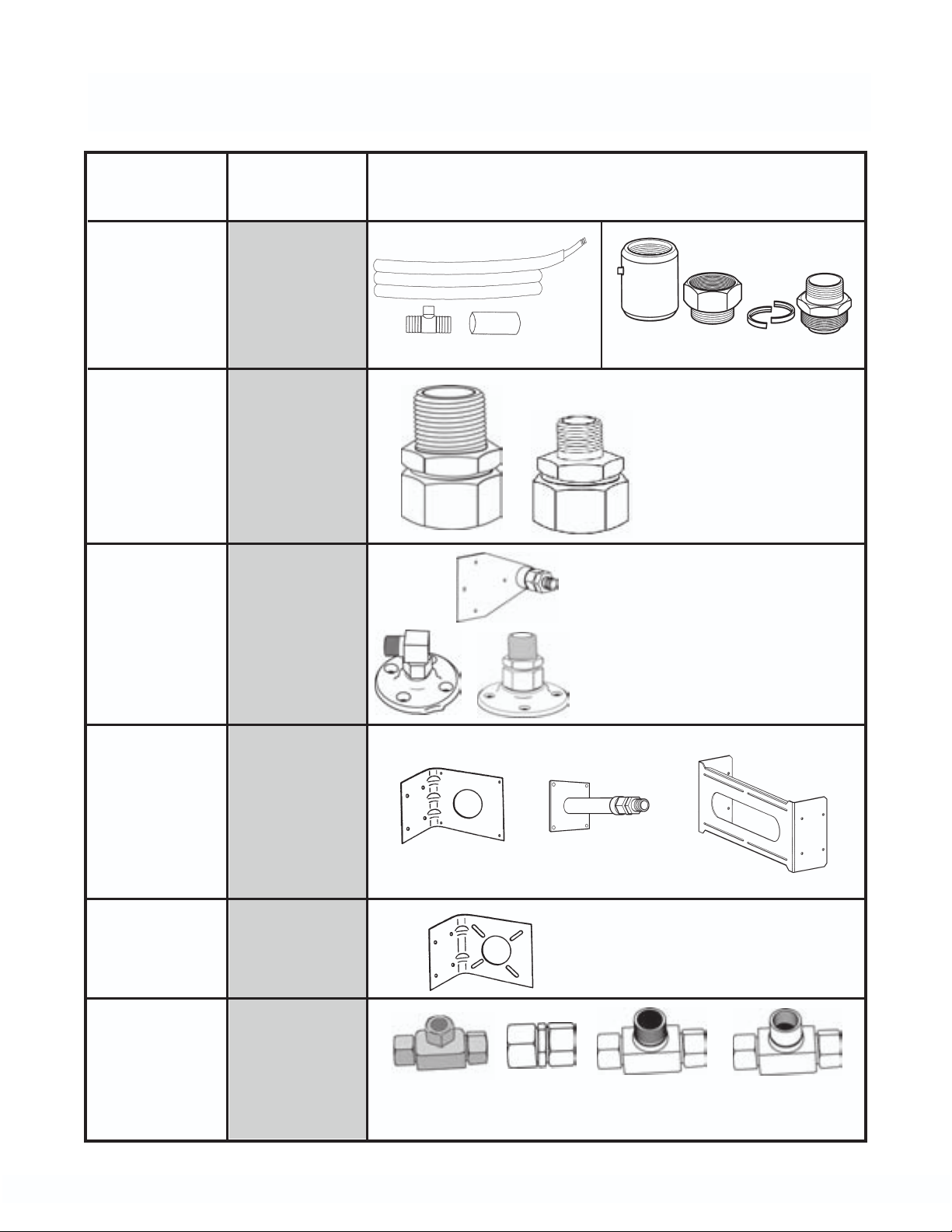
AutoFlare®Fittings
Component Material Description/Dimensions
PS PS-II
TracPipe PS
&
PS-II
Accessories
Black
Polyethylene
Sleeved
TracPipe
Vent Tee
Heat Shrink Cuff
Vent Nut Split Adaptor
Coupling Rings
Straight
Mechanical
Fitting
Reducer
Fitting
Termination
and Flange
Mount
Fittings
Straight
and 90 Elbow
Meter
Termination
Fitting
Stud
Bracket
Brass
Fitting
Autoflare
Insert
Brass
Fitting
Autoflare
Insert
Malleable
Iron or Brass
Flange
Brass Fitting
Autoflare
Insert
Galv. steel
Mounting
Bracket
Sizes: 3/8, 1/2, 3/4, 1, 1-1/4, 1-1/2
and 2 inch
Note size 3/8 fitting has
either 1/2" NPT or 3/8"
NPT Thread
Sizes: 3/8, 1/2, 3/4, 1 inch
and 1-1/4 inches
Note size 3/8 fitting has either
1/2" NPTor 3/8" NPT Thread
Elbow Sizes: 3/8 in. and 1/2 in.
Flange
Mounting
Bracket
Tee
Fitting
&
Coupling
Galv. Steel
Brass Tee
Fitting
& Coupling
Autoflare
Insert
One size fits all:
Size
3/8 through 1-1/4 inches
Sizes: 3/8, 1/2, 3/4 and 1 inch
Reducer tees available for 1/2, 3/4 and 1 inch sizes
10
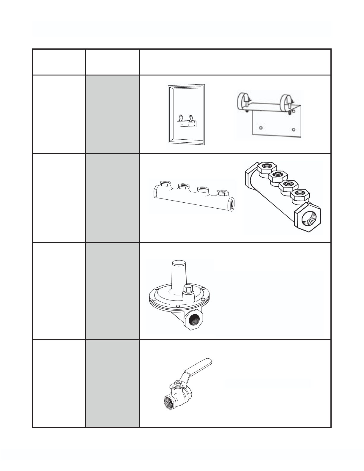
TracPipe Accessories
Component Material Description/Dimensions
Load
Center
Manifold
Bracket
Multi-
Port
Manifolds
Painted Steel
Galvanized
Steel
Malleable
Iron
Poly Coated
Pressure
Regulators
Shut
Off
Valves
Cast
Housing
Suitable
for
Outdoor
Use
Brass
Housing
with
Stainless
Steel
Ball
Sizes: 1/2 inch & 3/4 inch & 1-1/4 inch
Regulator includes approved vent lim-
iting device for REG 3 (1/2 in.) and
REG 5A (3/4 in.).
Note: Stainless steel High Pressure tags
are available for use where required by
code
Sizes: 1/2 inch & 3/4 inch
11
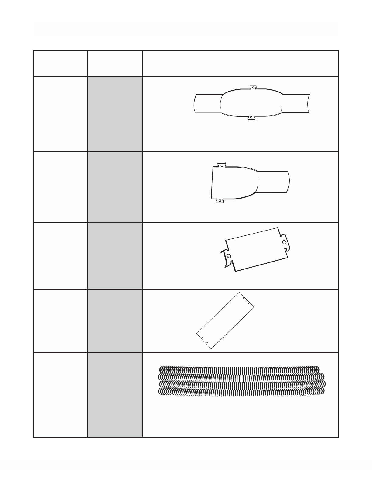
TracPipe Accessories
Component Material Description/Dimensions
Full
Striker
Plate
Half
Striker
Plate
Quarter
Striker
Plate
Carbon
Steel
Hardened
size: 3" x 12"
Carbon
Steel
Hardened
size: 3" x 7"
Carbon
Steel
Hardened
size: 3" x 2"
6 x 17
Striker
Plate
Floppy
Strip
Wound
Conduit
Carbon
Steel
Hardened
size: 6" x 17"
Type RW
Galvanized
Steel
sizes: Fits 3/8", 1/2", 3/4", 1", 1-1/4", 1-1/2"
and 2" TracPipe
12
r
CHAPTER 3
SYSTEM CONFIGURATIONS AND SIZING
SECTION 3.1 — SYSTEM
CONFIGURATIONS
There are several piping system options
available to the installer using TracPipe gas
piping material. This flexibility of design is
one of the major benefits of CSST.
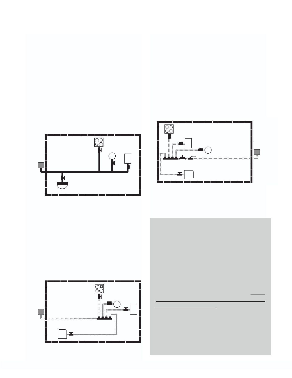
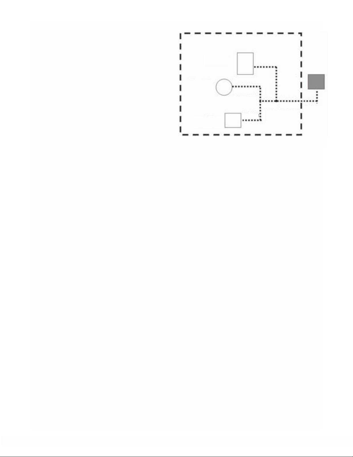
3.1A — LOW PRESSURE SYSTEMS
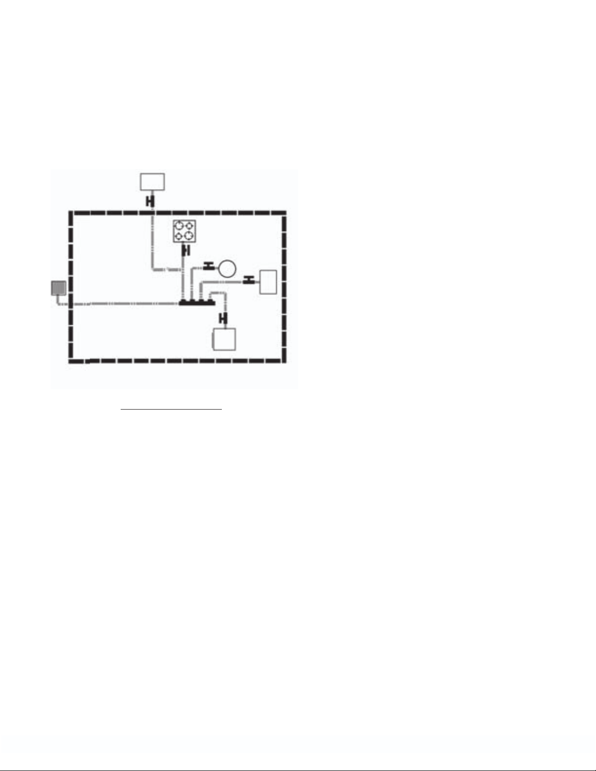
1. SERIES: A series layout is the most common arrangement utilized for black iron
pipe. This consists of a main run with tees
branching off to each appliance.
range
50 CFH
gas meter
163 CFH
water heater
30 CFH
furnace
60 CFH
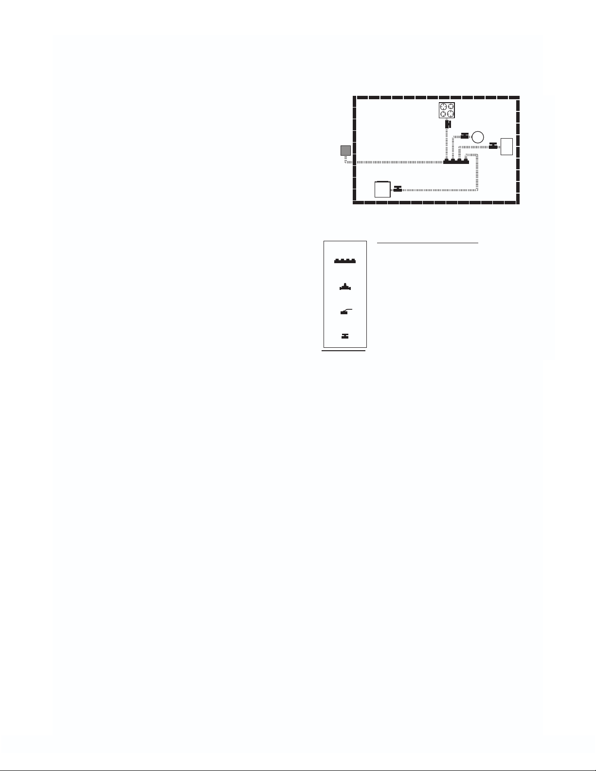
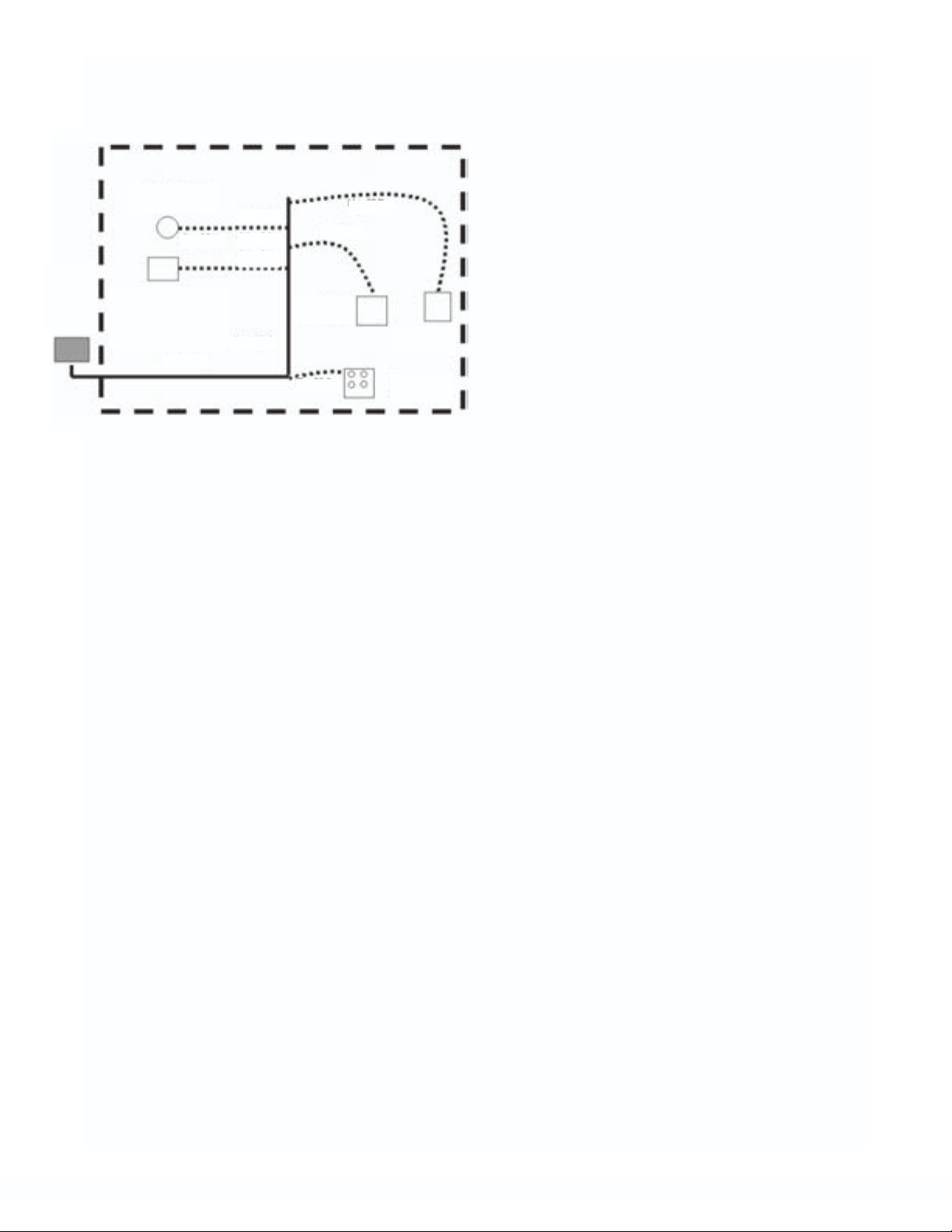
3.1B — DUAL PRESSURE SYSTEMS
Elevated pressure systems (2 psi for residential and up to 5 psi for commercial installations) are usually piped with one or more
house line regulators (pounds-to-inches) followed by a manifold and runs to each of the
appliances. It is possible that these runs to
appliances may contain tees branching off to
an additional appliance where gas loads permit.
range
55 CFH
furnace
80 CFH
E
C
dryer
D
30 CFH
B
water heater
40 CFH
gas mete
A
205 CFH
2 PSI
fireplace
18 CFH
Series Layout
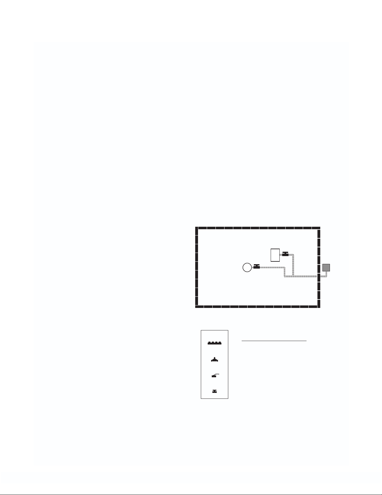
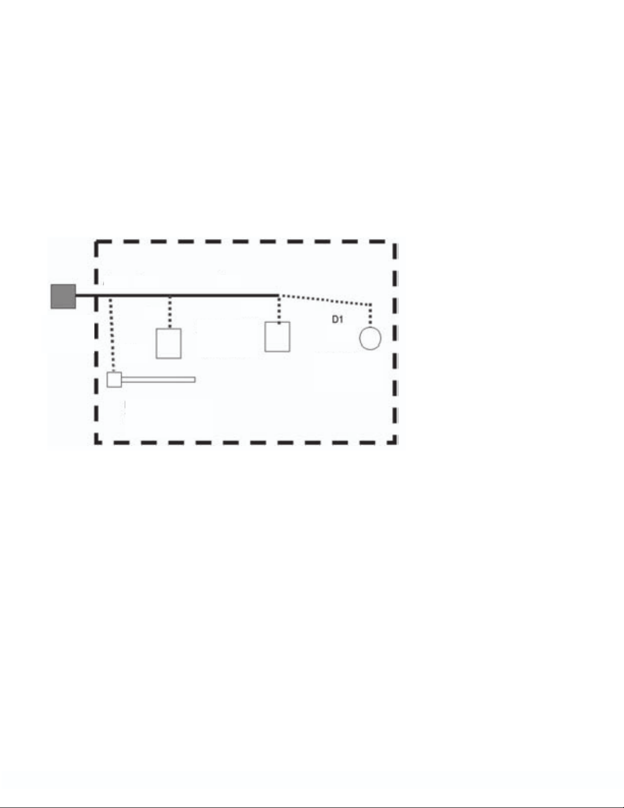
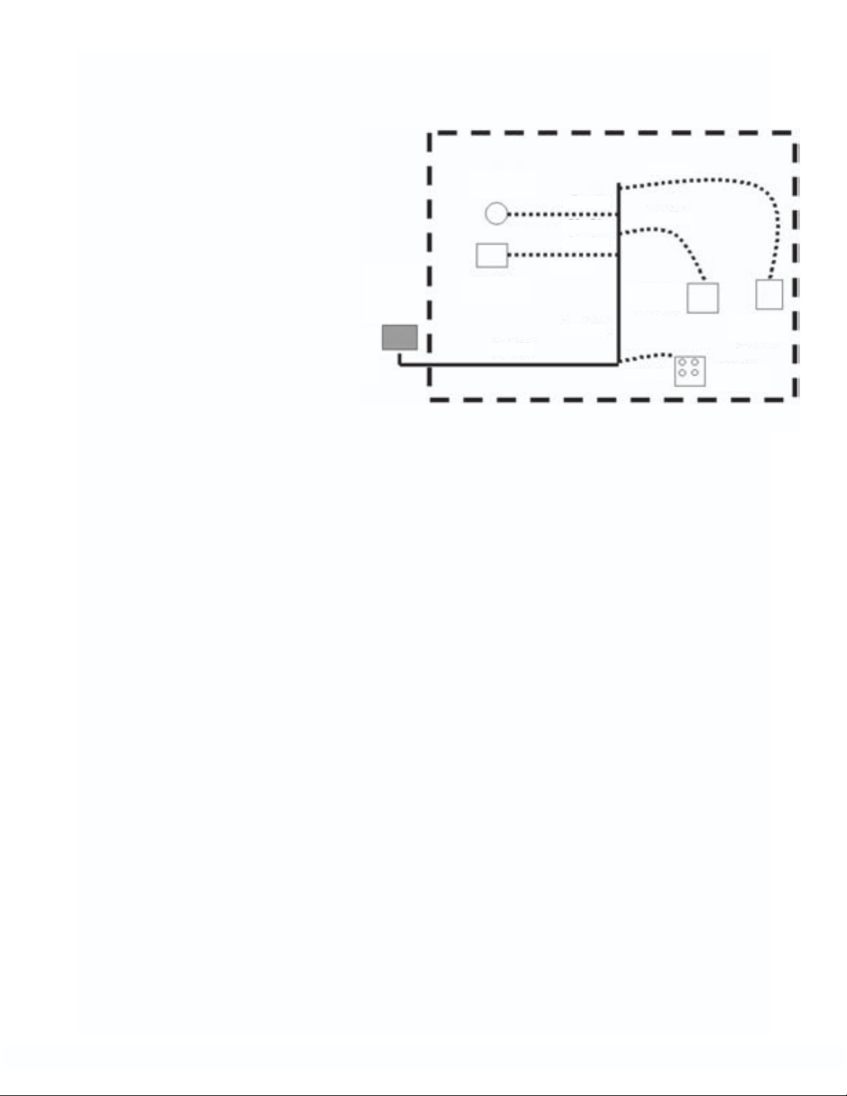
2. PARALLEL: A parallel system consists of a
central distribution manifold with branch
runs to the appliances. This is usually
accomplished by providing a main supply
line to a manifold and installing “home
runs” to each appliance location. In the
parallel system shown below the pressure
is not elevated above 1/2 pound and no
regulator is required.
range
55 CFH
water heater
1/2 PSI
gas meter
205 CFH
A
dryer
30 CFH
Parallel Layout
40 CFH
C
B
D
furnace
80 CF
H
E
Dual Pressure System Layout
NOTE:
HYBRID SYSTEMS – FLEXIBLE GAS
PIPE and RIGID BLACK PIPE COMBINATIONS.
In low or medium pressure systems,
it is often advantageous to use both corrugated stainless steel tubing and rigid pipe in
the same system. This is the case when a
larger diameter main branch is required to
provide for the total appliance load in a paral-
lel system. TracPipe is certified for use in
combination with black iron pipe and copper
tube gas piping systems. For additional information on Hybrid Systems see examples
showing the method for sizing hybrid systems
using both TracPipe and black iron pipe
These are included in the SIZING EXAMPLES
section of this manual. Refer to Section 3.2C
13

SECTION 3.1C — SYSTEM DESIGN
1. Prepare a sketch or layout of the gas piping system you are about to install. The
information you will need is the location of
each appliance, the point of delivery
(location of utility meter or second stage
LP regulator), appliance load demands,
and possible pipe routing locations. The
load demand data is usually available on
the appliance manufacturer’s nameplate,
or can be provided by the builder.
2. Determine local piping restrictions prior to
installing flexible gas piping. The major
code bodies in North America have written
Corrugated Stainless Steel Tubing into the
latest revisions of their mechanical codes,
but local and state adoption of these
codes often lags behind. CONFIRM THA
THE LOCAL CODE AUTHORITY HAS
ACCEPTED THE USE OF FLEXIBLE GAS
PIPING. Your TracPipe distributor should
be able to provide that information but
confirmation by the installer should be
made where there is a question.
SECTION 3.1D — SYSTEM
PRESSURE CHOICES
1. NATURAL GAS-Determine the delivery
pressure provided by the Local
Distribution Utility where the piping will be
installed.
ances manufactured for use in the US
and Canada are designed to operate
up to a maximum of 14 inches water
column.
c. ELEVATED PRESSURE-2 PSI -Is the
highest natural gas pressure usually
supplied within residential buildings in
North America. This pressure always
requires the installation of a poundsto-inches house line regulator between
the utility meter set and the appliances.
2. PROPANE (LP GAS)-Is typically supplied
within residential buildings at 11 inches
water column, set at the second stage reg-
T
ulator mounted outside the building.
Propane can also be utilized at mediumpressure, with the use of a 13-14 inch setting. For 2 PSI Propane elevated pressure
the Maxitrol regulator used is FGP-REG3P.(which is factory set at 11 inches water
column.) A second stage regulator which
reduces 10 psi from the tank to 2 psi must
be used. (e.g. Fisher model R312E).
NOTE: TracPipe has been tested by CSA
International (formerly AGA Laboratories) for a
working pressure of 125 PSI for sizes 3/8" through
1-1/4" and 25 PSI for sizes 1-1/2 & 2".
a. LOW PRESSURE-6 to 7 inches water
column-equivalent to 4 ounces or 1/4
pound is the standard pressure supplied by natural gas utilities in the USA
and Canada.
b. MEDIUM PRESSURE-1/2 POUND-12
to 14 inches water column-Is available
from many natural gas utilities as an
enhanced pressure supply. The increase
in pressure provides for reductions in
pipe size and does not require a pressure regulator. Most natural gas appli-
PRESSURE CONVERSION CHART
1/4 PSI = 7" w.c. = 4 oz.
1/2 PSI = 14" w.c. = 8 oz.
1 PSI = 28" w.c. = 16 oz.
2 PSI = 56" w.c. = 32 oz.
14
SECTION 3.2 SIZING METHODS and EXAMPLES
low pressure
gas meter
100 CFH
water heater
35 CFH
furnace
65 CFH
B
A
C
SECTION 3.2A — USE OF SIZING
TABLES
This Chapter includes flexible gas piping sizing procedures for both low pressur e and elevated pressure systems. Every piping system
introduces pressure loss to the fluid flowing
within. The amount of loss depends on the
piping size and the gas flow, expressed in
cubic feet per hour (and converted to BTU’s).
The object of the sizing exercise is to determine the smallest size piping which will introduce the allowed pressure loss or drop within the length of piping required. Sizing Tables
(Capacity Charts) provide the maximum flow
capacity for a given length of run for each
pipe size. A different sizing table is used for
each system pressure and pressure drop
combination.
1. The low pressure series system (standard
arrangement) is sized in the same way as a
conventional low pressure black iron pipe
system using TracPipe sizing tables or
tables found in National Fuel Gas Code
NFPA 54. This method is known as the
“Branch Length Method”. Pressure drop in
a low pressure system is usually limited to
1/2 inch water column over the system.
This part of the system is sized the same
as a low pressure system, except that a
special table N-3 is used allowing 3 inches
of water column drop. These lines are typically sized for only one appliance load
installed as a “home run” from the manifold.
SECTION 3.2B — SIZING EXAMPLES
BRANCH LENGTH METHOD
To size each of the following systems, determine the required size for each section and
outlet. To size each section of the system,
determine both the total gas load for all appliances and the maximum distance (longest
length) in which a particular section delivers
gas.
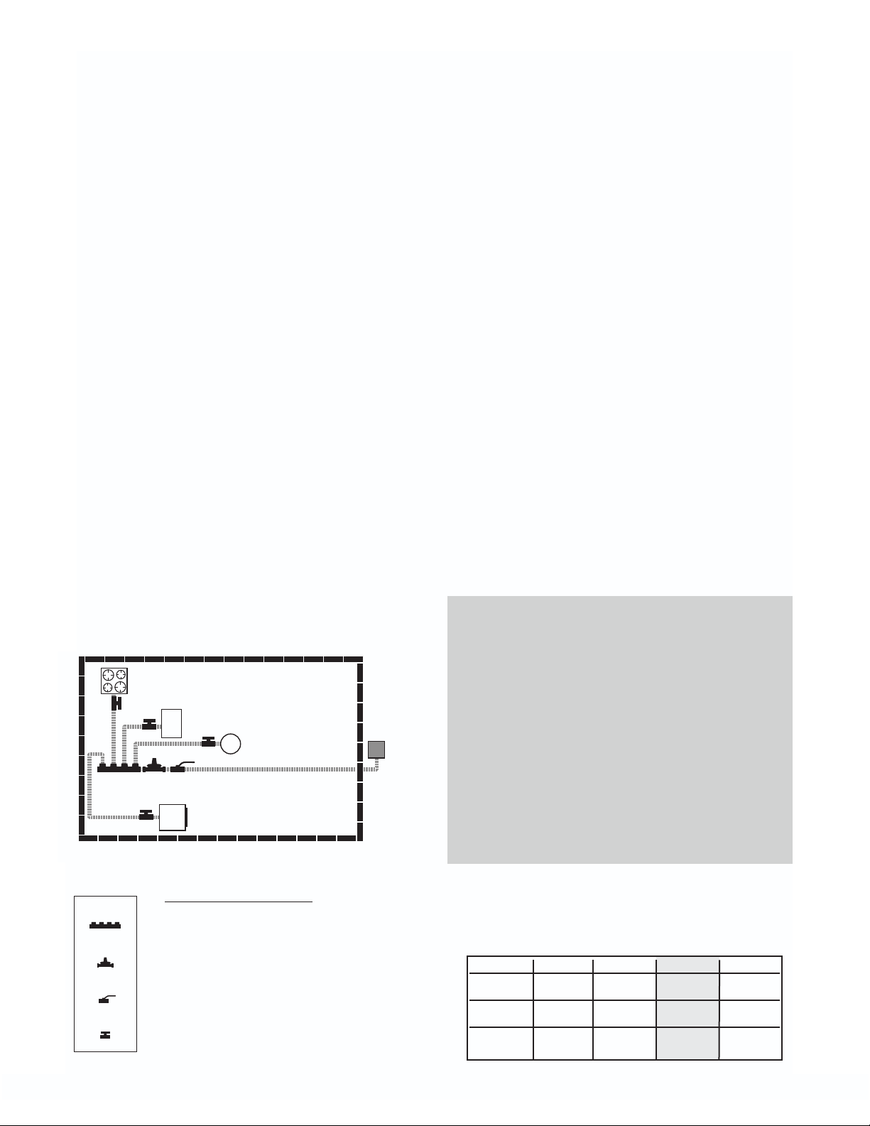
EXAMPLE 1 LOW PRESSURE SYSTEM
SERIES ARRANGEMENT
2. Elevated pressure systems incorporate two
operating pressures downstream of the utility meter set. The first pressure, set by the
service regulator at the meter, is usually 2
PSI. This part of the system is sized separately and ends at the pounds-to-inches regulator. The allowable pressure loss for this
part of the system must be added to the
effect of the regulator to determine the available pressure at the regulator outlet. The
chart in Section 4.8B shows pressure losses
for maximum loads through the regulator.
3. For a 2 PSI system, the proper drop is usu-
ally 1 PSI for this part of the system; this
allows for the approximate 3/4 PSI regulator drop downstream and provides the 1/4
PSI (6-7 inches w.c.) necessary for appliances. The regulator reduces the pressure
from pounds to 8 inches water column.
Figure 3-1
manifold
LENGTH OF RUNS
A = 10 Feet
pressure regulator
B = 10 Feet
C = 15 Feet
line shut-off
appliance shut-off
Supply pressure 6 inches w.c.
Allowable drop 0.5 inches w.c.
1. The system presented in figure 3-1 is typical of a single family installation in which
there are a limited number of appliances
located in one general area. The supply
pressure is 6 inches water column and the
allowable drop is 1/2 inch.
15
2. To size section A, determine the longest
run from the meter that includes section A
and the total gas load it must deliver:
• Meter to Furnace is 20 ft. (A+B)
parallel. The MEDIUM PRESSURE SYSTEM
(1/2 PSI ) allows a higher pressure drop
(6 inches Water column) than is available
with low pressure systems.
• Meter to Water Heater is 25 ft. (A+C).
This is the longest run.
• Determine the maximum load transported by Section A
• Furnace plus Water Heater = 100 cfh
(100,000 BTU)
• Select Table N-1 “Low Pressure 6
inches- 1/2 inch w.c. drop"
• Using the longest run method, select
the column showing the measured
length, or the next longest length if the
table does not give the exact length.
Referring to table N-1 the column for 25
feet of piping shows that sizes 3/8 and
1/2 are too small and the next available
size is 3/4 supplying 132 cfh.
• The correct size is 3/4".
3. To size Section B, determine the length of
run from the meter to the Furnace and the
load delivered:
• Length is 20 ft (A+B) and load is 65 cfh
(65,000 BTU)
• Table N-1 shows that size 1/2" supplies
67 cfh
• The correct size is 1/2".
4. To size Section C, determine the length of
run from the meter to the Water Heater and
the load delivered:
• Length is 25 ft (A+C) and load is 35 cfh
(35,000 BTU)
• Table N-1 shows that size 1/2" is
required, because size 3/8" only supplies 27 cfh (27,000 BTU)
• The correct size is 1/2"
EXAMPLE 2 MEDIUM
PRESSURE 12-14 INCHES W.C. (1/2 PSI)
1. The system shown in Figure 3-2 is typical
of a single family installation with several
appliances. The arrangement chosen is
range
55 CFH
water heater
1/2 PSI
gas meter
205 CFH
dryer
30 CFH
40 CFH
C
B
A
D
furnace
80 CF
H
E
Figure 3-2
LENGTH OF RUNS
manifold
A = 10 Feet
B = 20 Feet
pressure regulator
C = 10 Feet
D = 40 Feet
line shut-off
appliance shut-off
E = 10 Feet
Supply pressure 1/2 PSI (12"-14"
w.c.)
Allowable drop: 6" w.c.
2. To size SECTION A, determine the
LONGEST RUN from the meter to the furthest appliance.
• Meter to dryer is 50 feet (10+40) A+D
• Determine maximum load transported by section A
• Dryer + Range + Water heater +
Furnace = 205 cfh ( 205,000 BTU)
• Select table N-4 “Medium Pressure
1/2 PSI with 6 inch drop“.
Table N-4 shows that 1/2" size is too
small for 205 cfh at 50 ft. but 3/4"
can handle 315 cfh.
• The correct size is 3/4"
3. To size SECTION B, the distance from the
meter to the range is 30 ft (10+20) A+B
• Load is 55 cfh ( 55,000 BTU )
• Table N-4 shows that 3/8" size can
handle 90cfh
• The correct size for section B is 3/8"
4. To size SECTION C, the distance from the
meter to the water heater is 20 ft (10+10) A+C
• Load is 40 cfh ( 40,000 BTU )
• Table N-4 shows that that 3/8" size
16
can handle 112cfh
r
• The correct size for section C is 3/8"
5. To size SECTION D, the distance from the
meter to the dryer is 50 ft (10+40) A+D
• Load is 30 cfh ( 30,000 BTU )
• Table N-4 shows that that 3/8" size
can handle 69cfh at 50 feet
• The correct size for section D is 3/8"
6. To size SECTION E, the distance from the
meter to the furnace is 20 ft (10+10) A+E
• Load is 80 cfh ( 80,000 BTU )
• Table N-4 shows that that 3/8" size
can handle 112cfh at 20 feet
• The correct size for section E is 3/8"
EXAMPLE 3 ELEVATED
PRESSURE 2 PSI SYSTEM
PARALLEL ARRANGEMENT
1. The system shown in figure 3-3 is adapted
for multifamily or single family application
with an extended (100 feet) tubing run from
the meter to the regulator The 2 PSI system
is well adapted to handle the long runs
required in multifamily buildings with centralized meter banks.
• furnace + water heater + dryer + range =
80 cfh + 40 cfh + 30 cfh + 55cfh = 205
cfh (205,000 BTUH) Select Table N-5
“Elevated Pressure 2 PSI with 1 PSI
drop’’ This is the standard table chosen
to stay within the Maxitrol 325-3 regulator capacity. See note below.
• Length is 100 ft.
• Table N-5 shows that 3/8" size is too
small for 205 cfh but 1/2" can handle
222cfh.
• The correct size is 1/2"
3. To size each of the other sections:
Select Table N-3 “ Regulator Outlet 8.0
inches w.c with a dr op of 3.0 inches w.c
• Section B is 15 feet with a 40 cfh load
3/8" has a capacity of 90 cfh
• Section C is 10 feet with a 80 cfh load
3/8" has a capacity of 112 cfh
• Section D is 25 feet with a 30 cfh load
3/8" has a capacity of 69 cfh
• Section E is 20 feet with a 55 cfh load
3/8" has a capacity of 78 cfh
• The correct size for all these runs is 3/8"
2. To size section A determine the entire gas
load it will deliver
range
55 CFH
furnace
80 CFH
E
C
dryer
D
30 CFH
B
water heater
40 CFH
2 PSI
gas mete
A
205 CFH
Figure 3-3
LENGTH OF RUNS
manifold
A = 100 Feet
B = 15 Feet
pressure regulator
line shut-off
appliance shut-off
C = 10 Feet
D = 25 Feet
E = 20 Feet
Supply pressure 2 PSI
Allowable drop: 1 PSI up to reg.
3 inches w.c.-reg. to appliance
NOTE: at 250 cfh gas flow the
FGP-REG-3 regulator contributes
3/4 PSI drop to the system. (see
chart below). The low pressure
part of the system downstream of
the regulator requires the standard
1/4 PSI to power appliances.
Deducting the 3/4 psi drop and the
1/4 psi load the maximum allowable drop for the meter run is 1
psi. Start with 2 PSI - 3/4 drop for
regulator - 1/4 left for Appliance =
1 PSI drop for section A.
Capacities and Pressure Drop
Pressure Drop through Regulator
Based on flow in cubic feet per hour
P/N 7" w.c. 1/2 psi 3/4 psi 1 psi
FGP-REG-3
FGP-REG-5A
FGP-REG-7L
145 204 250 289
338 476 583 673
690 972 1191 1375
17
EXAMPLE 4 MEDIUM
PRESSURE 12-14 INCHES W.C. 1/2 PSI)
PARALLEL SYSTEM WITH A SERIES BRANCH
1. The system shown in Figure 3-4 has a barbeque installed nearby the range. A parallel arrangement was chosen for the medium pressure system (12 inch W.C. with 6
inches W.C. drop) with a single run feeding
both range and barbeque in series.
D
1/2 PSI
gas meter
260 CFH
C
A
E
F
B
G
3. To size SECTION B, the line from the manifold serves both the range and the barbeque.
• Total load is 105 CFH (105,000 BTUH)
• Longest length is 75 feet (A+B+C) from
the meter to the barbeque
• Table N-4 shows that size 1/2" can
handle 116 CFH at 80 ft
• The correct size is 1/2"
4. To size SECTION C, the distance from the
meter to the barbeque is 75 ft (A+B+C)
• Load is 55 CFH (55,000 BTUH).
• Table N-4 shows that size 3/8" can only
handle 54 CFH at 80 ft
• The correct size is 1/2"
5. To size SECTION D, the distance from the
meter to the range is 65 ft (A+B+D)
• Load is 50 CFH (50,000 BTUH).
• Table N-4 shows that size 3/8" can
handle 58 CFH at 70 ft
• The correct size is 3/8"
Figure 3-4
LENGTH OF RUNS
A = 20 Feet
B = 35 Feet
C = 20 Feet
D = 10 Feet
E = 10 Feet
F = 10 Feet
G = 15 Feet
2. To size SECTION A, determine the length
of the longest run from the meter and the
entire gas load it must deliver:
• Range + Barbeque + Water heater +
Furnace +Dryer = 260 CFH (260,000
BTUH).
• Meter to barbeque is 75 ft (A+B+C) This
is the longest length
• Select Table N-4 Medium Pressure.
Table N-4 shows that 1" is required for
260 CFH at 75 ft (using next longer distance 80 ft column)
• The correct size is 1"
6. To size SECTION E, the distance from the
meter to the water heater is 30 ft (A+F)
• Load is 40 CFH (40,000 BTUH).
• Table N-4 shows that size 3/8" can
handle 81 CFH at 70 ft
• The correct size is 3/8"
7. To size SECTION F, the distance from the
meter to the furnace is 30 ft (A+E)
• Load is 80 CFH (80,000 BTUH).
• Table N-4 shows that size 3/8" can
handle 81 CFH at 30 ft
• The correct size is 3/8"
8. To size SECTION G, the distance from the
meter to the dryer is 35 ft (A+G)
• Load is 35 CFH (35,000 BTUH).
• Table N-4 shows that size 3/8" can
handle 78 CFH at 40 ft
• The correct size is 3/8"
18
SECTION 3.2C — SIZING HYBRID
SYSTEMS
(Black Iron and TracPipe Combination)
To size a commercial or a residential system
with a rigid black iron trunk line and flexible
TracPipe branches feeding the appliances,
you will need both the standard gas piping
capacity tables for black iron printed in many
plumbing and mechanical codes (and contained in both National and International Fuel
Gas Code) and the TracPipe Capacity Tables
printed later in this manual.
B
A
Low-pressure
gas meter
715 CFH
B1
A1
Radiant Heater
175 CFH
LENGTH OF RUNS
A = 15 Feet C = 20 Feet
A1 = 45 Feet C1 = 5 Feet
B = 15 Feet D1 = 20 Feet
B1 = 10 Feet
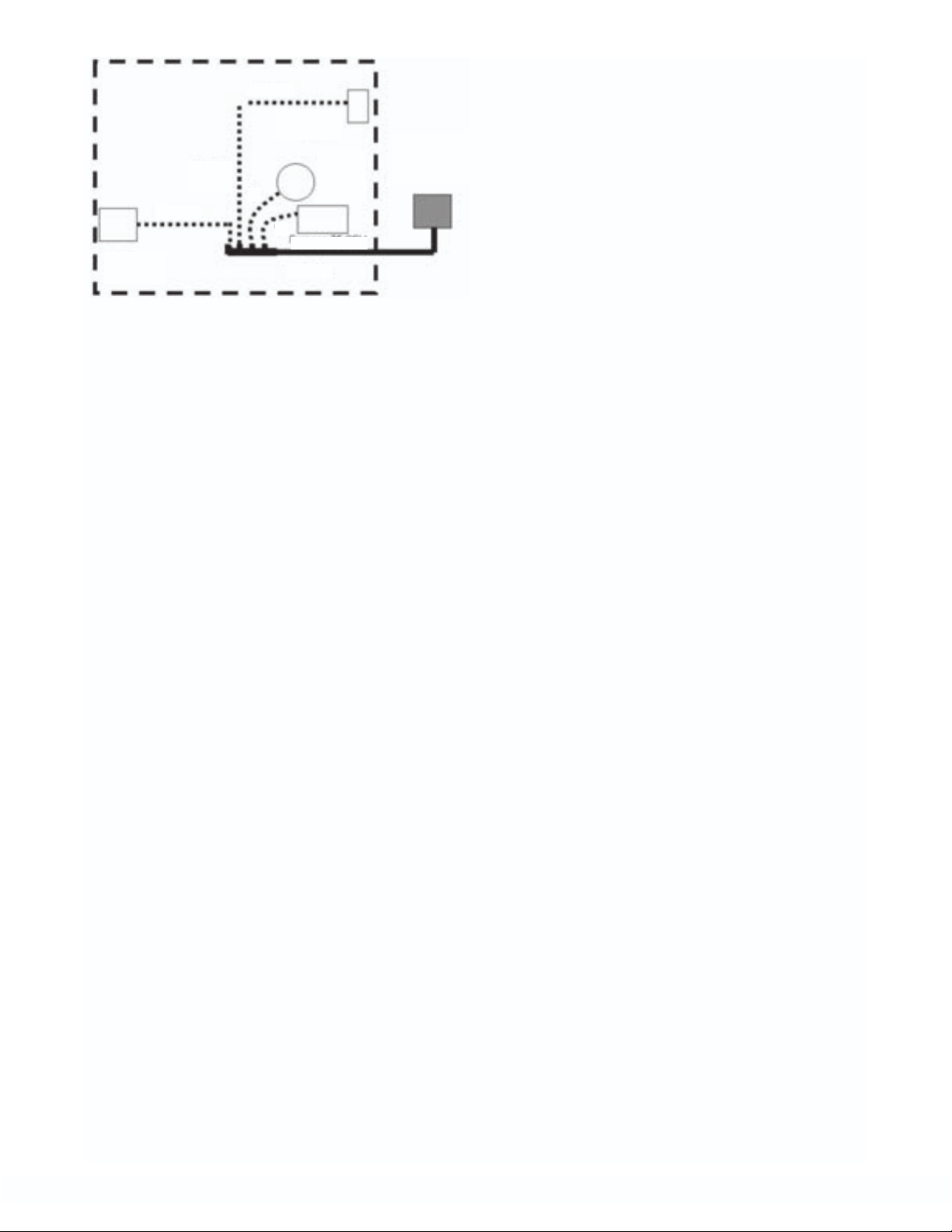
EXAMPLE 5 LOW PRESSURE HYBRID SYSTEM (Black Iron and TracPipe Combination)
SERIES ARRANGEMENT
1. The system shown in figure 3-5 is a typical
commercial building with 4 appliances. The
gas pressure for this example is standard low
pressure with 6-inch supply pressur e and 0.5inch pressure drop.
2. To determine rigid pipe size (section A)
determine the longest run from the meter
to the furthest appliance:
Meter to Water Heater Add A + B + C + D1
= 70 ft.
Total Load is 715 CFH (715,000 BTU)
C
C1
Unit heaters
2 x each
250 CFH
Figure 3-5
Section A correct size is 1 1/2 inch black
pipe
3. To determine rigid pipe size (section B)
reduce load by the load carried in section A1
to Radiant Heater (175 CFH). Use same
number for length: 70 ft. is longest run.
Load for this section is 540 CFH
Section B correct size is 1 1/2 inch black pipe
4. To determine rigid pipe size (section C)
reduce load further by the load carried in
section B1 to first unit
heater (250 CFH). Use
same number for length:
70 ft. is longest run.
Load for this section is
290 CFH
Section C correct size is 1
1/4 inch black pipe
D1
Water heater
40 CFH
5. To determine TracPipe
sizing for the branch runs
the length to be used is
the total length of black
pipe plus TracPipe from
the meter to that appliance. The load used is the
load of the individual
piece of equipment.
6. To determine the size of TracPipe (section
D1) the length is 70 ft and the load is 40
CFH. Using Table N-1:
Section D correct size is 3/4 inch
7. To determine the size of TracPipe (section
C1) the length is 55 ft and the load is 250
CFH. Using Table N-1:
Section C1 correct size is 1 1/2 inch
8. To determine the size of TracPipe (section
B1) the length is 40 ft and the load is 250
CFH. Using Table N-1:
Section B1 correct size is 1 1/4 inch
9. To determine the size of TracPipe (section
A1) the length is 60 ft and the load is 175
CFH. Using Table N-1:
Section A1 correct size is 1 1/4 inch
19
EXAMPLE 6 LOW PRESSURE HYBRID SYSTEM (Black Iron and TracPipe Combination)
SERIES ARRANGEMENT
Water heater
Low
pressure
meter
230 CFH
40 CFH
Furnace
70 CFH
A=40 ft
G=25 ft
D=10 ft
C2=6 ft
C1=6 ft
F=30 ft
35 CFH
B=20 ft
E=20 ft
H=40 ft
I=30 ft
Dryer
Figure 3-6
Fireplace
30 CFH
Range
55 CFH
5. Section C1, the longest run is 120 ft and
load is reduced to 105. Correct size is 1".
6. Section C2, the longest run is 120 ft and
load is reduced to 70. Correct size is 3/4".
7. Section D, the longest run is 120 ft and
load is reduced to 30. Correct size is 1/2".
8. Section E, length is 60 ft and the load is
55 CFH. From Table N-1 the correct size
is 3/4".
9. Section F, length is 90 ft and the load is 70
CFH. From Table N-1 the correct size is
3/4".
1. The system presented in figure 3-6 is a
typical residence with 5 appliances. The
supply pressure is 7 inches w.c. The
allowable drop is 1-inch w.c. total. (black
iron drop is 0.5 in. w.c. and TracPipe
drop is 0.5 in. w.c.) Note: Check with your
local inspection department and/or gas
utility before sizing any low-pressure system with a total drop of more than 0.5 in.
w.c.
2. The black iron trunk line (A+B+C1+C2+D)
will first be sized for a drop of 0.5 in., w.c.
in accordance with the standard method
(longest total run) and each TracPipe
branch run to an appliance will then be
sized for 1.0 in w.c. drop based on the
length from that appliance back to the
meter. The maximum pressure drop to
each appliance will be 1.0-inch w.c.
3. The longest total run is 120 ft. (total length
of all black iron sections and TracPipe
section to the furthest appliance). The
total load is 70+40+55+35+30=230 CFH.
Correct size for A is 1-1/4"
10. Section G, length is 95 ft and the load is
40 CFH. From Table N-1 the correct size
is 3/4".
11.Section H, length is 120 ft and the load is
30 CFH. From Table N-1 the correct size
is 3/4".
12.Section I, length is 95 ft and the load is 35
CFH. From Table N-1 the correct size is
3/4".
EXAMPLE 7 LOW PRESSURE HYBRID STEEL
PIPE AND TRACPIPE-PARALLEL ARRANGEMENT-MANIFOLD-USING THE LONGEST RUN
METHOD
1. The system presented in figure 3-7 is typical of a residential installation with four
appliances. The supply pressure is 7-8
inches water column. The system will be
sized with 0.5 inches w. c. drop for the
steel pipe trunk line and 1 inch w.c. drop
for the TracPipe branches. (Note: con-
firm that pressure drops larger than 0.5
inches water column are permitted in your
jurisdiction)
4. Section B, the longest run remains 120 ft
but the load is reduced to 175 CFH.
Correct size is 1".
20
D=30 ft
Fireplace
Range
55 CFH
E=25 ft
B=10 ft
C=10 ft
Figure 3-7
B
30 CFH
Water
heater
35 CFH
C
Furnace 75 CFH
A=20 ft
Low pressure
gas meter
195 CFH
2. To size the steel pipe trunk line, determine
the longest run from the meter to any
appliance and the total load. The longest
run is to the fireplace.
• Meter to fireplace is 50 ft (A + D)
• Total load is 195 CFH (75 + 35 + 30 + 55)
Using steel pipe Table SP-1 (page 77) following the 50 ft column down, the correct
size for the steel pipe is 1".
3. To determine the size of the TracPipe run
“C” to the furnace use the load through
that branch (75 CFH) and calculate the
length from the meter to the furnace.
• Meter to furnace is 30 ft (A + B)
• Furnace load is 75 CFH
Using Table N-2A the 1.0-inch w.c. pressure drop chart for TracPipe. Follow the
30 ft column down, the correct size for the
furnace branch line “C” is 1/2".
4. To determine the size of the TracPipe run
“B” to the water heater use the load
through that branch (35 CFH) and calculate the length from the meter to the water
heater.
• Meter to water heater is 30 ft (A + C)
• Water heater load is 35 CFH
Using Table N-2A the 1.0-inch w.c. pressure drop chart for TracPipe. Follow the
30 ft column down, the correct size for the
water heater branch line “B” is 1/2".
5. To determine the size of the TracPipe run
“D” to the fireplace use the load through
that branch (30 CFH) and calculate the
length from the meter to the fireplace.
• Meter to fireplace is 50 ft (A + D)
• Fireplace load is 30 CFH
Using Table N-2A the 1.0-inch w.c. pressure drop chart for TracPipe. Follow the
50 ft column down, the correct size for the
fireplace branch line “D” is 1/2".
6. To determine the size of the TracPipe run
“E” to the range use the load through that
branch (30 CFH) and calculate the length
from the meter to the range.
• Meter to range is 45 ft (A + E)
• Range load is 55 CFH
Using Table N-2A the 1.0-inch w.c. pressure drop chart for TracPipe. Follow the
50 ft column down, the correct size for the
range branch line “D” is 1/2".
SECTION 3.2D — ALTERNATE
SIZING METHOD:
SUM OF PRESSURE LOSS
CALCULATIONS
1. In addition to the longest run sizing
method, there is another approach to pipe
sizing, which yields results closer to the
actual friction loss results (obtained from
testing) for each section of an installed
gas piping system. This engineered
approach “Sum of Pressure Loss
Calculations” avoids the simplified, conservative approximations of the longest
run method. Mechanical engineers who
design piping systems understand that
placing a building’s entire load (theoretically) at the farthest equipment outlet is
not only inaccurate but will often yield
pipe sizes which are larger than necessary . The longest run method was devised
at a time when gas utilities could not
always guarantee a constant pressure at
every meter during times of high
demands; it is a conservative approach
and, although it is the customary sizing
approach in North America, other engineered calculations are permitted by most
codes.
21
2. Pressure Loss Calculations which sum up
friction losses in each section of a gas
piping system can provide a system
design with more accurate and possibly
smaller piping diameters than the traditional longest run method. These calculations utilize pressure loss charts for each
size of CSST, which have been developed
from actual test results. The maximum
flow capacity is predicted with more precision than with the longest run method.
The Sum of Pressure Loss method is
described below with tables providing
pressure loss per foot based upon the
total load supplied by that length of pipe
with all appliances operating.
3. The system designer has simply to determine the load and the length for each run. A
tentative size is chosen and pressure loss in
that leg is determined by multiplying the
loss per foot (inches w.c. from the chart) by
the length. Starting at the meter and working outward the pressure loss for each leg
is then summed up until the farthest appliance is reached. The total calculated loss is
then compared with the allowable loss,
which must not be exceeded from the
meter to the farthest appliance. The allowable pressure loss for each system is the
responsibility of the system designer, based
on model codes and on the available pressure at the meter set (or second stage regulator) and the pressure required for each
appliance (usually found on the manufacturer's data plate.) Current language in
many model codes states: The allowable
loss under maximum probable flow conditions, from the point of delivery to the inlet
connection of the appliance, shall be such
that the supply pressure at the appliance is
greater that the "minimum inlet pressure"
as stated on the appliance manufacturers
data plate. If the initial proposed design calculation yields a total pressure loss, which
is higher than allowed, simply go back and
calculate again with larger sizes, starting
from the meter.
USING SUM OF PRESSURE LOSS METHOD
Furnace
65 CFH
B=10 ft
Water Heater
35 CFH
Dryer
35 CFH
EXAMPLE 8 LOW PRESSURE SYSTEM
SERIES ARRANGEMENT
C2=10 ft
C1=5 ft A=10 ft
D=15ft
Figure 3-8
1. The system presented in figur e 3-8 is similar
to that in 3-1, a single-family installation with
the addition of one more appliance, a dryer.
The supply pressure is 6 inches water column and the allowable pressure drop is 1/2
inch.
2. To size section A, calculate the load carried by that section:
•Furnace plus Water Heater plus Dryer =
135 CFH (135,000 BTU)
Using Table PD-1 find pressure loss at 135
MBTU load through 3/4"TracPipe Average
of .019 and .022 is .021. Drop per foot is
0.021; multiply by length 10 feet = 0.21
drop
3. To size section B find the drop per foot for
the load carried by that section:
65 CFH (MBTU)
Using Table PD-1 find pressure loss at 65
MBTU through 1/2" TracPipe
Use the average of loss between 60 and
70 MBTU: Average of .019 and .027 is
.023 ; Drop per foot is 0.023 Multiply by
length 10 feet = 0.23 drop
Sum pressure loss meter to Furnace 0.21
+ 0.23 = .44 inches w.c
This leg is sized properly at 1/2" because
sum of loss is less than .5 in. w.c.
22
4. To size section C1 find the drop per foot
for the load carried by that section:
70 CFH (MBTU)
Using Table PD-1 find pressure
loss at 70 MBTU load through 1/2"
TracPipe
Drop per foot is .027; length is 5
ft; 5 X .027 is .135
5. To size section C2 find the drop
per foot for the load carried by
that section:
35 CFH (MBTU)
Low
Low
Pressure
Pressure
Meter
Meter
230 CFH
230 CFH
Using Table PD-1 find pressure
loss at 35 CFH load through 1/2"
TracPipe
Average of .008 and .004 is .006;
length is 10 ft; 10X .006 is .06
Sum pressure loss to water heater
0.21 + .135 + .06 = .405 inches
w.c
This leg is sized properly at 1/2" because
sum of loss is less than .5 in. w.c.
6. To size section D find the drop per foot for
the load carried by that section:
35 CFH (MBTU)
Using Table PD-1 find pressure loss at 35
MBTU through 1/2" TracPipe
Drop per foot is .006 (see number 4
above); Multiply by length 15 feet = .09
Sum pressure loss to dryer 0.21 + 0.135 +
.09 = .435 inches w.c.
This leg is sized properly at 1/2" because
sum of loss is less than .5 in. w.c.
The sum of pressure loss method allows the
addition of an appliance without increasing
trunk line size.
EXAMPLE 9 LOW PRESSURE HYBRID SYSTEM (Steel Pipe and TracPipe Combination)
SERIES ARRANGEMENT USING SUM OF
PRESSURE LOSS METHOD
1. The system presented in figure 3-9 is
identical to that in Figure 3-6: a singlefamily installation with 5 appliances. Low
pressure 6-7 inches and a pressure drop
of 0.5 inches water column. NOTE: in
Example 6 this system was sized using
the longest run method. Here we will use
the sum of pressure loss method discussed in section 3.2D.
Water Heater
40 CFH
G=25 ft
Furnace
70 CFH
A=40 ft
D=10 ft
C2=5 ft
C1=5 ft
F=30 ft
B=20 ft
Figure 3-9
H=40 ft
Dryer
35 CFH
E=30 ft
I=30 ft
Fireplace
30 CFH
Range
55 CFH
2. Begin by using pipe sizes determined in
Example 6 and determine if these are correct with this method. It is possible that
smaller pipe sizes may be sufficient; this
will be determined by calculating the sum
of pressure losses from the meter to each
appliance. To use this method a tentative
size will be assigned to each run and this
size will be confirmed or revised by the
calculation. The sum total loss of a run
from the meter to the appliance cannot
exceed the allowable pressure loss.
3. To determine pressure loss through section A (steel pipe trunk), use the load
through that section (230 CFH) and find
pressure loss per foot from the steel pipe
Schedule 40 Pressure Drop Curves Graph
Table SP-1. The 11/4 inch pipe diameter
line intersects the 230 CFH line at a pressure drop of .18 inches w.c. per 100 feet
of length. Multiply the length: 40 feet by
the loss per foot: 0.0018. The pressure
loss for this section is 0.072.
4. To determine pressure loss through section
B we use the load through that section
(175 CFH). Find pressure loss for 1" size
from the steel pipe graph in Table SP-1
- 0.6 per 100 feet. Multiply the length: 20
feet by the loss per foot: 0.006. The pressure loss for this section is 0.12.
23

5. To determine pressure loss through section C1 we use the load through that section (105 CFH). Find pressure loss for 1"
size from the steel pipe graph - 0.2 per
100 feet. Multiply the length: 5 feet by the
loss per foot: 0.002. The pressure loss for
this section is 0.01.
6. To determine pressure loss through section C2 we use the load through that section (70 CFH). Find pressure loss for 3/4"
size from the steel pipe graph - 0.38 per
100 feet. Multiply the length: 5 feet by the
loss per foot: 0.0038. The pressure loss for
this section is 0.019.
7. To determine pressure loss through section D we use the load through that section (30 CFH). Find pressure loss for 1/2"
size from the steel pipe graph - 0.31 per
100 feet. Multiply the length: 10 feet by the
loss per foot: 0.0031. The pressure loss for
this section is 0.031.
8. To determine pressure loss through section E (TracPipe drop to the range), use
the load through that section (55 CFH) and
find pressure loss from Table PD-1
Pressure Drop per Foot for TracPipe.
Trying the 3/4 inch column we find .004
inches per foot length (there is no 55 CFH
load listed, so we use 60 CFH). Multiply
the length: 30 feet by the loss per foot
.004. The pressure loss for this section is
0.12. Add the loss of section A to the loss
of section E for total loss from the meter to
range. 0.072 + 0.12 = 0.192. Since this is
less than the 0.5 allowable drop the correct size for section E is 3/4".
9. To determine pressure loss through section F (TracPipe drop to the furnace),
use the load (70 CFH) and find pressure
loss from Table PD-1. In the 3/4" column
we find 0.005. Multiply the length: 30 feet
by 0.005. The pressure loss for this section is 0.15.
Add the loss of sections A + B to the loss
of section F for total loss from meter to
furnace. 0.072 + 0.12 + 0.15 = 0.342. The
correct size for section F is 3/4".
10. To determine pressure loss through section G (TracPipe drop to the water
heater), use the load (40 CFH) and find
pressure loss from Table PD-1. In the 1/2"
column we find 0.008. Multiply the length:
25 feet by 0.008. The pressure loss for this
section is 0.20. Add the loss of sections A
+ B + C1 + C2 to the loss of section G for
total loss from meter to furnace. 0.072 +
0.12 + 0.01 + 0.019 + 0.20 = 0.421. The
correct size for section G is 1/2".
11. To determine pressure loss through section H (TracPipe drop to the fireplace),
use the load (30 CFH) and find pressure
loss from Table PD-1. In the 1/2" column
we find 0.004. Multiply the length: 40 feet
by 0.004. The pressure loss for this section is 0.16. Add the loss of sections A + B
+ C1 + C2 + D to the loss of section H for
total loss from meter to furnace. 0.072 +
0.12 + 0.01 + 0.019 + 0.031 + 0.16 =
0.412. The correct size for section H is
1/2".
1
2. To determine pressure loss through section I (TracPipe drop to the dryer), use the
load (35 CFH) and find pressure loss from
Table PD-1. In the
0.006. Multiply the length: 30 feet by
0.006. The pressure loss for this section is
0.18. Add the loss of sections A + B + C1
to the loss of section I for total loss from
meter to dryer. 0.072 + 0.12 + 0.01 + 0.18
= 0.382. The correct size for section I is
1/2"
. Using the Sum of Pressure Loss
Method we calculate that three of the five
TracPipe sections (when compared with
the longest length method) can utilize
reduced sizes to deliver the necessary
load with a pressure loss equal to or less
than the allowable 0.5 inches water column. This enables the installer to use
TracPipe on all but the furnace and range
drops, which remain
1/2"
column we find
3/4"
.
1/2"
24
SECTION 3.3 — GASBREAKER
®
EXCESS FLOW DEVICES FOR
CSST AND STEEL PIPE GAS
SYSTEMS
GasBreaker excess flow devices protect
against residential and commercial gas line
breaks. GasBreakers work in conjunction
with TracPipe and other brands of CSST at
the gas meter as well as at the appliance
manifold. GasBreakers should be connected
directly to the manifold at the point between
the manifold and the appliance gas lines,
which will offer increased safety for the building occupants. The charts used to size CSST
systems below are for use with TracPipe flexible gas piping only. (For other CSST brands,
size the piping by assuming that the load for
that section of pipe is the maximum load of
the excess flow device chosen).
1. GASBREAKER LOW PRESSURE
EXCESS FLOW DEVICES FOR
PROPANE AND NATURAL GAS
SERVICE. An excess flow device is a pro-
tective device to help control the discharge of fuel gas in the event of a complete breakage of pipe lines or flex connector rupture. Excess Flow Devices have
been of help in limiting gas loss in many
incidents involving breakage of piping.
Thus, they do provide a useful safety function in gas systems. This section explains
what protection Excess Flow Devices can
offer, points out conditions which can interfere with that protection, and offers suggestions for effective Excess Flow Device
installation.
2. INSTALLATION OF GASBREAKER
DEVICES ON GAS METERS. The
GasBreaker device can be installed downstream of the gas company meter and
bypass tee outlet using standard pipe fittings and procedures. GasBreaker Meter
Devices must be installed within 5 degrees
of the vertical position with the flow arrow
pointing upwar
d in the direction of flow.
3. INSTALLATION OF GASBREAKER
APPLIANCE DEVICES. GasBreaker
devices should be connected directly to
the manifold at the point between the
manifold and the gas appliance lines. If
there is no manifold, the devices could be
located at the tee or fitting where the appliance drop attaches to the trunk line. All
GasBreaker devices except series 120
appliance device must be installed in the
vertical position (within 5 degrees) with the
flow arrow pointing upward in the direction
of flow. The series 120 appliance device
can be installed in a vertical or horizontal
position with the flow arrow pointing in the
direction of flow.
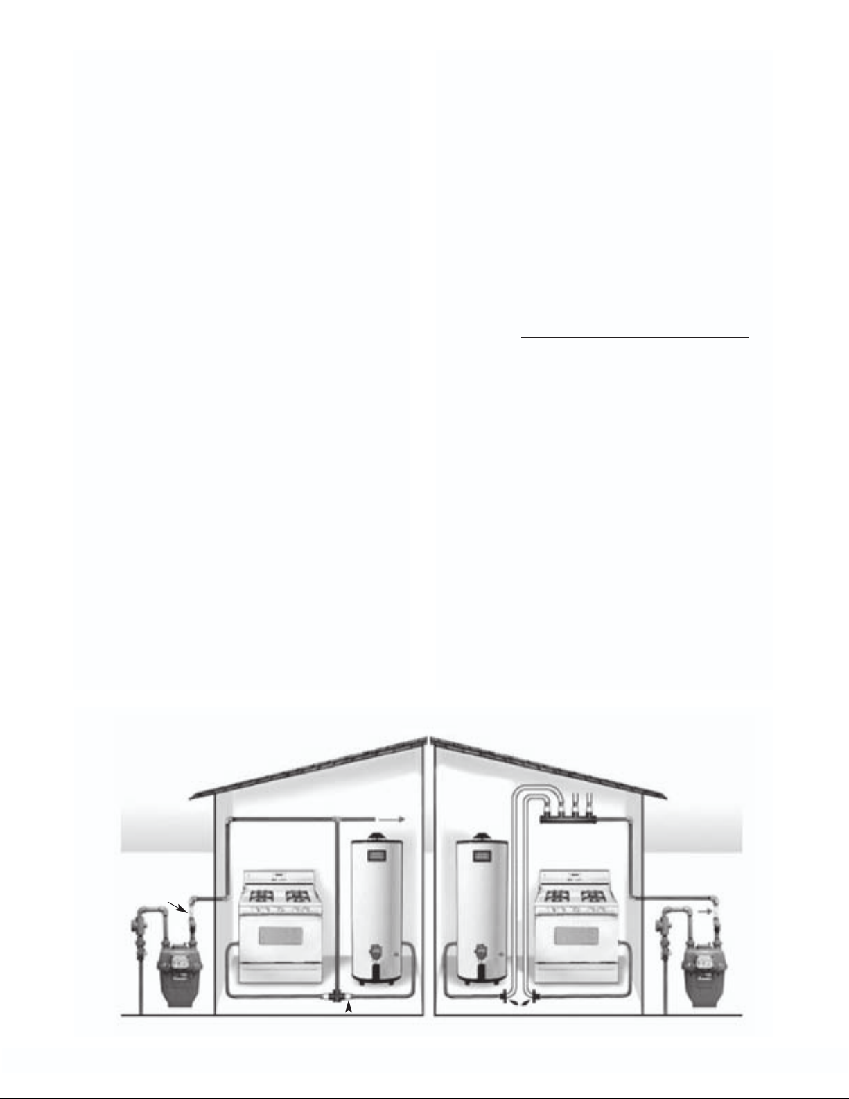
HARD PIPE SYSTEM CSST SYSTEM
(Corrugated Stainless
Steel Tubing)
GASBREAKER METER
DEVICES ARE INSTALLED
IMMEDIATELY AFTER
(DOWNSTREAM OF) THE
GASBREAKER METER
DEVICES ARE INSTALLED
IMMEDIATELY AFTER
(DOWNSTREAM OF)
THE BY-PASS TEE
GASBREAKER APPLIANCE SAFETY DEVICES ARE INSTALLED WHERE THE HARD PIPE CONNECTS TO THE APPLIANCE GAS FLEX LINES
FOR MAXIMUM PROTECTION,
ALL GAS APPLIANCES
SHOULD HAVE A GASBREAKER
SAFETY DEVICE
▲ GAS FLEX CONNECT LINE
TO OTHER
GAS APPLIANCES
CSST LINES ➤
DROP DOWN
TO GAS
APPLIANCES
CSST Termination Fittings
▲ GASBREAKER
APPLIANCE DEVICES
CONNECT TO THE
MANIFOLD IN ATTIC
or other location
▲ GAS FLEX CONNECT LINE
25
BYPASS
TEE

SECTION 3.4 — SIZING
INSTRUCTIONS FOR
GASBREAKER DEVICES USED
WITH CSST/TRACPIPE SYSTEMS
SECTION 3.4A — METER
DEVICES (SERIES FGP-GB300,
FGP-GB400, FGP-GB600)
1. Choose the GasBreaker Meter Device from
Table 3.1 based on the total capacity of the
gas piping system served by that meter.
2. Using the appropriate GasBr eaker Capacity
Chart “Table N-1GB GasBreaker Low
Pressure” or “Table N-5GB GasBreaker (2psi system)” based upon system pressure;
determine the size of CSST, which will supply the necessary total capacity of that
meter. This size of CSST is designed to
allow the GasBreaker device to act as a
safety shut-off device in the event of a complete breakage of the main downstream
trunk line piping. Note: GasBreakers
installed at the meter are not designed to
protect against breakage of piping downstream that has been reduced from the
initial size or appliance branch piping.
SECTION 3.4B — APPLIANCE
DEVICES (SERIES FGP-GB090,
FGP-GB120, FGP-GB150)
2. Series System Low Pressure
a. When there is no manifold, the devices
should be located at the tee or fitting
where the appliance drop attaches to the
trunk line. If this is a concealed location,
follow local codes.
b. Choose the appropriate size device
(“Max. Load Capacity (BTU/hr)” column)
for each appliance from Table 3.1. Select
a device with sufficient capacity to supply
the appliance(s) connected to that drop.
c. Using GasBreaker Capacity Chart “Table
N-1GB GasBreaker Low Pressure” determine size of TracPipe CSST which will
carry the required load for the distance
from the meter to the appliance(s). This
size of CSST is designed to allow the
GasBreaker device to act as a safety
shut-off device in the event of a complete
downstream breakage of pipe lines or flex
connector rupture.
SECTION 3.4C — SIZING
INSTRUCTIONS FOR GASBREAKER
DEVICES WITH STEEL PIPE
SYSTEMS
1. Choose the GasBreaker Device (Appliance
or Meter) from Table 3.1, based upon
either the capacity of the appliance or the
total capacity of the gas piping system
served by the meter.
1. Elevated Pressure 2 PSI system (Manifold
with parallel arrangement)
a. Choose the appropriate size device
(“Max. Load Capacity (BTU/hr)” column) for
each manifold outlet from Table 3.1. Select
a device with sufficient capacity to supply
the appliance(s) connected to the outlet.
b. Using GasBreaker Capacity Chart “Table
N-3GB GasBreaker Dual Pressure
System” determine size of TracPipe CSST
which will carry the required load for the
distance from the manifold to the appliance(s). This size of CSST is designed to
allow the GasBreaker device to act as a
safety shut-off device in the event of a
complete breakage of downstream pipe
lines or flex connector rupture.
2. Using GasBreaker Capacity Chart “Table
SP-1GB GasBreaker Steel Pipe Low
Pressure” determine the size of CSST,
which will supply the necessary capacity
of that appliance or meter. This size of
CSST will allow the GasBreaker device to
act as a safety shut-off device in the event
of a complete downstream breakage of
pipe lines or flex connector rupture.
Gas Breaker’s published limitations, based
upon black pipe sizing (Pipe break open to
atmosphere) are:
Series 300: For up to 60' of 3/4" and 190'
of 1" pipe.
Series 400: For up to 200' of 1 1/4" pipe
and 500' of 1 1/2" pipe.
Series 600
26
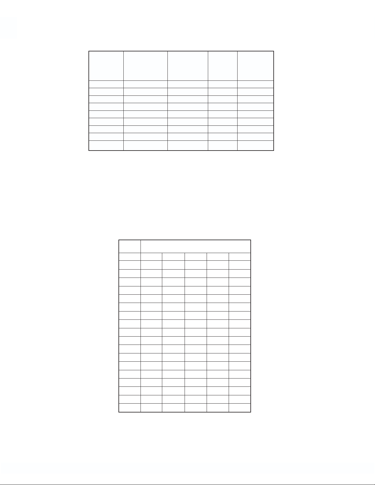
TABLE 3.1
Low Pressure Excess Flow Devices
GasBreaker Models
Valve Maximum
Inlet x Max. Load Device
Product TracPipe Outlet Capacity Closure Flow
Name Part # Male - NPT (BTU/hr) Rate (SCFH)
GasBreaker FGP-GB090-075 3/4 x 3/4 70,000 100
GasBreaker FGP-GB120-050 1/2 x 1/2"Flare 90,000 125
GasBreaker FGP-GB120-075 3/4 x 5/8"Flare 90,000 125
GasBreaker FGP-GB150-075 3/4 x 3/4 125,000 160
GasBreaker FGP-GB300-075 3/4 x 3/4 275,000 320
GasBreaker FGP-GB300-100 1 X 1 275,000 320
GasBreaker FGP-GB400-100 1 X 1 375,000 450
GasBreaker FGP-GB600-100 1 X 1 500,000 660
Notes:
1) Flow Rates given for 0.6 Specific Gravity Natural Gas with an avg. heating value of 1000 BTU / cu. ft.
2) Abbreviations: “w.c. = inches water column
SCFH = Standard Cubic Feet per Hour
3) Equivalent length pipe calculations MUST use the Maximum ⌬P across device at Trip AND the Maximum
Device Closure Flow Rate to insure that the GasBreaker EFD will act as a safety shut-off device (“Trip“ or
“Close“) under a given set of design conditions. Other ⌬P values may be found in TABLE 3.2.
TABLE 3.2
Low Pressure Excess Flow Devices
Pressure drop ⌬P(“w.c.) at Flow Rates*
FLOW GasBreaker MODEL
(SCFH) GB090 GB150 GB300 GB400 GB600
50 0.1
60 0.2 0.1
70 0.4 0.2
80 0.6 0.3
90 0.7 0.4
100 0.5 0.2
110 0.7
120 0.8
130 1.0
140 1.2
150 1.3 0.4
200 0.7 0.1 0.1
250 1.1 0.3
300 1.7 0.5 0.5
350 0.8
400 1.3 1.0
500 1.8
600 2.7
*Note: When calculating pipe lengths use TABLE 3.1 to insure
that the EFD will operate as a safety shut-off device.
27

⁄4"
1
⁄4"1" 1" 1" 1" 1
3
1
1
1
⁄4"
⁄2"
1
⁄4"1
⁄2"1
1
⁄4"1
⁄2"1
1
⁄4"1
1
⁄4"1
1
⁄2"2" 2"
1
⁄2"1
1
⁄2"1
⁄2"2"2"2"2"
1
1
⁄2"1
⁄2"1
1
1
⁄2"
⁄2"
⁄4"
⁄4"
3
3
⁄4"
⁄4"
3
3
⁄4"
⁄4"
3
3
⁄4"
⁄4"
3
3
⁄2"
⁄4"
1
3
⁄2"
⁄4"
1
3
⁄2"
⁄4"
1
3
⁄4"1" 1"1"
3
⁄4"
3
⁄4"
3
⁄4"
3
1
1
1
1
⁄2"
1
1
⁄4"1
⁄2"1
⁄2"1
1
1
⁄4"1
⁄2"1
⁄2"1
1
1
⁄4"1
⁄2"1
⁄2"1
1
1
⁄4"1
⁄2"1
1
1
⁄4"1
⁄2"1
1
1
⁄4"1
⁄4"1
1
1
⁄4"
3
⁄4"
⁄4"1"1"1" 1"1
3
3
⁄4"
⁄4"
3
3
⁄4"
⁄4"
3
3
⁄4"
⁄4"
3
3
⁄2"
⁄4"
1
3
Distance Range – Length in Feet
GasBreaker Capacity Charts
⁄2"CSST
⁄2"CSST
1
0-10 Feet <15 <20 <25 <40 <50 <60 <90 <100 <150 <200 <250 <300
1
⁄4"1"1" 1" 1"1
3
⁄4"
3
⁄4"
3
⁄4"CSST
3
⁄2"1
⁄2"1
1
1
⁄2"1
⁄2"1
1
1
⁄4"1
⁄2"1
1
1
⁄4"1
⁄2"1
1
1
⁄4"1
⁄4"1
1
1
⁄4"1
1
⁄2"2"2"2"2"2"2"
1
⁄2"1
1
⁄2"1
1
⁄2"1
1
⁄2"1
1
⁄2"1
1
⁄4"CSST 1
1
⁄4"1" 1" 1" 1" 1" 1"1
⁄4"
⁄4"
⁄4"1
1
⁄4"1
1
⁄4"1
1
⁄2"
⁄2"
1
1
1
1
1
3
⁄4"
1
3
⁄2"
⁄2"
⁄4"
1
3
⁄2"
⁄2"
⁄4"
1
3
⁄2"
⁄2"
⁄2"
1
1
3
⁄2"
⁄2"
⁄2"
1
1
3
⁄8"
⁄2"
⁄2"
1
1
3
Distance Range – Length in Feet
⁄8"
⁄8"
⁄2"
⁄4"
⁄4"1"1"1"1"1"1"1
3
3
⁄4"CSST
⁄4"CSST
3
3
0-10 Feet <15 <20 <25 <30 <40 <50 <60 <80 <90 <100 <150 <200 <250 <300
3
3
⁄8"CSST
⁄8"CSST
3
3
1
⁄2"CSST
1
P/N BTU
TracPipe Max.Capacity
FGP-GB090 70,000
FGP-GB120 90,000
FGP-GB150 125,000
FGP-GB300 275,000 1"CSST 1" 1
FGP-GB400 375,000 1"CSST 1
Meter Series
FGP-GB600 500,000 1
Appliance Series
Determine CSST size based upon the GasBreaker Device Chosen and Length of CSST Run
Table N-1GB GasBreaker-TracPipe (Low Pressure System 6-7 in w.c.)
Standard Low Pressure (6-7 in w.c.)—Pressure Drop 0.5 in w.c.
Determine CSST size based upon the GasBreaker Device Chosen and Length of CSST Run
NOTE: If you are installing a brand of CSST other than TracPipe, size each run to supply the Max Capacity of the GasBreaker device instead of the capac-
ity of appliances on that run.
Table N-3GB GasBreaker-TracPipe (Dual Pressure System-8 in w.c. -Regulator outlet @ manifold)
Regulator Outlet for 2-psi system (8 in w.c. with a Pressure Drop of 3 in w.c.)
28
P/N BTU
TracPipe Max.Capacity
FGP-GB090 70,000
Appliance Series
FGP-GB120 90,000
FGP-GB150 125,000
Meter Series
FGP-GB600 500,000 1"CSST 1" 1" 1" 1" 1
FGP-GB300 275,000
FGP-GB400 375,000
NOTE: If you are installing a brand of CSST other than TracPipe, size each run to supply the Max Capacity of the GasBreaker device instead of the capac-
ity of appliances on that run.

⁄4 "1" 1"1"
3
⁄4"
1
⁄4"1
1
⁄4"1" 1"
3
⁄4"
3
⁄4"
1
1
⁄4"1
1
1
1
1
⁄2"
⁄2"1
⁄2"2"
1
⁄4"1
⁄2"1
1
⁄4"1
⁄2"1
⁄2"2" 2" 2"
1
1
⁄4"
3
⁄4"
3
⁄4"
3
⁄4"
3
⁄4"
3
⁄2"
1
⁄2"
1
⁄2"
1
Distance Range – Length in Feet
⁄2"
1
GasBreaker Capacity Charts
⁄4"1"1"1"1"1"
3
⁄4"
3
⁄4"
3
3
⁄4"
3
3
⁄4"
3
3
⁄4"
3
3
⁄2"
1
3
⁄2"
1
3
⁄4"1"1" 1" 1" 1"1
⁄4"
⁄4"
⁄4"
⁄4"
⁄4"
⁄4"1
⁄2"1
⁄4"
⁄4"1" 1" 1" 1"
3
3
⁄4"
⁄4"
3
3
⁄4"
⁄4"
3
3
⁄4"
⁄4"
3
3
⁄4"
⁄4"
3
3
⁄2"
⁄4"
1
3
⁄2"
⁄2"
1
1
⁄2"
⁄2"
1
1
⁄2"
Distance Range – Length in Feet
⁄2"
1
1
⁄4"1"1"1" 1" 1"1
3
⁄4"
3
⁄4"
3
⁄4"
3
⁄4"
3
⁄4"
3
1
1
1
1
1
1
⁄4"1
⁄4"1
1
⁄4"1
⁄4"1
1
⁄4"1
⁄4"1
1
⁄4"1
⁄4"1
1
⁄4"1
1
⁄4"1
1
⁄2"1
1
⁄2"1
1
⁄2"1
1
⁄2"1
1
⁄4"1
1
⁄4"1
1
⁄4"1
1
⁄4"1
1
⁄4"1
1
⁄8"CSST
⁄2"CSST
0-10 Feet <25 <30 <40 <50 <75 <80 <100 <150 <200 <250 <300 <400 <500
3
1
⁄2"CSST
1
P/N BTU
TracPipe Max.Capacity
FGP-GB600 500,000
FGP-GB300 275,000
FGP-GB400 375,000
Meter Series
Determine CSST size based upon the GasBreaker Device Chosen and Length of CSST Run
Table N-5GB GasBreaker-TracPipe (2-psi system)
Meter Outlet for 2-psi system (Elevated Pressure) – Pressure Drop 1-psi
NOTE: If you are installing a brand of CSST other than TracPipe, size each run to supply the Max Capacity of the GasBreaker device instead of the capac-
ity of appliances on that run.
⁄2"Pipe
⁄2"Pipe
0-10 Feet <20 <30 <40 <50 <60 <70 <90 <100 <125 <150 <200 <250 <300
1
1
⁄2"Pipe
1
P/N BTU
TracPipe Max.Capacity
FGP-GB090 70,000
FGP-GB120 90,000
FGP-GB150 125,000
Meter Series
Appliance Series
Table SP-1GB GasBreaker Steel Pipe Low Pressure
Determine pipe size based upon the GasBreaker Device Chosen and Length of Run
Standard Low Pressure 0.5 psi or less (6-7 in w.c.)—Pressure Drop 0.5 in w.c.
29
⁄4"CSST 1" 1" 1" 1" 1
3
FGP-GB300 275,000
FGP-GB400 375,000 1"CSST 1" 1" 1
FGP-GB600 500,000 1"CSST 1
NOTE: If you are installing a brand of CSST other than TracPipe, size each run to supply the Max Capacity of the GasBreaker device instead of the capac-
ity of appliances on that run.

⁄4"
1
⁄2"
1
⁄2"1
1
Propane GasBreaker Charts
⁄4"1"1" 1" 1" 1" 1
3
⁄4"
3
⁄4"
3
⁄4"
3
⁄4"
3
⁄2"
1
1
1
1
3
3
3
⁄2"1
⁄4"1
⁄4"1
⁄4"1"1" 1" 1"1
⁄4"
⁄4"
⁄2"2" 2"
1
⁄2"1
1
⁄2"1
⁄2"2"2"2"2"
1
1
⁄2"1
⁄2"1
1
1
⁄2"1
⁄2"1
1
1
1
⁄2"1
⁄2"1
1
1
1
⁄4"1
⁄2"1
1
1
1
⁄4"1
⁄4"1
1
1
1
⁄4"1
⁄4"1
1
1
1
⁄4"1
1
1
⁄2"2"2"2"2"2"2"
⁄2"1
⁄2"1
⁄2"1
⁄2"1
⁄2"1
Distance Range – Length in Feet
GasBreaker Flow Rates in 1.55 S.G./2520 BTU/cu.ft. PROPANE
P/N Typ.Load Max Load Nom. Closing Typ.Load Max Load Nom.Closing
TracPipe Btu/hr SCFH
Table A PROPANE — GasBreaker Low Pressure Excess Flow Devices
FGP-GB090 108,880 108,880 139,988 44 44 56
Appliance Device
FGP-GB150 155,543 194,428 233,314 62 78 93
FGP-GB300 272,200 427,743 466,628 109 171 187
FGP-GB400 388,857 583,285 622,171 156 233 249
Meter Devices
FGP-GB600 466,628 777,714 933,257 187 311 373
30
0-10 Feet <15 <20 <25 <40 <50 <60 <90 <100 <150 <200 <250 <300
⁄2"CSST
⁄4"CSST
1
3
⁄4"CSST 1
1
P/N BTU
TracPipe Max.Capacity
FGP-GB090 108,880
FGP-GB150 194,428
FGP-GB300 427,743 1"CSST 1" 1
FGP-GB400 583,285 1"CSST 1
Meter Series
FGP-GB600 777,714 1
Appliance Series
Table P-1GB GasBreaker (Propane Low Pressure System 11 in w.c.)-TracPipe
Determine CSST size based upon the GasBreaker Device Chosen and Length of CSST Run
Standard Propane Low Pressure (11 in w.c.)—Pressure Drop 0.5 in w.c.

CHAPTER 4
INSTALLATION PRACTICES
SECTION 4.1 — GENERAL
INSTALLATION PRACTICES
Precautions must be taken to ensure that any
exposed flexible piping is not damaged or
abused during building construction. All system hardware should be stored in a secure,
dry location prior to installation.
1. The piping system is for use with fuel gas
at operating pressures up to 25 PSI (USA
and Canada restriction). TracPipe gas
piping (3/8" up to 1-1/4" sizes) has been
tested and is approved for pressures up to
125 PSI, and may ONLY be used at this
pressure with the consent of the local gas
utility and code authority. 1-1/2" & 2" size
TracPipe gas piping has been tested and
are approved for pressures up to 25 PSI.
Pressure tests up to 125 PSI are permitted
on sizes up to 1-1/4".
2. Only components provided by OMEGA
FLEX or specified as part of the TracPipe
piping system are to be used in the installation.
DO NOT USE TRACPIPE TUBING OR FITTINGS WITH TUBING OR FITTINGS OF ANY
OTHER MANUFACTURER. INTERMIXING OF
CSST TUBING OR FITTING COMPONENTS
BETWEEN CSST MANUFACTURERS IS
PROHIBITED. CONNECTIONS BETWEEN
TWO DIFFERENT BRANDS OF CSST MAY
BE ACCOMPLISHED USING STANDARD
MALLEABLE IRON FITTINGS.
3. Ends of the piping are to be temporarily
capped, plugged or taped closed prior to
installation and pulling through structure to
prevent entrance of dirt, or other debris.
4. Contact with sharp objects or harmful substances is to be avoided. Contact with
any chemicals containing chlorides or
ammonia must be followed by thorough
rinse and wipe dry.Typical chloride based
chemicals include fluxes used for soldering copper tubes and acid based cleaners
such as muriatic acid used for cleaning
brickwork. Use only non-cor
detection fluids.
5. BENDING TRACPIPE
Undue stress or strain
on the tubing or fittings is to be avoided.
Bending flexible gas
piping is one feature
which contributes to
the speed of installation. The recommended bend radius for general routing of tubing is listed in Table 4-1. Multiple tight
bends can restrict the gas flow and
increase pressure drop. The tightest bend
allowed for each size of TracPipe is
shown in the chart below. Typical locations
rosive leak
Figure 4-1
RECOMMENDED MINIMUM BENDING RADIUS FOR FLEXIBLE GAS PIPING
Table 4-1
TUBING SIZE ABSOLUTE MINIMUM RECOMMENDED MINIMUM
BEND RADIUS R BEND RADIUS R
3/8 inch 9/16 inch 3 inches
1/2 inch 3/4 inch 3 inches
3/4 inch 1 inch 3 inches
1 inch 3 inches 5 inches
1-1/4 inch 3 inches 5 inches
1-1/2 inch 3 inches 5 inches
2 inch 4 inches 6 inches
31

requiring tight bends are termination mount
installations in hollow stud walls.
6. SUPPORTING TRACPIPE
Piping shall be supported in a workmanlike manner with pipe straps, bands,
brackets or hangers suitable for the size
and weight of the piping. TracPipe
which passes over or through a structural
member is considered to be supported
by that member.
6A. VERTICAL RUNS
Spacing of supports is not to exceed 10
feet, requiring hangers only where the
height of each floor is greater than 10 feet.
HORIZONTAL OR INCLINED RUNS
PIPING SIZE SPACING OF SUPPORTS
3/8 inch 4 FEET
1/2 inch 6 FEET
3/4 inch 8 FT. (USA) 6 FT. (CANADA)
1 inch 8 FT. (USA) 6 FT. (CANADA)
1-1/4 inch 8 FT. (USA) 6 FT. (CANADA)
1-1/2 inch 8 FT. (USA) 6 FT. (CANADA)
6B. HORIZONTAL RUNS
Spacing of supports Hangers, supports
and anchors-Piping shall be supported
at intervals not to exceed those shown in
Table 4-2. It is acceptable to use standard
pipe straps or tubing clips available in
metal or plastic materials, OMEGAFLEX
has found that the use of two-attachment
point plastic clips or metal EMT pipe
straps is advisable.
Some plastic clips, especially the “Jclips” designed to support plastic tubing
are susceptible to breakage upon subsequent handling by other trades.
Table 4-2
2 inch 8 FT. (USA) 6 FT. (CANADA)
32

SECTION 4.2
HOW TO ASSEMBLE TracPipe AUTO-FLARE FITTINGS
INSTRUCTIONS for making Fitting Connections to Flexible Gas Piping
1. CUT-TO-LENGTH: Determine proper
length. Cut through plastic jacket and stainless tube using a tube cutter with a sharp
wheel. Cut must be centered between two
corrugations. Use full circular strokes in one
direction and tighten roller pressure slightly
(a quarter turn) after each revolution. DO
NOT OVERTIGHTEN ROLLER, which may
flatten tube.
NOTE: Due to the large diameter and depth of corrugation on sizes over 1", tubing must be cut with
a standard tubing cutter RIDGID
using a TracPipe cutting wheel no. FGP-E-5272
(P/N E-5272 or equal). CAUTION: Use of a small cutting wheel may flatten the first corrugation and
make cutting and/or sealing of fittings difficult.
TM
152 or equal
2. STRIP JACKET: Using a utility knife, strip
back the jacket approximately one inch to
allow assembly of fittings. Caution: For your
personnal safety--Knife blade and cut tube ends
are both sharp. Use care when cutting the jacket and handling the tube.
33

INSTRUCTIONS for making Fitting Connections to Flexible Gas Piping
(Continued)
3. INSTALL FITTING NUT: Slide nut over cut
end: place two split-rings into the first
corrugation next to the tube cut. Slide
nut forward to trap the rings.
4. WRENCH FITTING: Place the adapter into
the nut and engage threads. Note that the
AutoFlare
leak tight seat on the stainless tubing
as you tighten the fitting. (The piloting feature of the adapter will not always enter
the bore of the tubing before the tightening operation, but will center the fitting when tightened). Using appropriate
wrenches, tighten the fitting until adapter
bottoms and the resistance to wrenching
increases greatly. The flare has now been
created on the tubing end.
CAUTION- DO NOT USE ANY THREAD
SEALANTS FOR THIS CONNECTION.
SEALANTS ARE TO BE USED ON THE PIPE
THREAD ONLY.
Flexible Pipe Size Fitting Torque Value
3/8" FGP-SS4-375 FGP-FST-375 40 ft.-lb.
1/2" FGP-SS4-500 FGP-FST-500 42 ft.-lb.
3/4" FGP-SS4-750 FGP-FST-750 45 ft.-lb.
1" FGP-SS4-1000 FGP-FST-1000 75 ft.-lb.
1-1/4" FGP-SS4-1250 FGP-FST-1250 150-200 ft.-lb.
1-1/2" FGP-SS4-1500 FGP-FST-1500 200-250 ft.-lb.
®
fitting is designed to form a
Table 4-3
5. FINAL TORQUE: Tighten nut and adapter
to the torque values shown in Table 4-3.
For field installations use the following
method: Tighten nut and adaptor as
though you were making up a flared tubing
joint. Note relation between hex flats at
this point and continue to tighten for two
additional hex flats (one-third turn) to
obtain required torque and final leak-tight
seal.
2" FGP-SS4-2000 FGP-FST-2000 250-300 ft.-lb.
34

AutoFlare® (Patented) – The Fitting is the Flaring Tool
SECTION 4.2A — TROUBLE SHOOTING
FITTING CONNECTIONS
1. The tubing cut is the critical step in the
fitup procedure. Always cut in a straight
section of piping, rather than an area you
have bent. Use light roller pressure applied
on every revolution to cut tube evenly
around its surface. Remember that this
tube has a thinner wall than the copper
tube you are accustomed to cutting. A
sharp blade is very important, and it will be
helpful to reserve one cutter for stainless
steel only.
2. If the fitting connection cannot be made to
seal upon applying torque per the instructions in Section 4.2, continue to tighten an
additional quarter to a half turn. If leakage
continues, do not continue to apply
torque. Disassemble the fitting and
inspect the sealing surfaces. The most
likely cause of leakage is foreign material
on the sealing surfaces. Wipe both fitting
and tubing flare with a clean cloth.
Inspect the formed flare on the tubing
end, which should appear round when
compared with the split ring washers and
the nut in place. If any deformation is
noted, the tubing can be recut and the fitting re-attached. The patented Autoflare
fitting has an insert which is self piloting
and does not require special tooling to make a
leak proof fitting.
3. REASSEMBLY - When reattaching the
AutoFlare fitting, it is only necessary to reinsert the split rings into the space
between the first two corrugations and to
pull the nut back over the rings into position. The adapter can then be conveniently re-threaded into the nut and torqued as
before. If the nut cannot be pulled into
place, examine the split-rings, which may
have been “coined” by the first torque
operation. If this is the case, simply
reverse the split-rings positioning to align
with the nut and continue the assembly
pr
ocess.
three times, or if the nut cannot be pulled over
the rings in any position, then the split-rings
must be replaced. Packets of spare split-
rings are available (P/N FGP-RING-SIZE)
and the remaining fitting parts can be reused.
If the fitting is reattached more than
35

SECTION 4.3 — ROUTING
Depending on local building codes and construction practice, Flexible gas piping can be
routed:
1. Beneath floor joists, thr
ing joists, along side of floor and ceiling
joists. This is the typical location for residences and commercial buildings with
basements and for multi-floor systems.
2. Inside hollow interior wall cavities.
the preferred location for vertical sections
of piping, rather than horizontal sections.
3. Thr
4. Clearance holes for routing the piping
ough approved conduit under ground
or under building slabs. When piping runs
are located below grade or under a concrete slab, the TracPipe shall be routed
within a non-metallic water-tight conduit.
No tubing joints are permitted within the
conduit. Gas piping runs beneath building
slabs must be both sleeved and vented
to the atmosphere. See Underground
Installations Section 4.9 for underground
use of TracPipe PS and TracPipePS-II.
TracPipe PS and TracPipePS-II meet
code requirements for underground and
under building slab installation.
through studs, joists, plates etc. shall have a
diameter at least 1/2 inch larger than the
outside diameter of the piping. When a
structural member must be drilled, conformance to building codes must be followed.
No structural member shall be seriously
weakened or impaired by cutting, notching
or otherwise altering the member. Minimum
drill hole sizes are listed in Table 4-4.
Table 4-4
TUBING SIZE DRILL HOLE SIZE
3/8 inch 1-1/8 inch
1/2 inch 1-3/8 inch
3/4 inch 1-1/2 inch
1 inch 1-3/4 inch
1-1/4 inch 2-1/4 inch
1-1/2 inch 2-1/2 inch
2 inch 3 inch
ough floor and ceil-
This is
5. METAL STUDS
For installations involving horizontal runs
through galvanized steel studs, the use of
plastic grommets supplied by the stud
manufacturer is recommended. The use of
these grommets will reduce the likelihood
of damage to the tubing non-metallic
jacket.
SECTION 4.3A — CONCEALED
LOCATIONS FOR FITTINGS —
GENERAL PROVISIONS
The AutoFlare®mechanical attachment fittings have been tested and are listed per the
requirements of ANSI LC1 and CSA 6.26
Standard (USA and CANADA) This specification provides test requirements which certify
fittings for concealed installations and connections to appliances where concealing the
fittings is the only practical alternative.
These guidelines address some of the known
situations which may require the use of a concealed fitting. While accessibility of fittings may
be desirable there are often situations where
concealing the fittings is the only practical
option. This guide cannot address all applications of concealed fittings but provides instead
typical instructions to demonstrate the principles which apply to fittings listed for installation
in concealed locations (Ref National Fuel Gas
Code NFPA54 Chapter 6).
EXCLUSIONS:
1. Manifold Stations (for 2 PSI systems)
which include the multiport manifold, shut
off valve, and pressure regulator shall not
be installed in concealed locations
regardless of the qualifications of tubing
fittings.
NEW INSTALLATIONS:
1. CSST may be connected to steel piping
systems through threaded pipe connections.
This can be a stub-out to an appliance connection or outdoors to a meter, etc.
2. Flexible piping connections to fireplace
“key valves” can be located in a concealed
location, when accessibility is not readily
36
36

provided. See Illustrations 1 & 2 for typical
key valve mountings.
GLOBE KEY VALVE
AUTOFLARE
FITTING
(ON INLET AND OUTLET)
C-CLAMPS
FOR SUPPORT
MOUNTING STUB
Illustration 1
Key Valve
Bracket
Assy.
TRACPIPE
GAS TUBING
(ON INLET AND OUTLET)
Flexible piping fittings originally installed in
accessible ceiling locations can be concealed at a later date in the event that a
ceiling is installed. Precautions shall be
taken to ensure that the newly concealed
piping and fittings are adequately protected from accidental puncture in accordance
with the instructions in this guideline.
2. Extensions to existing tubing runs-A tubing run
can be modified to permit an extension to
another appliance location provided there is
sufficient capacity to supply both appliances at the same time. If an accessible
location for the modification is not available,
the existing tubing run can be modified with
a tee fitting, resulting in a concealed fitting.
3. Repairs to existing tubing runs-Damaged tubing
runs shall be repaired in accordance with
instructions in this guide (Section 5.2). The
repair can result in a line splice which may
ultimately be located in a concealed location.
Outlet to fireplace
use TracPipe or
rigid pipe
Illustration 2
3. Multiple gas outlets – when multiple outlets are supplied from a single run of piping, each downstream outlet branch can
be connected to the main run using a tee
fitting which can be located in a concealed
location.
Figure 4-2 Multiple outlets along main tubing run
MODIFICATIONS TO INSTALLED
SYSTEMS:
1. New ceilings in unfinished rooms/basements-
SECTION 4.3B — OUTDOOR
INSTALLATION ISSUES
The following section provides instructions
for the use of TracPipe in systems in which
portions of the piping are exposed to the outdoors as required to make connections to
gas meters or appliances which are attached
to, mounted on, or located in close proximity
to the building structure. ANSI/IAS LCICSA 6-26-1997 contains test requirements
determining suitability for exposure of
CSST piping systems to outdoor environments. T racPipe is certified to this standard
and is fully qualified for outdoor installations.
The TracPipe yellow jacket contains UV
inhibiters to retard jacket degradation when
exposed to long periods of sunlight.
1. When installed outdoors, the plastic jacketing shall remain intact as much as practical for the given installation. Any portions
of exposed stainless steel shall be
wrapped with self bonding silicone tape
sealing the fitting connection to prevent
later corrosive attack by acid wash or
chloride based compounds. (See Figures
4-3A & 4-3B)
37

2. When TracPipe is installed in a swimming
pool mechanical room or exposed to a corrosive environment which may be harmful to
the tubing, all exposed portions of the stainless steel tubing shall be wrapped with selfbonding tape. (See Figures 4-3A & 4-3B)
3. When installed along the side of a structure
(between the ground and a height of 6 feet)
in an exposed condition, the TracPipe
shall be installed in a location which will not
subject the piping to mechanical damage
or be protected inside a conduit.
NOTE: For support and protection, OmegaFlex recommends that outside runs along the side of a building be
clipped securely to the wall or other structural component.
4. TracPipe shall not be buried directly in
the ground or embedded in concrete
unless it is sleeved inside of a non-metallic (PVC or TracPipe PS or PS-II
Polyethylene) water tight conduit. The
conduit shall be sealed at any exposed
end to prevent water from entering. See
instructions for underground installations
Section 4.9.
5. When installed underneath mobile homes
or in crawl spaces, TracPipe shall be
installed in accordance with these standard outdoor instructions.
SECTION 4.4 — PROTECTION
The flexible gas piping must be adequately
protected from puncture, shear, crush or
other physical damage threats. The tubing
shall be protected at points of support and
when passing through structural members
such as studs, joists and plates in accordance with this section. PROTECTION IS
REQUIRED WHENEVER THE TUBING IS
CONCEALED, RESTRAINED, AND WITHIN 3
INCHES OF A POTENTIAL THREAT. If the
tubing requires protection, the following
measures should be taken.
SECTION 4.4A —
STRIKER PLATE REQUIREMENTS
1. Install shielding devices i.e. striker plates to
protect the tubing from penetration by drill
bits, nails, screws, etc. in those areas where
the tubing will be concealed and will not be
free to move to avoid such puncture threats.
NOTE: Only CSA approved hardened striker plates
listed for CSST systems may be used.
a. At support points and points of penetra-
tion less than 2 inches away from any
edge of a stud, joist, plate, etc. shielding
is required at the area of support and
within 5 inches of each side (if appropriate). Use a half striker or a full striker
plate in these locations. (Figure 4-4)
Figure 4-3A Wrapping with self bonding
silicone tape - begin on jacket.
Figure 4-3B Wrapping with self bonding
silicone tape - end on nut.
Figure 4-4
Long Unsupported
Tubing Runs
(over 3') within
a Wall Partition.
38

b. At support points and points of penetration 2
to 3 inches from any edge of stud, joist plate,
etc. shielding is required throughout area of
support. Use a quarter striker plate in these
locations. (Figure 4-5)
Figure 4-5
Shielding Requirements at Support Area when Points of Penetration
are 2-3 inches from any Edge of a Stud, Joist, Plate, etc.
include: (but are not limited to) outside walls
of buildings with sheathing in place, between
floors with enclosed joist areas, and retrofits
in existing buildings with walls in place. Steel
pipe having an inner diameter at least one-
c. Hardened steel striker plates provide the
required protection through building structures as described above. Type RW Floppy
steel conduit shall be installed as additional
protection at termination points. (Figure 4-7)
Typical Wall Stud
3-1/2"
Interior Wall
Less than 2"
(Wood or Metal)
Termination
Outlet (Stud
Mounted)
Stripwound
Metal Hose
Striker Plate
half inch larger than the TracPipe O.D. is
approved by CSA International for this use as
an alternate to striker plates. Protection must
extend 5 inches beyond the penetration of
the structural member(s). A 12 inch pipe
length is appropriate for penetration of a single stud. Omegaflex recommends the use of
standard striker plates where the building
construction permits their installation. See
Chart for pipe sizes.
TracPipe Size Steel PipeSize
3/8 inch 1-1/4 inch
1/2 inch 1-1/4 inch
3/4 inch 1-1/2 inch
1 inch 2 inch
1-1/4 inch 2-1/2 inch
1-1/2 inch 2-1/2 inch
2 inch 3-1/2 inch
Figure 4-7
d. When tubing is routed horizontally
between studs, install quarter striker
plates at each stud and floppy galvanized
steel conduit (spiral metal hose) along the
entire length.
e. Schedule 40 steel pipe has been tested by
CSA International and found acceptable for
puncture protection. Steel pipe can be used
where standard striker plates cannot reasonably be installed. Examples of this type of use
2. The best protection is to install the tubing
in those out of the way areas where
testing has shown no protection is necessary, for example:
a. Where the tubing is supported more
than 3 inches from any outside edge of
a stud, joist, plate, etc. or wall surface.
(Figure 4-6)
b. Where any non-restrained tubing can be
displaced from the direction of potential
penetration at least 3 inches.
39

Figure 4-6
No Shielding Requirement at Support Area when Points of
Penetration are greater than 3 inches from any Edge of a Stud,
Joist, Plate, etc.
c. When tubing is supported under the
joists in basements or crawl spaces
and is not concealed by wallboard or
ceilings.
3. TracPipe with its specially formulated yel-
low polyethylene jacket has been tested to
the flame spread and smoke density
requirements of ASTM E84 and meets
ANSI LC-1 limits imposed for this criteria.
NOTE: For TracPipe tubing version with Black
outer jacket, the installer shall meet local building
codes with respect to flame spread and smoke density regulations for non-metallic materials.
Omegaflex recommends either removing the black
jacket or transitioning to the standard yellow jacketed product when passing through areas such as
drop ceiling return plenums.
4. For through-penetration fire stop instructions refer to the UL classification requirements shown in appendix A. When passing
through a fire stop (2hr. wall) the YELLOW
jacket does not have to be r
emoved. Seal
between building and TracPipe with an
approved 3M type CP-25 or equivalent
caulk. The BLACK jacket shall be removed
for 2 ft. on each side of the penetration
when passing through a fire stop.
5. TracPipe has thru-penetration UL
Classifications for 1,2,3 and 4 hour
requirements depending on materials and
type of construction. See Appendix A.
40

SECTION 4.5 —
METER CONNECTIONS
1. Meters which depend on the service and
house piping for support shall not be
directly connected to the flexible piping.
Instead, use a meter termination fitting or
termination mount fitting with steel pipe for
the outdoor portion of the connection. For
mounting of meters, all fastener locations
should be used when installing the flange or
mounting plate. (Figure 4-8)
2. Meters which are independently supported
with a bracket can be directly connected outdoors with TracPipe. If practical, direct con-
nections shall include a 3 to 6 inch additional
length of tubing to accommodate differential
settling and meter movement. No mechanical protection of the tubing is required for outdoor connections. PRIOR TO INSTALLING
TracPipe DIRECTLY TO A METER,
ENSURE THAT THE LOCAL UTILITY
ALLOWS THIS PRACTICE as some utilities
have regulations specifying meter attachments. Any exposed sections of stainless
steel piping must be wrapped with a silicone self-bonding tape.This is especially
important with masonry construction.
(Figure 4-9) A PVC Sleeve is recommended for TracPipe penetration of both
masonry and wood frame construction.
Figure 4-9
Meter Mount
(Surface mount on sheathing
or through the rim joist.)
Termination Mount
(Mount on one stud.)
Note: Diameter of hole shall be at
least 1/2" greater than O.D. of tubing and shall be sleeved and/or
sealed in accordance with local
building code (if applicable).
Figure 4-8
Use a meter
termination or
a termination
mount here
Stud Bracket
(Mount between two studs.)
Figure 4-10
Meter Mounting Accessories
41

SECTION 4.6 — APPLIANCE
CONNECTIONS
A listed termination outlet (termination mount or
flange fitting) shall be installed and secured to the
structure at all floor & hollow wall piping outlets
used for moveable appliances and quick disconnect devices. The termination outlets are
designed to simplify the installation of gas connections for movable appliances and minimize
the need for concealed fittings. The flange fitting
or plate shall be securely fastened in place during
rough-in. It may be attached to a brace spanning
between studs for a wall location, or directly to
the floor. (Figure 4-11) The flange may also be
mounted with a flange L- bracket, which is nailed
or screwed to the stud.
When a moveable appliance is in a location where
a termination outlet cannot be readily installed
through the structure, the TracPipe can be tran-
sitioned to black pipe at a suitable location and
the black iron pipe fastened to the block walls or
concrete. Another option is to use termination
mounting bracket fastened to the block wall and
make the drop with TracPipe. Final connection
is with a flexible appliance connector.
1. MOVABLE APPLIANCE CONNECTIONS
(SUCH AS RANGES AND DRYERS) SHALL
BE MADE USING APPROVED FLEXIBLE
APPLIANCE CONNECTORS.
(Figure 4-12)
See also recessed wall box
2. FIXED APPLIANCE CONNECTIONS MAY BE
DIRECTLY CONNECTED TO THE FLEXIBLE
GAS PIPING SYSTEMS (in most jurisdictions).
When the fixed appliance is located in a
secure, dedicated space, such as a basement, attic, garage or utility closet, the flexible
piping may be directly connected to the appliance shut-off valve without installation of a
flange fitting or flexible appliance connector.
Section 4.6-3.
Figure 4-11
Support Device Flange Termination Outlet
Interior Wall
Stripwound
3-1/2"
Metal Hose
Termination
Outlet
Protected
Area
Typical Wall Stud
(Wood or Metal)
6"
Figure 4-12
Stainless Steel Gas Connector Connection to a Movable Gas Appliance
42

3. RECESSED WALL BOX
TracPipe Part Number FGP-WBT-500
Product Description: TracPipe Recessed
Wall Box makes possible appliance stub
outs with zero clearance for a finished
appearance in laundry rooms, kitchens and
mechanical rooms. This accessory provides
a rigid attachment point for appliance connectors serving movable appliances.
3A. Wall Box Installation Instructions
1. Install TracPipe gas pipe and cut to
desired length using a tubing cutter with
sharp wheel. Strip yellow jacket back
approximately 2". Inspect pipe for a
clean cut without tears.
Caution: This is not a fire rated box.
Before installing on a fire wall, consult
your local code authority for acceptable
installation practices. This box has been
designed for use with TracPipe Flexible
Gas Piping as an appliance termination
and is not suitable for connection to any
other CSST brand or black iron pipe.
Installers must be trained on TracPipe
before installing this product.
2. Remove box cover and slip locknut and
box over end of pipe.
BOX COVER
VALVE NUT SPLIT LOCKNUT
RINGS
43

3. Disassemble valve and split rings from
nut.
4. Slip nut over end of pipe and insert split
rings into valley of the first corrugation.
6. Slide box up and over the threads on the
bottom of the nut and mount box to stud.
7. Secure valve assembly to box with locknut.
5. Thread 90 degree ball valve onto nut and
tighten so valve outlet faces forward. It is
recommended that crescent wrenches
be used to avoid damaging valve or nut.
Do not use thr
connection.
ead sealants on this
8. Install box cover after completion of drywall.
44

SECTION 4.6A — P AD MOUNTED
EQUIPMENT, ROOF TOP EQUIPMENT
Table 4-2, and raised above the roof a distance determined by local code/practice.
1. Gas appliances mounted on concrete
pads or blocks, such as gas air conditioners heat pumps, pool heaters and NGV
refueling stations, shall be connected to
the TracPipe system at a termination fit-
ting using either rigid pipe or an approved
outdoor appliance connector. Direct connection of TracPipe to pad mounted
equipment is permitted when the CSST is
securely supported and located where it
will be protected from physical damage.
Follow local and state codes.
3. TracPipe may be supported with
strut/channel running from block to block
beneath the flexible gas pipe. Galvanized
shallow channel (13/16") with splice plates
at joints and bends provides a secure,
damage resistant “track”. With metallic
strut support, blocks can be reduced to
every 8 feet. The TracPipe should be firm-
ly attached to each block with metallic
clamps designed for the strut or appropriate fastening mechanism. (See Figure 4-
15) Black cable ties (UV resistant) at intermediate points facilitate rolling out the
TracPipe. The blocks are to be attached
to the roof surface in accordance with the
roofing manufacturer’s instructions.
Figure 4-13 Short (1-6 foot) outdoor
connection to roof mounted equipment
2. No special mechanical protection of the
piping is required for connection to roof
top equipment. Whenever possible, roof
penetrations shall be located within 6 feet
of the equipment to be connected as
shown in figure 4-13. Long runs of tubing
shall be supported with non-metallic
blocks at the support interval listed in
TYPICAL:
NON-METALLIC TUBING SUPPORT
SPACING PER TABLE 4-2
*TUBING ELEVATED
4-6" TYP. ABOVE ROOF
STANDARD ROOF
PENETRATION
TUBING CLIP
CSST
*HEIGHT OF ELEVATION BASED ON LOCAL PLUMBING/BUILDING
CODE REQUIREMENTS AND/OR WINTER ICE BUILDUP.
Figure 4-15
4. Piping run vertically up the side of the
building shall be protected in accordance
with the General Provisions section of the
outdoor use guidelines (section 4.3B).
GAS
SHUT-OFF VALVE UNION
HUNG CEILING
APPLIANCE
Figure 4-14
45

SECTION 4.6B — OUTDOOR
APPLIANCES — BARBEQUE GRILL
AND GAS LIGHT CONNECTIONS
1. Movable Grills shall be connected using an
approved outdoor appliance connector
which shall be attached to the flexible piping system at either a termination mount
fitting, a transition to a steel nipple, or a
quick -connect device such as the M. B.
Sturgis Model 3/375 shown in figure 4-16.
The quick-connect outlet shall be installed
in accordance with manufacturer’s instructions.
2. Permanently mounted grills located on
decks shall be connected with the
TracPipe system as shown in figure 4-17
and in accordance with this guide. The
outdoor portion of the piping shall be supported against the side of any of the inside
deck joists. If the elevation of the deck is
below the top of the foundation, any
exposed piping shall be protected using
water-tight non-metallic conduit.
3. Permanently mounted lights located on
decks shall be connected to the piping system the same as permanently mounted
grills shown in figure 4-17 and in accordance with the manufacturer’s instructions.
Figure 4-17
4. Yard mounted lights shall be connected to
the TracPipe system as shown in figure 4-
18. All piping installed below grade shall be
protected by non-metallic, water-tight conduit or TracPipe PS or TracPipe PS-II
for underground use. Exposed ends of the
conduit shall be sealed against water entry.
Figure 4-16
Figure 4-18
46

Section 4.6C — FIREPLACE
INSTALLATIONS
1. TracPipe may be used to deliver gas
directly to the valve for a gas fireplace.
This is approved for decorative and heat
generating fireplaces and for gas logs
used in masonry and pre-fabricated fireplaces. DO NOT use TracPipe to con-
nect gas log lighters or gas wands for use
in all-fuel (woodburning) fireplaces.
2. Most gas fireplaces and gas logs (Refer to
ANSI Z24.60) fall into the definition of
fixed appliances which can be directly
connected to TracPipe without the use of
a flange mount fitting. The attachment is
generally to the shut-off valve which may
be located in the control area beneath the
burner unit or at the side of the log set.
TracPipe can be run into the lower control area for attachment without removal
of the polyethylene jacket. In vented fireplaces, attachment to gas logs is best
accomplished by removal of the jacket
inside the fire box. This precludes direct
flame contact with the polyethylene jacket. Stainless Steel melting temperatures
o
(2000
F) are consistent with black iron.
4. When it is necessary to install TracPipe
through sheet metal enclosures, such as
those commonly used in decorative gas
fireplaces, the manufacturer’s recommendation is to leave the protective yellow
polyethylene jacket in place through the
sheet metal penetration. The TracPipe
should be clipped to the building structure
at a suitable location outside the fireplace
to limit the amount of motion after installation. If additional protection is required,
such as an installation with a source of
vibration (fan, etc.) which may cause
abrasion, then a short piece of floppy
conduit or PVC pipe may be used
between the jacket and the enclosure.
5. In masonry fireplace installations of decorative gas appliances (log sets) it is recommended to leave the polyethylene
jacket in place throughout the masonry
penetration providing a non-metallic
sleeve for the flexible stainless steel.
Caulking can then take place between the
jacket and the penetration at interior
and/or exterior locations. Remove the
jacket inside the firebox. If additional protection is required, the TracPipe may be
sleeved using PVC pipe in addition to the
included jacket.
3. For gas log lighter installations in all-fuel
fireplaces, the TracPipe run MUST be
terminated at the key valve or another
location outside the fireplace. The final
attachment should be made using black
iron pipe.
MASONRY FIREPLACE
T racPipe
through
stud
walls
TracPipe through basement or
TracPipe through basement or
crawl space
crawl space
Figure 4-23 Figure 4-24
Sleeve if
required
6. The FGP-FPT may be used in all applications where it is desirable not to penetrate
the enclosure with tubing. (See figure 4-
24)
METAL FABRICATED FIREPLACE
Key V
alve Bracket
FGP-KVB-500
or
FGP-KVB-750-500
(Opt.)
Stub Out
FGP-FPT-500 (Opt.)
TracPipe
47

elevated pressure
from gas meter
line shut-off
approved valve
vent limiter
low pressure
to appliances
AutoFlare fittings
house line
dirt trap pocket
per code
regulator
SECTION 4.7 — MANIFOLD &
REGULATOR STATION
The use of a central manifold and regulator
station is recommended for elevated pressure systems which are typically installed in a
parallel arrangement to take advantage of the
capacity of the regulator, which is sufficient
for several appliances. Manifolds are available with the TracPipe system, or the use of
black iron pipe and tee fabricated manifolds
is permitted with this system. The manifold/regulator station should be located nearby the largest gas consuming appliances,
typically the furnace or boiler and the water
heater in order to allow short runs to these
units.
union
manifold
The manifold station MUST be located in an
accessible location because of the shut-off
valve(s) and regulator it contains. The manifold station may be contained in an enclosure
box called a gas load center. Optional gas
shut-off valves may be mounted on the manifold for each appliance run.
Gas Load Center
48

SECTION 4.8— REGULATORS
AND ELEVATED PRESSURE
SYSTEMS
A tubing system used at gas pressures
exceeding 1/2 PSI but serving appliances
rated for 1/2 PSI maximum, shall contain a
pounds-to-inches regulator to limit the downstream pressure to no more than 1/2 PSI. The
regulator must incorporate a lock-up feature
limiting downstream pressure to 1/2 PSI
under no flow conditions. The regulator shall
comply with the applicable provisions of ANSI
Z21.18 or CAN 1-6.3-M82.-ANSI Z21.80
Regulators used to reduce elevated system
pressures for use by appliances must also
conform to the following:
1. Must be sized to supply the required appliance load.(see chart below)
Capacities and Pressure Drop
Nat. Gas 0.64 Specific Gravity
Pressure Drop through Regulator
P/N 7" w.c. 1/2 psi 3/4 psi 1psi
FGP-REG-3
FGP-REG-5A
FGP-REG-7L
2. Must be equipped with an acceptable vent
limiting device, supplied by the manufacturer, or be capable of being vented to the
outdoors. The vent-limiting device can be
used when the regulator is installed in a
ventilated area. OMEGAFLEX ships all
REG-3 & REG-5A regulators with vent-limiters installed. Vent-limiters are not available for REG-7 series regulators.
145 204 250 289
338 476 583 673
690 972 1191 1375
TIONS. WHEN A VENT-LIMITER IS USED
THE REGULATOR MUST BE MOUNTED
IN AN UPRIGHT POSITION. INSTALL THE
REGULATOR PROPERLY WITH GAS
FLOWING AS INDICATED BY THE
ARROW ON THE CASTING.
4. Must be installed in a fully accessible area
with an approved shut off valve ahead of
regulator. An optional union will enable
removal of the regulator if the location
does not otherwise permit removal for servicing. The ability of the autoflare fitting to
allow dissasembly and reattachment provides for regulator removal in most
instances.
5. Line regulators do not vent gas under normal
operating conditions. Any regulator found to
be venting gas should be replaced immediately. Vent-limiters are required to limit venting in the event of a diaphram failure, within
the regulator, to limits identical to those
imposed on a gas appliance control valve.
6. An area is considered to be ventilated if the
combustion, ventilation or dilution air is
obtained from the occupied areas of the
building, or from outside, or from both, into
the common areas of the appliance locations.
Reference applicable codebook for details.
7. For outdoor installations remove the vent
limiter and mount regulator with the vent
outlet pointing down to prevent the
entrance of water. A plastic cap FGP-CAP-3
is available for outdoor installations permitting regulator to be mounted in an
upright position.
NOTE: For outdoor venting, the line must be
at least the same size as the regulator vent
connection, and cannot exceed a length of
30 feet. The vent shall be designed to prevent entry of water, insects or other foreign
materials that could cause blockage of the
line. DO NOT VENT TO APPLIANCE FLUE
OR BUILDING EXHAUST SYSTEM. DO NOT
VENT TO PILOT LIGHT.
3. MUST BE INSTALLED IN ACCORDANCE
WITH MANUFACTURERS INSTRUC-
SECTION 4.8A REGULATOR
ADJUSTMENTS
1. Regulators can be adjusted to deliver different outlet pressures within a limited
range. The range is determined by the
spring installed.
2. Adjustment can be accomplished by first
removing the regulator seal cap to expose
the adjusting screw . Turning the screw clock-
49

wise will increase outlet pressure, turning it
counter-clockwise will decrease pressure.
3. If spring adjustment will not produce
desired outlet pressure, check to make
sure supply pressure is at least equal to
desired outlet pressure plus pressure drop
of the regulator. If supply pressure is ade-
quate, consult factory if adjustment still can
not be made. Do not continue to turn regulator adjusting screw clockwise if outlet
pressure readings do not continue to
increase. THIS MAY RESUL T IN OVER-FIRING DUE TO LOSS OF PRESSURE CONTROL, SHOULD THERE BE A SUBSEQUENT INCREASE IN INLET PRESSURE.
APPLIANCE
PRESSURE
SECTION 4.8B — REGULATOR CAPACITIES AND PRESSURE
DROP FOR MULTIPLE APPLIANCES
Natural Gas 0.64 Specific Gravity
1. PRESSURE DROP ACROSS 2 PSI REGULATOR: expressed in CFH (m3/h) (0.64 Specific Gravity Gas)
Part Number
FGP-REG-3
FGP-REG-3P
FGP-REG-5A
FGP-REG-5P
FGP-REG-7L
NPT
SIZE
1/2"
3/4"
1-1/4"
Maximum Individual Load:
FGP-REG-3 OR -3P OR -3X 140 CFH
FGP-REG-5A OR -5P OR -5AX 300 CFH
FGP-REG-7L 900 CFH
2. PRESSURE DROP ACROSS 5 PSI REGULATOR: expressed in CFH (m3/h) (0.64 Specific Gravity Gas)
Part Number
FGP-REG-3X
FGP-REG-5AX
Consult factory or regulator manufacturer for the capacities and pressure drop for a combination of
5 psi regulator and OPD.
NPT
SIZE
1/2"
3/4"
7.0" w.c. (17 mbar) 1/2 psi (34 mbar) 3/4 psi (52 mbar) 1 psi (69 mbar)
145
(4.0)
338
(9.6)
690
(19.5)
7.0" w.c. (17 mbar) 1/2 psi (34 mbar) 3/4 psi (52 mbar)
145
(4.0)
338
(9.6)
204
(5.8)
476
(13.5)
972
(27.6)
204
(5.8)
476
(13.5)
250
(7.0)
583
(16.5)
1191
(33.8)
Recommended column for
TracPipe installations
Refer to table N-5 page 68
250
(7.0)
583
(16.5)
289
(8.2)
673
(19.1)
1375
(39.0)
50

Propane 1.53 Specific Gravity
3. PRESSURE DROP ACROSS 2 PSIG REGULATOR: expressed in CFH (m3/h) PROPANE (1.53 Specific Gravity Gas)
Part Number
FGP-REG-3P
FGP-REG-5P
FGP-REG-7L
NPT
SIZE
1/2"
3/4"
1-1/4"
Maximum Individual Load:
FGP-REG-3P OR -3X 90 CFH
FGP-REG-5P OR -5X 194 CFH
FGP-REG-7L 581 CFH
4. PRESSURE DROP ACROSS 5 PSIG REGULATOR: expressed in CFH (m3/h) PROPANE (1.53 Specific Gravity Gas)
Part Number
FGP-REG-3X
FGP-REG-5AX
NPT
SIZE
1/2"
3/4"
7.0" w.c. (17 mbar) 1/2 psi (34 mbar) 3/4 psi (52 mbar) 1 psi (69 mbar)
94 (2.6)
(237 MBTUH)
218 (6.2)
(549 MBTUH)
445 (12.6)
(1121 MBTUH)
7.0" w.c. (17 mbar) 1/2 psi (34 mbar) 3/4 psi (52 mbar)
94 (2.6)
(237 MBTUH)
218 (6.2)
(549 MBTUH)
132 (3.8)
(333 MBTUH)
307 (8.7)
(774 MBTUH)
627 (17.9)
(1580 MBTUH)
132 (3.8)
(333 MBTUH)
307 (8.7)
(774 MBTUH)
161 (4.5)
(406 MBTUH)
376 (10.7)
(948 MBTUH)
768 (21.9)
(1935 MBTUH)
Recommended column for
TracPipe installations
Refer to table P-3 page 70
161 (4.5)
(406 MBTUH)
376 (10.7)
(948 MBTUH)
186 (5.3)
(469 MBTUH)
434 (12.4)
(1094 MBTUH)
887 (24.2)
(2235 MBTUH)
CAUTION: RECENT CODE CHANGES REQUIRE the use of 5 PSI LABELED REGULATORS IN 5 PSI SYSTEMS.
REGULATORS LABELED 2 PSI ARE NOT
APPROVED FOR 5 PSI USE.
NOTE: At supply pressures in excess of 2 PSI, the new ANSI Z21.80 Line Regulator Standard requires a means
(an Over-Pressure protection Device / OPD) - approved and tested with 5-PSI or 2-5 PSI Labeled
regulator - to limit the downstream pressure to 2-PSI maximum, in the event of regulator failure.
CONSULT THE FACTORY OR THE REGULATOR MANUFACTURER FOR THE CAP ACITIES & PRESSURE DROP
FOR A COMBINATION OF 5-PSI REGULATOR & OPD.
SECTION 4.8C — OVER-PRESSURE
PROTECTION
Regulators for 5 PSI Systems must be
shipped as an assembled unit from our factory, regulator with OPD attached. Consult the
At supply pressures in excess of 2-psi the
ANSI Z21.80 line regulator standard requires
current TracPipe Price List for information
regarding part numbers and capacity.
a means - an over-pressure protection device
(OPD)-approved and tested with the regulator- to limit the downstream pressure to 2-psi
maximum, in the event of regulator failure.
To comply with the ANSI Standard and with
all codes adopted in the US and Canada, all
installations exceeding 2-psi (primarily 5-psi
systems, but including all other elevated
pressure installations higher than 2-psi nominal) require a tested and approved overpressure protection device for use with the
pounds-to-inches regulator. This requirement
applies to line regulators but not to appliance
regulators.
regulator with OPD attached
51

SECTION 4.9 — UNDERGROUND
INSTALLATIONS
1. CODE REQUIREMENTS
When gas piping runs are located below
grade in contact with earth or other material that could corrode the piping, codes
require that the gas piping shall be protected against corrosion.
When piping is installed underground
beneath buildings, codes require that the
piping shall be encased in a conduit
sealed inside of the building and vented
above grade to the outside. The conduit
shall be designed to withstand the superimposed loads. NO FITTINGS OR COUPLINGS ARE PERMITTED BENEATH
BUILDINGS.
SECTION 4.9A — GUIDELINES
FOR UNDERGROUND
INSTALLATIONS
1. Lay TracPipe PS/PS-II in a trench.
Install the gas piping on a continuous solid
surface per code to the appropriate burial
depth as defined in Table 4-6.
WARNING: TracPipe PS and PS-II
Systems must only be installed by a
qualified person who has been trained
through the TracPipe Gas Piping
Installation Program. All installations must
comply with local code requirements and
2. REGIONAL/MODEL CODES
TracPipe PS (patented) and PS-II
(patent-pending) installations conform to
the underground fuel gas installation
requirements of:
The National Fuel Gas Code NFPA 54
The International Fuel Gas Code
The Uniform Plumbing Code 2003 UPC
the instructions contained in the TracPipe
Design and Installation Guide.
®
TracPipe PS or PS-II Underground CSST Product
Figure 4-19
52

2. When transitioning TracPipe PS/PS-II
from below grade or under slab to above
grade, use the recommended minimum
bend radius as shown in Figure 1 and
depicted in Table 4.7 below.
portion of the TracPipe PS/PS-II piping
beyond the Minimum Bend radius in Table
2. To make a tighter bend in order to line
up for a wall penetration, use a rigid fitting
such as a malleable iron 90.
TABLE 4.7
RECOMMENDED MINIMUM BENDING
RADIUS FOR TracPipe PS/PS-II
Tubing Size Minimum Bend Radius R
PS PS-II
3/8 inch 18 inches 6 inches
1/2 inch 18 inches 6 inches
3/4 inch 24 inches 8 inches
1 inch 30 inches 10 inches
1-1/4 inch 36 inches 12 inches
1-1/2 inch 48 inches 16 inches
2 inch 54 inches 18 inches
Note: For TracPipe PS Installations requiring a tighter bend radius
than shown above, Flexible Poly Tubing is available. See Flexible
Poly Tubing Instructions later in this document.
3. Recommended exposed clearance height
(height to the TracPipe fitting above grade)
is 24 inches minimum when terminating at
this point. For vertical runs up the outside of
a building in traffic areas, protect the
TracPipe as explained in Section 4.3B.
4. Avoid bending the above grade vertical
5. TracPipe PS/PS-II is suitable for above
ground installations and is resistant to U.V.
exposure. Portions rising above grade
should be rigidly supported by direct
attachment to a wall or independent support, (e.g. metallic strut) or by connection to
rigid downstream piping or fittings (e.g. at a
meter or Propane second stage regulator)
6. When installing TracPipe PS-II through a
foundation wall the space between the
gas piping and the building shall be sealed
to prevent entry of gas or water.
7. TracPipe PS-II can penetrate directly
through a concrete slab unless other
requirements are established by local
codes concerning slab penetrations and
firestop requirements.
8. TracPipe PS-II can be transitioned to
standard TracPipe piping above grade
®
using TracPipe AutoFlare
fittings with
a TracPipe PS-II Coupling P/N FGP-
UGC-SIZE. Remove the black plastic vent
coupling on the standard TracPipe side.
TABLE 4.6
Minimum cover requirements for TRACPIPE PS/PS-II, Burial in inches (cover is defined as the shortest distance measured
between a point on top surface of the outer sleeve and the top surface of finished grade, concrete or similar cover)
Location of buried TracPipe PS/PS-II Minimum cover for direct burial without
concrete encasement
All locations not specified below 18 inches
In trench below 2-in thick concrete or equivalent 12 inches
Under a building with interior slab 4 inches
Under minimum of 4-in. thick concrete exterior slab with no 4 inches
vehicular traffic and the slab extending not less than 6-in
beyond the underground installation
Under streets, highways, roads, alleys, driveways, and 24 inches
parking lots
One and two family dwelling driveways and parking lots and 18 inches
used only for dwelling-related purposes
In or under airport runways, including adjacent areas where 18 inches
trespassing prohibited
Note: When encased in concrete, the concrete envelope shall not be less than 2 inches thick.
53

Alternatively use a malleable iron coupling
for the transition.
9. TracPipe PS-II must be transitioned
above ground to standard TracPipe when
routing through plenums or through penetration firestop installations. The black
sleeve is not qualified for these locations.
10.Venting of TracPipe PS/PS-II shall be
designed per local codes to prevent the
entrance of water, insects or foreign
materials.
11.Typical underground installations for
Corrugated Stainless Steel tubing
include, but are not limited to:
• Pool and Spa Heaters
• School Science Laboratories
• Gas service to Outbuildings
• Gas Lampposts and Grills
SECTION 4.9B — TracPipe PS
FITTING ATTACHMENT
INSTRUCTIONS
1. TracPipe PS uses standard AutoFlare
fittings. To assemble fittings follow instructions found in the TracPipe Design Guide
and Installation Instructions Section 4.2.
2. To install TracPipe PS for underground
service, cut the black polyethylene sleeve in
the same manner you would cut the 1-1/4"
thru 2" size TracPipe product , with a stan-
dard tubing cutter Ridgid™ 152 or equal,
and a cutting wheel Ridgid™ catalog no.
33195 (Poly Wheel) (P/N E:5272).
Note: For the 1-1/4" thru 2" size black
polyethylene sleeving, the larger tubing
cutter Ridgid™ no. 152 must be used due
to the diameter of the sleeving.
CAUTION: Do NOT
use a hacksaw or
other sawing device to cut the black polyethylene sleeving as it may damage the
inner TracPipe gas piping.
3. Cut the TracPipe gas piping using the
same tubing cutter per standard instructions in the Design and Installation Guide.
4. Slip the required heat shrink polyolefin cuff
over the TracPipe gas piping to each end
of the black polyethylene sleeving and
heat shrink the polyolefin cuff to the gas
piping and the black polyethylene using a
heat gun or other suitable heat source.
®
NOTE: Omegaflex
, Inc. recommends the
use of a heat gun. Extreme care should be
taken when applying heat to the polyolefin
cuff as not to damage the TracPipe gas
piping yellow jacket.
5. Where local codes require venting, slide
plastic tee (P/N: FGP-VT-SIZE) over end of
TracPipe and insert into end of the black
polyethylene sleeve on the end of the run
which is nearest to the outside wall of the
building. Heat shrink the polyolefin tubing to
the vent tee and to the TracPipe gas pipe.
OPTIONAL, IF REQUIRED BY LOCAL CODE
TracPipe
YELLOW POLYETHYLENE
JACKET
* THIS SECTION OF UNDERGROUND SLEEVING IS OPTIONAL
HEAT SHRINK CUFF MAY BE DIRECTLY ATTECHED TO THE VENT TEE
BLACK POLYETHYLENE
UNDERGROUND SLEEVE
TracPipe PS with Vent Tee Installed
POLYOLEFIN
HEAT SHRINK CUFF
Figure 4-20
1/2" FEMALE NPT PORT
BLACK POLYETHYLENE
UNDERGROUND SLEEVE
VENT TEE
54

SECTION 4.9C — UNDERGROUND
PS WITH FLEXIBLE POLY TUBING
Product Description: Flexible, corrugated
polyethylene tubing in sizes to fit T racPipe PS
(patented) underground gas piping. Poly
tubing is easy to bend, providing flexibility
at the ends of a length of TracPipe PS to
facilitate transition to above ground. Use
with available heat shrink cuffs and couplings to provide a completely sleeved
underground gas piping system that can be
easily vented when required by codes.
Installation Instructions
1. Determine the location where the smooth
black sleeve will make the transition to
flexible poly tubing. This is typically the
transition point from below ground to
above ground but can also occur above or
below ground wherever a tight bend
of up to 90 degrees is required.
3. Insert a barbed coupling by sliding it over
the exposed length of TracPipe and pushing firmly into the smooth black sleeve
until all barbs are covered up to the coupling’s center.
2. Cut through the smooth
black sleeve using a Ridgid™
151 or similar tube cutter of the
appropriate size for the tubing.
USE CARE: Do
the yellow jacket
the stainless steel tubing
inside.
not cut through
or damage
4. Cut flexible poly tube with a hack saw to
approximately 1-1/2 times the trench
depth. This will leave about one foot
exposed above ground after backfill.
5. Slide cut section of flexible poly tube over
the remaining barbs on the coupling.
55

Sizing Chart for Flexible
Poly Tubing
Part # Description Used In Con-
junction With
FGP-UGFX-1.25 1-1⁄4” Flexible Poly 3/8” & 1/2”
Tubing TracPipePS
6.Position a section of heat shrink cuff material to cover the coupled smooth sleeve
and corrugated sleeve. This cuff should be
centered over the plastic barbed coupling
and cover roughly two (2) inches of each
black sleeve. NOTE: This cuff is internally
treated with a thermal adhesive and cannot be removed without damage after the
heat shrink operation.
7. Carefully shrink the cuff using a heat gun.
As cuff is heated it will conform to the
diameters of the sleeves and the thermal
adhesive will set to lock the combined
materials.
8. Above Ground, follow the preceding steps
to install a plastic barbed tee for vented
systems, or shrink a cuff directly onto the
exposed TracPipe for non-vented instal-
lations. (Most codes require underground
sleeving to be vented for under building
slab installations such as island ranges).
FGP-UGFX-1.50 1
FGP-UGFX-2.00 2” Flexible Poly 1
FGP-UGFX-3.00 3” Flexible Poly 1-1/2” & 2”
1
/2” Flexible Poly 3/4” & 1”
Tubing TracPipePS
1
/4” TracPipePS
Tubing
Tubing TracPipePS
All sizes available in maximum 100 foot coils
Typical Underground Installation
using Flexible Poly Tubing
Heat Shrink Cuff
Water-and-gas-tight
seal between TracPipe
and Tubing
Vent Tee (Optional)
Per code requirements
TracPipe PS
Please read and follow all instructions and
precautions in this document and
TracPipe Design and Installation Guide
(latest version) relative to installing the
pre-sleeved version of OMEGAFLEX®
TracPipe. The instructions contained on
this sheet apply to the flexible poly tubing
available as an optional accessory to facilitate tight bends.
Barbed
Coupling
56
Heat Shrink Cuffs
2 Required min.
Flexible Poly
Tubing

TracPipe PS-II Cut-Away
SECTION 4.9D — TRACPIPE PS-II
1. TracPipe PS-II uses plastic containment
transition fittings specifically designed to
provide vent capability at either end of a
piping run where required by code.
2. TracPipe PS-II is supplied in standard
lengths on reels or custom cut lengths.
Standard reel lengths are 250 and 150
feet.
3. TracPipe PS-II lengths can be spliced
together by using available couplings. All
metallic portions of the fittings underground shall be mastic-wrapped to conform to local codes for under ground piping. Be certain prior to back- filling that no
metallic portions of the piping system will
be exposed to earth. No fittings or cou-
plings are permitted under building
slabs.
4. NOTE: When pressure testing TracPipe
PS-II, it is necessary to remove at least one
fitting vent plug to insure proper test results
on the stainless steel tubing.
57

SECTION 4.9E — TRACPIPE PS-II
FITTING ATTACHMENT
1. TracPipe PS-II is constructed from
Omegaflex standard TracPipe Stainless
Steel Flexible Gas Pipe sleeved in a fully
vent-capable polyethylene sleeve.
Tools Required for Assembly
* Utility knife with sharp blade
* Appropriate size Adjustable or Monkey Wrenches
* Tubing Cutter:
For up to 3/4
TC-151) w/TracPipe Cutting Wheel (FGP-E-5272)
For 1" and up
TC-152) w/TracPipe Cutting Wheel (FGP-E-5272)
* Reciprocating Saw or Hacksaw
1. Unreel pipe into trench or on the ground
and cut to desired length-plus one foot.
Cutting up to 1" size can be done with a
large tubing cutter. For 1-1/4" - 2" sizes, a
reciprocating saw is recommended.
" -#151 Ridgid®Tubing Cutter (FGP-
®
-#152 Ridgid
Tubing Cutter (FGP-
2. TracPipe PS-II fittings are constructed
from TracPipe patented AutoFlare fittings
with a plastic containment coupling and
1/4" NPT vent port. Fittings assemble
without special tools.
3. NOTE: When pressure testing TracPipe
PS-II, it is necessary to remove at
least one fitting vent plug to insure
proper test results on the stainless
steel tubing.
Table 4-8
Jacket Strip Length / Fitting Torque / Superimposed Loading Chart
Size 3/8 1/2 3/4 1 1-1/4 1-1/2 2
Jacket Strip Length 1-1/2" 1-1/2" 1-3/4" 2" 2-1/4" 2-1/2" 2-3/4"
Fitting Torque Value 40 ft-lb 42 ft-lb 45 ft-lb 75 ft-lb 150 ft-lb 200 ft-lb 250 ft-lb
Max. Superimposed 9640 7254 5409 4203 3390 2901 2124
Loading psf
2. Mark the sleeve at specified length on the
Strip Length Chart (below) - plus 2".
Notes: 1. Super-imposed loading includes all dead load and live load combinations.
2. Maximum buried depth of 36"; 3. Soil Density : 120 pcf; 4. Factor of safety used: 4.
58

3. Using the appropriate tubing cutter with
TracPipe #FGP-E-5272 cutting wheel,
score the black sleeve approximately half
of the way through. Use extreme care not
to cut or score the stainless corrugated
pipe! Typically, no more than two turns in
on the cutter is sufficient.
4. Finish cutting through the sleeve down to
the stainless corrugated pipe using a
sharp utility knife.
7. Remove adapter and split rings from fitting. Attach adapter to equipment. Slip
coupling and nut over end of pipe all the
way to expose first corrugations of pipe.
Insert split rings into first corrugation as
shown.
8. Holding the black coupling, slide fitting up
to capture split rings into nut. Be sure split
rings slip all the way to the base of the
internal threads. Assembly is now ready to
be attached to the adapter on the equipment.
5. Using a twisting motion, remove the black
sleeve and yellow jacket from the pipe. It
may be necessary to cut sleeve longitudinally and peel off for larger sizes.
Inspect stainless pipe for scoring fr
the tubing cutter.
6. Using the tubing cutter, trim corrugated
pipe to strip length specified on chart. Cut
slowly in the root of the corrugation in the
same manner you would cut copper tubing. Inspect end of pipe for a clean cut
without tears in corrugation.
om
9. Thread nut onto adapter previously
installed on the equipment. Using appropriate wrenches, hold adapter and tighten
nut to proper torque specified. Do not
over tighten or use any pipe dope or
thread sealants on this connection. This is
a metal-to-metal seat and will not seal if
pipe dope or thread sealants are used.
Sealants are to be used on the NPT connection to the equipment only!
NOTE: When installing coupling FGP-UGCSIZE the same instructions apply, except
metallic parts of the fitting must be wrapped in
a code approved manner (e.g. mastic used for
wrapping metallic pipe).
59

SECTION 4.10 — ELECTRICAL
BONDING/GROUNDING
1. The piping system is not to be used as a
grounding conductor or electrode for an
electrical system. In accordance with The
National Fuel Gas Code NFPA 54/ANSI
Z223, “each above ground portion of a
gas piping system upstream from the
equipment shutoff valve shall be electrically continuous and bonded to any
grounding electrode, as defined by the
National Electrical Code, ANSI/NFPA 70
1999 Edition.”
2. For bonding of the TracPipe system, a
bonding clamp must be attached to the
brass AutoFlare fitting adapter (adjacent to
the pipe thread area — see Figure 4-21) or
to a black pipe component connected to
an AutoFlare fitting. The corrugated stainless steel portion of the gas piping system
SHALL NOT be used as the bonding
attachment point under any circumstances. Bonding electrode conductor sizing shall be in accordance with Article 250
(Table 250-66) of ANSI/NFPA 70 1999
Edition. The bonding is a requirement of
the National Electrical Code.
HEAVY GAUGE BONDING WIRE
BONDING CLAMP
BRASS AUTOFLARE STRAIGHT FITTING
BLACK IRON TEE
3. Definitions:
a. Grounding: The process of making an
electrical connection to the general
mass of the earth. This is most often
accomplished with ground rods,
ground mats or some other grounding
system. Low resistance grounding is
critical to the operation of lightning
protection techniques.
b. Bonding: The process of making an
electrical connection between the
grounding electrode and any equipment,
appliance, or metal conductor: pipes,
plumbing, flues, etc. Equipment bonding serves to protect people and equipment in the event of an electrical fault.
c. Equipotential Bonding: The process
of making an electrical connection
between the grounding electrode and
any metal conductor: pipes, plumbing,
flues, etc., which may be exposed to a
lightning strike and can be a conductive path for lightning energy towards
or away from the grounding electrode.
4. Lightning strike density varies considerably around the United States. The highest density is experienced in the Gulf
Coast and Florida. The lowest lightning
strike density is the Pacific Coast states.
See map of the United States (Figure
4.22) for the average number of thunderstorm days per year for a specific region
or state.
BRASS BONDING CLAMPS
TracPipe AutoFlare
FITTING SIZE RANGE
3/8" & 1/2" & 3/4"
1"
1-1/4"
1-1/2"
2"
Figure 4-21
BONDING CLAMP
SIZE
1/2" & 3/4"
1-1/4"
2"
2-1/2"
3"
PART NO.OR EQUAL
(Bridge Port)
1309-B
1313-B
1314-B
1314-B
1315-B
60

UNITED STATES
Average Number of Thunderstorm Days per Year
Figure 4-22
Section 4.10A — CounterStrike
®
Installation Instructions
1. Equipotential Bonding of the gas piping
system is recommended using shortest
distance possible.
2. An equipotential bonding/grounding connection shall be made between the fuel
gas piping system and the electrical service grounding electrode. The bonding
jumper should be sized in accordance with
NEC Table 250.66 (based on the main service conductor size), or in accordance with
NFPA 780 Paragraphs 4.14.1.2 thru
4.14.1.4 (main-size lightning conductors)
Tables 4.1.1.1(A) and (B): Class I and Class
II wire size. Bonding and grounding connections are to be made by a qualified
technician.
If the building to be piped is in a high lightning flash density area or a region with a
high number of thunderstorm days per
year, consideration should be given to uti-
lizing the Lightning Risk Assessment
method given in Annex L of NFPA 780 for
a determination of the need for a lightning
protection system.
Notes:
a. If possible, avoid running the bonding
jumper a long distance through the
building. The connection should be as
t as possible. Gas meter should be
shor
near the electrical service if possible. If
not, the bond can be connected at any
point in the system per (Figure 4-21).
b. Lightning induced voltages seeking
ground are subject to impedance; utilize a braided or stranded bonding
jumper for greater surface area, rather
than solid wire.
c. Upon completion of the TracPipe
CounterStrike Gas Piping System
installation and prior to gas service initiation, check to see if the bonding has
been completed.
61

3. Routing of gas piping should be as low in
the structure as reasonably possible for
best performance.
4. TracPipe CSST runs, including
CounterStrike, should be installed with a
bend radius of 8 inches or more whenever possible; this will reduce the possibility
that energy will jump from the piping to
other conductive surfaces.
5. For CounterStrike with BLACK outer
jacket installations, the installer shall meet
local building codes with respect to flame
spread and smoke density regulations for
non-metallic materials. If run through
return air plenums, black jacket shall be
removed.
6. For through penetration fire stop systems
per UL classification requirements,
remove the BLACK outer jacket when
passing through a fire stop.
7. The instructions for cutting the tubing and
for making fitting connections to
CounterStrike are identical to those for
the standard yellow-jacketed TracPipe.
8. The use of TracPipe PS-II should be
considered for use as the trunk line under
the building slab from the meter set to the
manifold station. This practice routes the
elevated pressure portion of a 2 PSI system completely away from any potential
contact with other building metallic systems which can become energized in the
event of a nearby lightning strike.
9. Optional: Install GasBreaker excess flow
devices at the meter and appliance locations. See TracPipe design and Installation
Guide Section 3.3. (Mandatory where
required by code.)
Note: Illustration may not represent actual installation and is for reference only.
62

CHAPTER 5
INSPECTION, REPAIR AND REPLACEMENT
SECTION 5.1 — MINIMUM INSPECTION REQUIREMENTS
TracPipe®Inspection Checklist
Corrugated Stainless Steel Tubing CSST
All installations shall be inspected by the jurisdiction having authority in accordance with
state and local mechanical/plumbing codes and the National Fuel Gas Code NFPA 54
(ANSI Z 223.1).
Installer Qualified per state and/or local requirements.
Installer has TracPipe Training Certification card.
Inspection and pressure test completed at rough in.
Strike protection in place where required.
TracPipe Flexible Gas Piping
OMEGAFLEX® INC.
451 Creamery Way, Exton, PA 19341-2509
1-800-671-8622, (610) 524-7272, Fax: (610) 524-7282
63

SECTION 5.2 — REPAIR OF
DAMAGED PIPING
If the tubing is damaged, refer to the following sections to determine the severity of
damage and, if necessary, the method of
repair.
1. No repairs or replacement of the tubing is
necessary if the tubing is only slightly
dented due to impact or crushing as indicated in Figure 5-1.
2. The tubing must be replaced under the following circumstances:
a. The tubing has been significantly
crushed or dented (Figure 5-2)
b. The tubing has been damaged by
puncture of any kind, i.e., nails,
screws, drill bits, etc.
c. The tubing has been bent beyond its
minimum bend radius so that a crease
or kink remains. (Figure 5-3)
Figure 5-1 – Repair Unnecessary.
No Significant Damage to the Tubing
Due to Impact or Crushing
Figure 5-2 – Repair Necessary.
Significant Damage to the Tubing
Due to Impact or Crushing
METHOD OF REPAIR
A line splice can be made using an autoflare
coupling, but if the tubing run is short and
easily accessible, the preferred repair
method is to replace the entire length.
Tubing run can often be replaced faster than
repairing the damaged section with a splice
and this does not add any additional fitting
joints to the system. The Auto Flare fittings
can be re-attached to the new tubing run
1. Where repairs or replacements involve
Corrugated Stainless Steel Tubing systems
of different manufacturers, the systems can
be joined again through standard pipe couplings and the appropriate CSST fittings.
Figure 5-3 – Repair Necessary.
Damage Due to Bending Beyond
Minimum Bend Radius
Figure 5-4 – Repair of Damaged Tubing with a New Section
of Tubing and a joint splice or an AutoFlare Coupling
64

CHAPTER 6
PRESSURE/LEAKAGE TESTING
SECTION 6.0 — PRESSURE TEST
PROCEDURE
The final installation must be inspected and
tested for leaks at 1 1/2 times the maximum
working pressure, but not less than 3 PSI,
using the procedures specified in Part 4
“Inspection, Testing and Purging” of the
National Fuel Gas Code*, NFPA 54/ANSI
Z223. 1-1996* or subsequent editions of this
code in effect at the time of the test. Pressure
test according to these guidelines or to local
codes. When local codes are more stringent,
local codes must be followed. If no local codes
apply , test according to the National Fuel Gas
Code. The installer should never pressure test
above 10 PSI with the pounds-to-inches regulator installed. This may damage the regulator.
1. Pressure testing should be performed during rough construction of the facility before
interior walls are finished. This will permit a
more complete inspection of the piping
system during the pressure testing, and
save costly rework in the event of leaks or
other problems. TracPipe is not responsi-
ble for repairs necessary to correct
defects discovered after interior walls are
finished.
2. Do not connect appliances or pressurize
the system with fuel gas until after the
pressure test is completed.
3. All gas outlets for appliance connections
should be capped during pressure testing.
4. USE ONLY NON-CORROSIVE LEAK
CHECK SOLUTIONS. Rinse with water
and dry the tubing thoroughly after leak
detection.
5. Most utilities perform a leak test after setting the gas meter and prior to turning on
the gas. This test is performed after the
final construction is complete and finished
interior walls are in place. This test is performed to assure no damage was done to
the tubing during the closing-in construction process.
6. NOTE: When pressure testing TracPipe
PS-II, it is necessary to remove at
least one fitting vent plug to insure
proper test results on the stainless
steel tubing.
SECTION 6.1 — Pressure Test for
Elevated Pressure Systems
NOTE: DO NOT SUBJECT TracPipe
SIZES 1-1/2" OR 2 INCH TO
EXCESSIVE PRESSURE.
Pressure Test 1-1/2" and 2" sizes to
local code requirements but not to
exceed 40 psi. In the absence of code
rquirements, test to 1-1/2 times actual
working pressure, not to exceed 40 psi
The 2-5 PSI system requires a two-part
pressure test. (See Figure 6-1) The first part is
performed on the elevated pressure section,
between the meter connection and the
pounds-to inches house line regulator.
The second part is performed on the low pressure section, between the pounds-to-inches
house line regulator and the gas appliance
outlet. If a steel pipe “jumper” is inserted in
place of the house line regulator the entire
system can be pressure tested in one step.
Elevated Pressure Test
pressure
guage
air in
Low Pressure Test
pressure
guage
air in
.
*To obtain a copy of the National Fuel
Gas Code write to: National Fire Protection Association,
Battery March Park, Quincy, MA
02269-9904
or call:
1-800-344-3555
service
regulator meter
house line
regulator
(remove or valve off if
pressure test exceeds 10 PSI)
Figure 6-1 – Pressure Test Requirement for a
2 PSI System
65
appliances
(capped or
valved off)

SECTION 6.1A — APPLIANCE
CONNECTION LEAKAGE CHECK
PROCEDURE
1. After the final pressure test, inspection and
final construction is complete (finished
interior walls) connect the appliances to
the tubing system.
2. This final connection can be accomplished
by a stainless steel flexible connector,
direct connection with CSST tubing or with
rigid black pipe. See section 4.6 for installation details and guidelines.
3. T urn the gas on at the meter and inspect for
leakage before operating the appliances.
This will insure adequate pressure to each
appliance under full-load conditions.To
accomplish this, measure the line pressure
at the appliance connection while operating the appliance.
2. The inlet pressure for typical natural gas
appliances should measure between 4 and
6 inches water column under full-load conditions. If this pressure can not be
obtained a slight adjustment to the
pounds-to-inches regulator may be necessary to increase the line pressure. Do not
set any system regulator over the system
design pressure (2 PSI).
B. Spring Adjustment
4. Connections made at the appliances
should be leak checked with a bubble
solution. Before placing the appliances in
operation the tubing system should be
purged. This displaces the air in the system with fuel gas. Be sure to bleed tubing
system into a well ventilated area.
NOTE: Leak test solutions may
cause corrosion to some types of
material in the gas tubing system. Be
sure to water rinse after the test and
thoroughly dry all contacted material. Also, the vent limiter should not
be leak tested with a liquid test solution. This will contaminate the internal ball check mechanism or plug
the breathing hole, resulting in erratic regulator operation.
SECTION 6.1B — REGULATOR
PERFORMANCE
A. Load Response
1. A performance test should be conducted
while operating all appliances at full load.
1. The 2 PSI system pounds-to-inches house
line regulator can be adjusted with an outlet pressure ranging between 7 and 11
inches of water column. The regulator
must be adjusted according to the manufacturer’s recommended procedure. A
pressure gauge mounted just downstream
of the regulator can monitor the set pressure under various loads.
2. The regulator is typically set when the system is operating at approximately 75 percent of maximum load.
3. The average natural gas appliance is
designed to operate at 3 to 4 inches water
column manifold pressure, and a pressure
difference of 1 to 2 inches of water column
across the appliance regulator which will
prevent slow regulator response. Thus, the
appliance regulator will operate best at 5
to 6 inches water column inlet pressure. In
this case, the 2 PSI house line regulator
should be reset to deliver approximately 8
to 10 inches of water column outlet pressure under load to allow for 3 inches of
water column pressure drop in the tubing.
Some appliances may have different inlet
pressure requirements.
66

CHAPTER 7
CAPACITY TABLES
SECTION 7.0 — SIZING TABLES
for TracPipe Flexible Gas Piping
ANDARD TABLES
ST
Natural Gas 6-7 in. w.c. / 0.5 in. w.c. drop
8 in. w.c. / 3 in. w.c. drop
12-14 in. w.c. / 6 in. w.c. drop
2 psi / 1 psi drop
5 psi / 3.5 psi drop
Propane 11 in. w.c. / 0.5 in.w.c. drop
2 psi / 1 psi drop
5 psi / 3.5 psi drop
ADDITIONAL T
Natural Gas 6-7 in. w.c. / 1 in. w.c. drop
Propane 12-14 in. w.c. / 2.5 in. w.c. drop
ABLES
8 in. w.c. /2 in. w.c. drop
11 in. w.c. / 5 in. w.c. drop
2 psi / 1.5 psi drop
2 psi / 1.5 psi drop
SECTION 7.1 — PRESSURE DROP PER FOOT TABLES
for TracPipe Flexible Gas Piping - Natural Gas*
*Note: For propane (LP) gas applications:
1. Convert propane BTU load to CFH propane (divide by 2520 BTU per cubic
foot).
2. Multiply CFH propane (1.52 SG) value by 1.5916 to obtain equivalent CFH
Natural Gas (0.6 SG) value.
3. Find pressure drop per foot using CFH Natural Gas value from Step 2. This is
the pressure drop per foot for Propane at the given BTU load.
4. Follow Sum of Pressure Loss instructions.
Convert 1,000 BTU values to CFH (Propane) using the formula:
Propane = 2520 BTU/Cu.Ft.
SECTION 7.2 — SIZING TABLE FOR STEEL PIPE
Natural Gas 0.5 PSI or less / 0.5 in. w.c. drop
SECTION 7.2A — PRESSURE DROP PER 100 FOOT OF STEEL PIPE
67

TUBING LENGTH (FEET)
TUBING LENGTH (FEET)
Maximum Capacity of OmegaFlex TracPipe
(Standard)
in Cubic Feet per Hour Natural Gas (1,000 BTU approx)
essure
Gas Pressure: 6-7 in. W.C. Pressure Drop: 0.5 in. W.C. (based on a 0.6 Specific Gravity Gas)
Size (EHD) 5 10 15 20 25 30 40 50 60 70 80 90 100 150 200 250 300
Table N-1 Low Pr
15 58 42 34 30 27 24 21 19 17 16 15 14 13 11 9 8 8
3/8"
19 131 94 78 68 61 56 48 44 40 37 35 33 31 26 22 20 18
1/2"
25 288 206 169 147 132 121 105 94 86 80 75 71 67 55 48 43 39
3/4"
31 518 366 299 259 231 211 183 163 149 138 129 121 115 94 81 73 66
1"
37 901 639 524 456 409 374 325 292 267 248 232 219 208 171 148 133 95
46 1790 1261 1027 888 793 723 625 559 509 471 440 415 393 320 277 247 226
1-1/4"
1-1/2"
62 4142 2934 2398 2078 1860 1698 1472 1317 1203 1114 1042 983 933 762 661 591 540
2"
see notes below*
EHD (Effective Hydraulic Diameter) A relative measure of Flow Capacity; This number is used to compare individual sizes between different manufacturers. The higher the EHD number the greater flow capacity of the piping.
68
Maximum Capacity of OmegaFlex TracPipe
(Canada & USA 1 inch drop)
in Cubic Feet per Hour Natural Gas (1,000 BTU approx)
essure
Gas Pressure: 6-7 in. W.C. Pressure Drop: 1.0 in. W.C. (based on a 0.6 Specific Gravity Gas)
Size (EHD) 5 10 15 20 25 30 40 50 60 70 80 90 100 150 200 250 300
3/8"
Table N-2A Low Pr
15 82 58 48 42 37 34 30 27 24 23 21 20 19 15 13 12 11
19 182 131 108 94 85 78 68 61 56 52 48 46 44 36 31 28 26
1/2"
25 403 288 237 206 185 169 147 132 121 112 105 99 94 77 67 60 55
3/4"
31 734 518 423 366 327 299 259 231 211 195 183 172 163 133 115 103 94
1"
37 1324 901 720 614 542 490 418 369 334 306 284 266 251 201 171 151 137
46 2541 1790 1458 1261 1126 1027 888 793 723 669 625 589 559 455 393 351 320
1-1/4"
1-1/2"
62 5848 4142 3386 2934 2626 2398 2078 1860 1698 1573 1472 1388 1317 1076 933 835 762
2"
* NOTES: Tables above include losses for four 90-degree bends and two end fittings. Tubing runs with larger numbers of bends and/or fittings shall be increased by an equivalent length of tubing to the following
equation: L= 1.3n where L is additional length of tubing and n is the number of additional fittings and/or bends.

op)
TUBING LENGTH (FEET)
Maximum Capacity of OmegaFlex TracPipe
(Canada & USA 2 inch dr
in Cubic Feet per Hour Natural Gas (1,000 BTU approx)
able N-2B Low Pressure
T
Gas Pressure: 7 in. W.C. Pressure Drop: 2 in. W.C. (based on a 0.6 Specific Gravity Gas)
Size (EHD) 5 10 15 20 25 30 40 50 60 70 80 90 100 150 200 250 300
15 115 82 67 58 52 48 42 37 34 32 30 28 27 22 19 17 15
3/8"
19 254 182 150 131 118 108 94 85 78 72 68 64 61 50 44 39 36
1/2"
25 564 403 331 288 258 237 206 185 169 157 147 139 132 108 94 84 77
3/4"
31 1038 734 599 518 463 423 366 327 299 276 259 244 231 189 163 146 133
1"
37 1944 1324 1057 901 797 720 614 542 490 450 418 391 369 295 251 222 201
46 3607 2541 2070 1790 1599 1458 1261 1126 1027 950 888 837 793 646 559 499 455
1-1/4"
1-1/2"
62 8257 5848 4780 4142 3707 3386 2934 2626 2398 2221 2078 1960 1860 1520 1317 1179 1076
2"
see notes below*
EHD (Effective Hydraulic Diameter) A relative measure of Flow Capacity; This number is used to compare individual sizes between different manufacturers. The higher the EHD number the greater flow capacity of the piping.
69
Maximum Capacity of OmegaFlex TracPipe
Table N-3 Regulator Outlet (8 inches W.C.)
TUBING LENGTH (FEET)
in Cubic Feet per Hour Natural Gas (1,000 BTU approx)
Gas Pressure: 8 in. W.C. Pressure Drop: 3 in. W.C. (based on a 0.6 Specific Gravity Gas)
Size (EHD) 5 10 15 20 25 30 40 50 60 70 80 90 100 150 200 250 300
15 160 112 90 78 69 63 54 48 44 41 38 36 34 27 23 21 19
3/8"
19 327 231 189 164 147 134 116 104 95 88 82 77 73 60 52 46 42
1/2"
25 687 491 403 351 315 288 250 225 206 191 179 169 160 132 115 103 94
3/4"
31 1365 958 778 672 599 546 471 421 383 355 331 311 295 240 207 184 168
1"
37 2433 1657 1324 1129 997 901 769 679 614 564 523 490 462 369 315 278 251
46 4428 3119 2541 2197 1963 1790 1548 1383 1261 1166 1090 1027 974 793 686 613 559
1-1/4"
1-1/2"
62 10103 7156 5848 5069 4536 4142 3590 3213 2934 2717 2543 2398 2276 1860 1612 1442 1317
2"
see notes below*
EHD (Effective Hydraulic Diameter) A relative measure of Flow Capacity; This number is used to compare individual sizes between different manufacturers. The higher the EHD number the greater flow capacity of the piping.

TUBING LENGTH (FEET)
in Cubic Feet per Hour Natural Gas
TUBING LENGTH (FEET)
Maximum Capacity of OmegaFlex TracPipe
Table N-3A 3P Regulator Outlet (11 inches W.C.)
Maximum Capacity of OmegaFlex TracPipe
essure
Gas Pressure: 11 in. W.C. Pressure Drop: 5 in. W.C. (based on a 0.6 Specific Gravity Gas)
Size (EHD) 5 10 15 20 25 30 40 50 60 70 80 90 100 150 200 250 300
15 207 144 116 100 89 81 70 62 56 52 48 45 43 35 30 26 24
3/8"
19 419 297 242 210 188 172 149 133 122 113 105 99 94 77 67 60 54
1/2"
25 878 627 515 448 402 368 320 287 263 244 228 216 205 168 146 131 120
3/4"
31 1766 1237 1005 867 773 704 607 542 493 456 425 400 379 308 266 237 216
1"
37 3229 2199 1757 1498 1324 1196 1020 901 815 748 695 651 614 490 418 369 334
46 5732 4038 3290 2844 2541 2317 2004 1790 1632 1510 1411 1330 1261 1027 888 793 723
1-1/4"
1-1/2"
62 13026 9227 7541 6535 5858 5341 4629 4142 3783 3504 3279 3092 2934 2398 2078 1860 1698
2"
see notes below*
EHD (Effective Hydraulic Diameter) A relative measure of Flow Capacity; This number is used to compare individual sizes between different manufacturers. The higher the EHD number the greater flow capacity of the piping.
70
Table N-4 Medium Pr
in Cubic Feet per Hour Natural Gas (1,000 BTU approx)
Gas Pressure: 1/2 PSI (12-14 inches W.C.) Pressure Drop: 6 in. W.C. (based on a 0.6 Specific Gravity Gas)
Size (EHD) 5 10 15 20 25 30 40 50 60 70 80 90 100 150 200 250 300
15 229 160 130 112 99 90 78 69 63 58 54 51 48 39 34 30 27
3/8"
19 461 327 267 231 207 189 164 147 134 124 116 109 104 85 73 66 60
1/2"
25 962 687 564 491 441 403 351 315 288 267 250 237 225 185 160 144 132
3/4"
31 1946 1365 1110 958 855 778 672 599 546 505 471 444 421 342 295 263 240
1"
37 3573 2433 1944 1657 1464 1324 1129 997 901 828 769 720 679 542 462 409 369
46 6286 4428 3607 3119 2786 2541 2197 1963 1790 1656 1548 1458 1383 1126 974 870 793
1-1/4"
1-1/2"
62 14263 10103 8257 7156 6404 5848 5069 4536 4142 3837 3590 3386 3213 2626 2276 2036 1860
2"
equation: L= 1.3n where L is additional length of tubing and n is the number of additional fittings and/or bends.
* NOTES: Tables above include losses for four 90-degree bends and two end fittings. Tubing runs with larger numbers of bends and/or fittings shall be increased by an equivalent length of tubing to the following

3/8"
1/2"
3/4"
1"
1-1/4"
1-1/2"
2"
3/8"
1/2"
3/4"
1"
1-1/4"
1-1/2"
2"
Maximum Capacity of OmegaFlex TracPipe
in Cubic Feet per Hour Natural Gas (1,000 BTU approx)
Table N-5 Elevated Pressure 2psi
TUBING LENGTH (FEET)
Maximum Capacity of OmegaFlex TracPipe
in Cubic Feet per Hour Natural Gas (1,000 BTU approx)
Gas Pressure: 2 psi Pressure Drop: 1 psi (based on a 0.6 Specific Gravity Gas)
15 353 220 200 172 154 124 120 107 87 75 67 61 52 46
19 700 444 405 351 314 257 249 222 182 157 141 129 111 100
25 1444 926 847 737 661 543 527 473 388 338 303 277 241 216
31 2986 1869 1703 1470 1311 1066 1031 920 748 645 576 525 453 404
37 5683 3420 3092 2636 2329 1861 1795 1586 1267 1080 955 863 736 650
46 9599 6041 5509 4763 4255 3467 3355 2997 2442 2111 1886 1720 1487 1329
62 21637 13715 12526 10855 9715 7940 7689 6881 5624 4874 4362 3983 3452 3089
Size (EHD) 10 25 30 40 50 75 80 100 150 200 250 300 400 500
3/8"
1/2"
3/4"
1"
1-1/4"
1-1/2"
2"
* NOTES: Table does not include effect of pressure drop across the line regulator. If regulator loss exceeds 3/4 PSI (based on 8 inch outlet pressure) Do not use this chart. Pressure drops across a regulator vary
with flow rate. FGP-REG-3 has a 3/4 PSI pressure drop at a flow of 250 cubic feet per hour. CAUTION: Capacities shown in table may exceed maximum capacity for a selected regulator.
Table N-5A Elevated Pressure 2psi
EHD (Effective Hydraulic Diameter) A relative measure of Flow Capacity; This number is used to compare individual sizes between different manufacturers. The higher the EHD number the greater flow capacity of the piping.
71
Gas Pressure: 2 psi Pressure Drop: 1.5 psi (based on a 0.6 Specific Gravity Gas)
TUBING LENGTH (FEET)
15 438 271 247 212 189 153 148 131 106 91 81 74 64 56
19 855 542 495 429 384 314 304 272 222 193 172 157 136 122
25 1761 1129 1033 899 806 662 642 576 473 411 369 338 294 264
31 3687 2304 2098 1810 1614 1311 1268 1131 919 793 707 644 555 495
37 7114 4282 3870 3300 2916 2329 2248 1986 1586 1353 1195 1080 921 814
46 11782 7415 6762 5847 5223 4255 4119 3679 2997 2592 2315 2111 1826 1631
62 26473 16781 15326 13282 11886 9715 9408 8419 6881 5963 5337 4874 4224 3780
Size (EHD) 10 25 30 40 50 75 80 100 150 200 250 300 400 500
3/8"
1/2"
3/4"
1"
1-1/4"
1-1/2"
2"

3/8"
1/2"
3/4"
1"
1-1/4"
1-1/2"
2"
TUBING LENGTH (FEET)
Maximum Capacity of OmegaFlex TracPipe
in Cubic Feet per Hour Natural Gas (1,000 BTU approx)
essure 5psi
Gas Pressure: 5 psi Pressure Drop: 3.5 psi (based on a 0.6 Specific Gravity Gas)
15 672 420 382 329 293 238 230 205 166 143 128 116 100 89
19 1304 827 755 654 586 479 463 415 339 294 263 240 208 186
Size (EHD) 10 25 30 40 50 75 80 100 150 200 250 300 400 500
3/8"
1/2"
Table N-6 Elevated Pr
25 2650 1699 1556 1353 1214 998 967 868 713 620 556 509 443 397
3/4"
31 5659 3543 3228 2786 2486 2021 1955 1744 1418 1224 1092 955 858 766
1"
37 11376 6847 6189 5277 4664 3725 3594 3176 2537 2163 1912 1728 1473 1302
46 18080 11378 10377 8972 8015 6530 6320 5646 4600 3977 3553 3240 2802 2503
1-1/4"
1-1/2"
62 40353 25580 23361 20246 18119 14809 14341 12834 10489 9090 8135 7430 6439 5762
2"
* NOTES: Table does not include effect of pressure drop across the line regulator. If regulator loss exceeds 3/4 PSI (based on 8 inch outlet pressure) Do not use this chart. Pressure drops across a regulator vary
Table P-1 Propane Low Pressure (Standard)
with flow rate. FGP-REG-5 has a 1 PSI pressure drop at a flow of 673 cubic feet per hour. CAUTION: Capacities shown in table may exceed maximum capacity for a selected regulator.
72
in Thousands of BTU per Hour Propane Gas
Maximum Capacity of OmegaFlex TracPipe™
Gas Pressure: 11 in. W.C. Pressure Drop: 0.5 in. W.C. (based on a 1.52 Specific Gravity Gas)
TUBING LENGTH (FEET)
15 99 69 55 49 42 39 33 30 26 25 23 22 20 15 14 12 11
19 211 150 121 106 94 87 74 66 60 57 52 50 47 36 33 30 26
25 456 325 267 232 209 191 166 149 136 126 118 112 106 87 76 68 62
31 863 605 490 425 379 344 297 265 241 222 208 197 186 143 129 117 107
37 1424 971 775 661 583 528 449 397 359 330 307 286 270 217 183 163 147
46 2830 1993 1623 1404 1254 1143 988 884 805 745 696 656 621 506 438 390 357
62 6547 4638 3791 3285 2940 2684 2327 2082 1902 1761 1647 1554 1475 1205 1045 934 854
Size (EHD) 5 10 15 20 25 30 40 50 60 70 80 90 100 150 200 250 300
3/8"
1/2"
3/4"
1"
1-1/4"
1-1/2"
2"
see notes below*
EHD (Effective Hydraulic Diameter) A relative measure of Low Capacity; This number is used to compare individual sizes between different manufacturers. The higher the EHD number the greater flow capacity of the piping.

3/8"
1/2"
3/4"
1"
1-1/4"
1-1/2"
2"
Maximum Capacity of OmegaFlex TracPipe
able P-2 Propane Medium Pressure
T
TUBING LENGTH (FEET)
in Thousands of BTU per Hour Propane Gas
15 222 159 131 114 102 93 81 73 67 62 58 55 52 43 37 33 30
19 491 353 290 254 228 209 182 164 150 140 131 124 118 97 85 76 70
25 1094 782 642 559 501 459 399 358 328 304 285 269 256 210 183 164 136
31 2512 1863 1720 1343 1106 976 883 825 771 719 673 632 596 470 398 352 320
37 3476 2368 1891 1612 1424 1288 1099 971 877 805 748 700 661 528 449 397 359
46 6383 4496 3663 3168 2830 2580 2230 1993 1818 1682 1571 1481 1404 1143 988 884 805
62 14586 10330 8443 7317 6547 5980 5183 4638 4236 3923 3671 3462 3285 2684 2327 2082 1902
Gas Pressure: 1/2 psi (12-14 in. W. C.) Pressure Drop: 2.5 in. W. C. (based on a 1.52 Specific Gravity Gas)
Size (EHD) 5 10 15 20 25 30 40 50 60 70 80 90 100 150 200 250 300
3/8"
1/2"
3/4"
1"
1-1/4"
1-1/2"
2"
NOTES: Tables above include losses for four 90-degree bends and two end fittings. Tubing runs with larger numbers of bends and/or fittings shall be increased by an equivalent length of tubing to the following equation: L=1.3n where L is additional length of
tubing and n is the number of additional fittings and/or bends.
73
in Thousands of BTU per Hour Propane Gas
Maximum Capacity of OmegaFlex TracPipe™
Table P-3 Propane Elevated Pressure 2psi
TUBING LENGTH (FEET)
15 558 347 316 271 243 196 189 169 137 118 105 96 82 72
19 1106 701 640 554 496 406 393 350 287 248 222 203 175 158
25 2282 1464 1340 1165 1046 859 833 713 614 534 479 439 381 342
31 4720 2954 2692 2323 2072 1685 1629 1454 1182 1019 910 829 716 638
37 8983 5406 4888 4167 3682 2942 2837 2507 2003 1707 1510 1364 1163 1027
46 15174 9549 8708 7529 6726 5480 5303 4738 3860 3337 2981 2719 2351 2101
62 34203 21680 19801 17159 15357 12551 12154 10877 8890 7705 6895 6296 5457 4883
Gas Pressure: 2 psi Pressure Drop: 1 psi (based on a 1.52 Specific Gravity Gas)
Size (EHD) 10 25 30 40 50 75 80 100 150 200 250 300 400 500
3/8"
1/2"
3/4"
1"
1-1/4"
1-1/2"
2"
* NOTES: Table does not include effect of pressure drop across the line regulator. If regulator loss exceeds 3/4 PSI (based on 8 inch outlet pressure) Do not use this chart. Pressure drops across a regulator vary
with flow rate. FGP-REG-3P has a 3/4 PSI pressure drop at a flow of 161 cubic feet per hour. CAUTION: Capacities shown in table may exceed maximum capacity for a selected regulator.
EHD (Effective Hydraulic Diameter) A relative measure of Flow Capacity; This number is used to compare individual sizes between different manufacturers. The higher the EHD number the greater flow capacity of the piping.

3/8"
1/2"
3/4"
1"
1-1/4"
1-1/2"
2"
3/8"
1/2"
3/4"
1"
1-1/4"
1-1/2"
2"
in Thousands of BTU per Hour Propane Gas
Maximum Capacity of OmegaFlex TracPipe™
able P-3A Propane Elevated Pressure 2 psi
T
TUBING LENGTH (FEET)
in Thousands of BTU per Hour Propane Gas
Maximum Capacity of OmegaFlex TracPipe™
15 817 525 481 419 376 310 300 269 222 193 173 159 138 124
19 1588 1041 957 839 757 628 609 550 456 399 360 331 290 262
25 3237 2147 1978 1739 1574 1312 1275 1153 962 845 765 705 619 560
31 6838 4436 4070 3553 3198 2641 2561 2305 1903 1661 1495 1372 1198 1078
37 11245 6769 6118 5216 4609 3682 3554 3139 2507 2139 1889 1707 1456 1287
46 18624 11721 10689 9243 8256 6726 6511 5816 4738 4097 3659 3337 2886 2578
62 41847 26527 24227 20996 18789 15357 14872 13308 10877 9426 8436 7705 6677 5975
Gas Pressure: 2 psi Pressure Drop: 1.5 psi (based on a 1.52 Specific Gravity Gas)
Size (EHD) 10 25 30 40 50 75 80 100 150 200 250 300 400 500
3/8"
1/2"
3/4"
1"
1-1/4"
1-1/2"
2"
Table P-4 Propane Elevated Pressure 5psi
TUBING LENGTH (FEET)
Gas Pressure: 5 psi Pressure Drop: 3.5 psi (based on a 1.52 Specific Gravity Gas)
Size (EHD) 10 25 30 40 50 75 80 100 150 200 250 300 400 500
74
15 1065 664 603 520 463 376 363 324 262 226 202 183 158 140
3/8"
19 2061 1307 1193 1033 926 757 731 656 535 464 416 379 328 294
1/2"
25 4189 2686 2459 2139 1920 1577 1529 1310 1127 980 880 805 700 629
3/4"
31 8945 5600 5102 4404 3929 3194 3090 2756 2241 1934 1726 1572 1356 1210
37 17983 10823 9783 8342 7373 5888 5681 5020 4010 3419 3022 2732 2328 2058
1"
1-1/4"
46 28580 17986 16403 14183 12670 10322 9990 8925 7271 6287 5616 5122 4429 3957
62 63788 40436 36928 32004 28642 23409 22670 20287 16581 14369 12859 11745 10178 9108
2"
1-1/2"
* NOTES: Table does not include effect of pressure drop across the line regulator. If regulator loss exceeds 3/4 PSI (based on 8 inch outlet pressure) Do not use this chart. Pressure drops across a regulator vary
with flow rate. Maxitrol FGP-REG-5 has a 1 PSI pressure drop at a flow of 434 cubic feet per hour. CAUTION: Capacities shown in table may exceed maximum capacity for a selected regulator.

Section 7.1 — Table PD-1
Pressure Drop per foot for T racPipe (Natural Gas) (For Propane See Below)
3/8" CSST 1/2" CSST 3/4" CSST 1" CSST
CFH "W.C. CFH "W.C. CFH "W.C. CFH "W.C.
20 0.011 20 0.002 30 0.001 50 0.001
30 0.025 30 0.004 40 0.002 60 0.001
40 0.045 40 0.008 50 0.003 70 0.002
50 0.071 50 0.013 60 0.004 80 0.002
60 0.104 60 0.019 70 0.005 90 0.003
70 0.143 70 0.027 80 0.007 100 0.004
80 0.188 80 0.035 90 0.009 110 0.005
90 0.240 90 0.045 100 0.011 120 0.005
100 0.299 100 0.056 110 0.014 130 0.006
110 0.364 110 0.069 120 0.016 140 0.007
120 0.436 120 0.082 130 0.019 150 0.008
130 0.515 130 0.098 140 0.022 160 0.010
140 0.600 140 0.114 150 0.026 170 0.011
150 0.693 150 0.132 160 0.030 180 0.012
160 0.792 160 0.151 170 0.034 190 0.013
170 0.897 170 0.172 180 0.038 200 0.015
180 1.010 180 0.194 190 0.042 210 0.016
190 1.130 190 0.217 200 0.047 220 0.018
200 1.257 200 0.242 210 0.052 230 0.020
210 1.390 210 0.268 220 0.057 240 0.021
220 1.531 220 0.295 230 0.063 250 0.023
230 1.678 230 0.324 240 0.068 260 0.025
240 1.833 240 0.355 250 0.074 270 0.027
250 1.995 250 0.387 260 0.081 280 0.029
260 2.163 260 0.420 270 0.087 290 0.031
270 2.339 270 0.455 280 0.094 300 0.034
280 2.522 280 0.491 290 0.101 310 0.036
290 2.712 290 0.529 300 0.108 320 0.038
300 2.910 300 0.568 310 0.116 330 0.041
310 3.114 310 0.608 320 0.124 340 0.043
320 3.326 320 0.650 330 0.132 350 0.046
330 3.544 330 0.694 340 0.140 360 0.048
340 3.770 340 0.739 350 0.149 370 0.051
350 4.004 350 0.785 360 0.158 380 0.054
360 4.244 360 0.833 370 0.167 390 0.057
370 4.492 370 0.883 380 0.176 400 0.060
380 4.747 380 0.934 390 0.186 410 0.063
390 5.009 390 0.986 400 0.196 420 0.066
400 5.279 400 1.040 410 0.206 430 0.069
410 5.556 410 1.096 420 0.217 440 0.072
420 5.840 420 1.153 430 0.228 450 0.075
430 6.132 430 1.211 440 0.239 460 0.079
440 6.431 440 1.271 450 0.250 470 0.082
450 6.737 450 1.333 460 0.262 480 0.086
460 7.051 460 1.396 470 0.274 490 0.089
470 7.372 470 1.461 480 0.286 500 0.093
480 7.701 480 1.527 490 0.298 510 0.097
490 8.037 490 1.595 500 0.311 520 0.100
500 8.380 500 1.664 510 0.324 530 0.104
* NOTE: For Propane (LP) Gas applications, obtain Pressure drop per foot values for Propane by following the Propane conversion method detailed
in Section 7.1.
75

Table PD-1
Pressure Drop per foot for TracPipe (Natural Gas) (For Propane See Below)
1 1/4" CSST 1 1/2" CSST 2" CSST
CFH "W.C. CFH "W.C. CFH "W.C.
80 0.001 210 0.001 510 0.001
90 0.002 220 0.002 520 0.002
100 0.002 230 0.002 530 0.002
110 0.002 240 0.002 540 0.002
120 0.003 250 0.002 560 0.002
130 0.003 260 0.002 570 0.002
140 0.003 270 0.002 580 0.002
150 0.004 280 0.003 590 0.002
160 0.004 290 0.003 600 0.002
170 0.005 300 0.003 610 0.002
180 0.005 310 0.003 620 0.002
190 0.006 320 0.003 630 0.002
200 0.007 330 0.004 640 0.002
210 0.007 340 0.004 650 0.002
220 0.008 350 0.004 660 0.002
230 0.008 360 0.004 670 0.003
240 0.009 370 0.004 680 0.003
250 0.010 380 0.005 690 0.003
260 0.011 390 0.005 700 0.003
270 0.011 400 0.005 710 0.003
280 0.012 410 0.005 720 0.003
290 0.013 420 0.006 730 0.003
300 0.014 430 0.006 740 0.003
310 0.015 440 0.006 750 0.003
320 0.015 450 0.007 760 0.003
330 0.016 460 0.007 770 0.003
340 0.017 470 0.007 780 0.003
350 0.018 480 0.007 790 0.004
360 0.019 490 0.008 800 0.004
370 0.020 500 0.008 810 0.004
380 0.021 510 0.008 820 0.004
390 0.022 520 0.009 830 0.004
400 0.023 530 0.009 840 0.004
410 0.024 540 0.009 850 0.004
420 0.025 560 0.010 860 0.004
430 0.026 570 0.010 870 0.004
440 0.027 580 0.011 880 0.004
450 0.029 590 0.011 890 0.005
460 0.030 600 0.011 900 0.005
470 0.031 610 0.012 910 0.005
480 0.032 620 0.012 920 0.005
490 0.033 630 0.013 930 0.005
500 0.034 640 0.013 940 0.005
510 0.036 650 0.013 950 0.005
520 0.037 660 0.014 960 0.005
530 0.038 670 0.014 970 0.005
540 0.040 680 0.015 980 0.006
560 0.042 690 0.015 990 0.006
570 0.044 700 0.016 1000 0.006
* NOTE: For Propane (LP) Gas applications, obtain Pressure drop per foot values for Propane by following
the Propane conversion method detailed in Section 7.1.
76

Pressure Drop per foot for TracPipe (Natural Gas) (For Propane See Below)
1/2" CSST 3/4" CSST 1" CSST
CFH "W.C. CFH "W.C. CFH "W.C.
510 1.735 520 0.337 540 0.108
520 1.807 530 0.351 560 0.117
530 1.881 540 0.364 570 0.121
540 1.957 560 0.393 580 0.125
560 2.113 570 0.407 590 0.129
570 2.193 580 0.422 600 0.134
580 2.275 590 0.437 610 0.138
590 2.358 600 0.453 620 0.143
600 2.443 610 0.469 630 0.147
610 2.529 620 0.485 640 0.152
620 2.618 630 0.501 650 0.157
630 2.707 640 0.517 660 0.162
640 2.798 650 0.534 670 0.167
650 2.891 660 0.551 680 0.172
660 2.986 670 0.569 690 0.177
670 3.082 680 0.586 700 0.182
680 3.180 690 0.604 710 0.187
690 3.279 700 0.622 720 0.192
700 3.380 710 0.641 730 0.198
710 3.482 720 0.660 740 0.203
720 3.586 730 0.679 750 0.209
730 3.692 740 0.698 760 0.214
740 3.799 750 0.718 770 0.220
750 3.908 760 0.738 780 0.226
760 4.019 770 0.758 790 0.232
780 4.244 780 0.778 800 0.237
790 4.360 790 0.799 810 0.243
800 4.477 800 0.820 820 0.249
810 4.596 810 0.841 830 0.256
820 0.863 840 0.262
830 0.885 850 0.268
840 0.907 860 0.274
850 0.929 870 0.281
860 0.952 880 0.287
870 0.975 890 0.294
880 0.998 900 0.300
890 1.022 910 0.307
900 1.045 920 0.314
910 1.070 930 0.321
920 1.094 940 0.328
930 1.119 950 0.335
940 1.144 960 0.342
950 1.169 970 0.349
960 1.194 980 0.356
970 1.220 990 0.363
980 1.246 1000 0.371
990 1.273 1010 0.378
1000 1.299 1020 0.386
1010 1.326 1030 0.393
* NOTE: For Propane (LP) Gas applications, obtain Pressure drop per foot values for Propane by following
the Propane conversion method detailed in Section 7.1.
77

Pressure Drop per foot for TracPipe (Natural Gas) (For Propane See Below)
1 1/4" CSST 1 1/2" CSST 2" CSST
CFH "W.C. CFH "W.C. CFH "W.C.
580 0.045 710 0.016 1010 0.006
590 0.046 720 0.016 1020 0.006
600 0.048 730 0.017 1030 0.006
610 0.049 740 0.017 1040 0.006
620 0.051 750 0.018 1050 0.006
630 0.052 760 0.018 1060 0.006
640 0.054 770 0.019 1070 0.007
650 0.055 780 0.019 1080 0.007
660 0.057 790 0.020 1090 0.007
670 0.058 800 0.020 1100 0.007
680 0.060 810 0.021 1200 0.008
690 0.062 820 0.021 1300 0.010
700 0.063 830 0.022 1400 0.011
710 0.065 840 0.022 1500 0.013
720 0.067 850 0.023 1600 0.015
730 0.068 860 0.023 1700 0.017
740 0.070 870 0.024 1800 0.019
750 0.072 880 0.025 1900 0.021
760 0.073 890 0.025 2000 0.023
770 0.075 900 0.026 3000 0.052
780 0.077 910 0.026 4000 0.093
790 0.079 920 0.027 5000 0.146
800 0.081 930 0.027 6000 0.210
810 0.082 940 0.028 7000 0.287
820 0.084 950 0.029 8000 0.375
830 0.086 960 0.029 9000 0.476
840 0.088 970 0.030 10000 0.588
850 0.090 980 0.030 11000 0.712
860 0.092 990 0.031 12000 0.848
870 0.094 1000 0.032 13000 0.996
880 0.096 1010 0.032 14000 1.156
890 0.098 1020 0.033 15000 1.328
900 0.100 1030 0.033 16000 1.512
910 0.102 1040 0.034 17000 1.708
920 0.104 1050 0.035 18000 1.915
930 0.106 1060 0.035 19000 2.135
940 0.108 1070 0.036 20000 2.367
950 0.110 1080 0.037 21000 2.611
960 0.112 1090 0.037 22000 2.867
970 0.114 1100 0.038 25000 3.707
980 0.116 1200 0.045 28000 4.655
990 0.118 1300 0.053 30000 5.348
1000 0.120 1400 0.061 32000 6.089
1010 0.123 1500 0.070 35000 7.290
1020 0.125 1600 0.080 38000 8.601
1030 0.127 1700 0.090 40000 9.535
1040 0.129 1800 0.101 42000 10.517
1050 0.132 1900 0.112
1060 0.134 2000 0.124
* NOTE: For Propane (LP) Gas applications, obtain Pressure drop per foot values for Propane by following
the Propane conversion method detailed in Section 7.1.
78

Pressure Drop per foot for
TracPipe
(Natural Gas) (For Propane See Below)
3/4" CSST 1" CSST 1 1/4" CSST 1 1/2" CSST
CFH "W.C. CFH "W.C. CFH "W.C. CFH "W.C.
1020 1.354 1040 0.401 1070 0.136 2500 0.193
1030 1.381 1050 0.409 1080 0.138 3000 0.278
1040 1.409 1060 0.416 1090 0.141 3500 0.377
1050 1.437 1070 0.424 1100 0.143 4000 0.490
1060 1.465 1080 0.432 1200 0.167 4500 0.619
1070 1.494 1090 0.440 1300 0.193 5000 0.763
1080 1.523 1100 0.448 1400 0.221 5500 0.921
1090 1.552 1200 0.534 1500 0.250 6000 1.094
1100 1.582 1300 0.626 1600 0.281 6500 1.281
1200 1.893 1400 0.726 1700 0.314 7000 1.484
1300 2.233 1500 0.833 1800 0.348 7500 1.701
1400 2.601 1600 0.947 1900 0.384 8000 1.933
1500 2.999 1700 1.069 2000 0.421 8500 2.179
1600 3.427 1800 1.199 2500 0.630 9000 2.440
1700 3.883 1900 1.335 3000 0.875 10000 3.005
1800 4.369 2000 1.479 3500 1.156 11000 3.629
1900 4.885 2500 2.309 4000 1.471 12000 4.311
2000 5.430 2600 2.497 5000 2.201 13000 5.050
2100 6.005 2800 2.896 6000 3.058 14000 5.848
2200 6.610 2900 3.106 7000 4.040 15000 6.703
2300 7.245 3000 3.323 8000 5.141 16000 7.616
2400 7.910 3500 4.521 9000 6.358 17000 8.587
2500 8.605 4000 5.902 10000 7.690 18000 9.615
2600 9.330 4500 7.466 11000 9.134
5000 9.213 12000 10.687
* NOTE: For Propane (LP) Gas applications, obtain Pressure drop per foot values for Propane by following the Propane con-
version method detailed in Section 7.1.
79

Table SP-1
SECTION 7.2
Maximum Capacity of Pipe in Cubic Feet of Gas per Hour for Gas Pressures
of 0.5 psi or Less and a Pressure Drop of 0.5 Inch Water Column (Based on a 0.6 Specific Gravity)
Size Diameter
Normal
Iron Pipe Internal Length of Pipe (Feet)
1/4.364432924201816151413121110 9 8
(Inches) (inches) 10 20 30 40 50 60 70 80 90 100 125 150 175 200
3/8.4939565524540363331292724222019
1/2 .622 175 120 97 82 73 66 61 57 53 50 44 40 37 35
3/4 .824 360 250 200 170 151 138 125 118 110 103 93 84 77 72
80
1 1.049 680 465 375 320 285 260 240 220 205 195 175 160 145 135
1 1/4 1.380 1,400 950 770 660 580 530 490 460 430 400 360 325 300 280
1 1/2 1.610 2,100 1,460 1,180 990 900 810 750 690 650 620 550 500 460 430
2 2.067 3,950 2,750 2,200 1,900 1,680 1,520 1,400 1,300 1,220 1,150 1,020 950 850 800
2 1/2 2.469 6,300 4,350 3,520 3,000 2,650 2,400 2,250 2,050 1,950 1,850 1,650 1,500 1,370 1,280
3 3.068 11,000 7,700 6,250 5,300 4,750 4,300 3,900 3,700 3,450 3,250 2,950 2,650 2,450 2,280
4 4.026 23,000 15,800 12,800 10,900 9,700 8,800 8,100 7,500 7,200 6,700 6,000 5,500 5,000 4,600

SECTION 7.2A
* Reprinted from The National Fuel Gas Code Handbook, 1996 Edition
81


CHAPTER 8
DEFINITION OF TERMINOLOGY
A.G.A. – American Gas Association
ANSI Z223.1 1988 – 1988 edition of the National Fuel
Gas Code published by American National
Standard Institute. Also known as NFPA 54
(National Fire Protection Association).
Appliance (Equipment) – Any device which utilizes
natural gas or propane as a fuel or raw material to
produce light, heat, power, refrigeration or air
conditioning.
Approved – Acceptable to the authorities having
jurisdiction.
Authority Having Jurisdiction – The organization,
office or individual responsible for “approving”
equipment, an installation or a procedure.
Btu – Abbreviation for British Thermal Unit, which
is the quantity of heat required to raise the temperature of one pound of water one degree
Fahrenheit .
more than a certain upper limit pressure above
the set point.
Header (manifold) – A pipe or fitting to which a number of branch lines are connected.
ID – Inside diameter of pipe or tubing.
Inches (") W.C. – Method of stating pressure mea-
sured in inches of water column by a manometer
or pressure gauge. Commonly used in the gas
industry when the pressure is less than one (1)
PSI.
1 PSI = 28 in. W.C. approximately
1/2 PSI = 14 in. W.C.
1/4 PSI = 7 in. W.C.
Load – The amount of gas in Cfh required by an
appliance, or group of appliances, per their rating
plate.
Cfh – Gas flow rate stated in cubic feet per hour.
Clothes Dryer – A device used to dry wet laundry
by means of heat derived from the combustion of
natural gases.
Design Pressure – The maximum operating pressure permitted by this document, as determined
by the design procedures applicable to the materials involved.
Drip Leg – The container (dirt trap pocket) placed
at a low point in a system of piping to collect foreign material or condensate and from which it
may be removed.
EHD (Effective Hydraulic Diameter) – A relative measure of Flow Capacity; This number is used to
compare individual sizes between different manufacturers. The higher the EHD number the
greater flow capacity of the piping.
Full Lockup – The capability of totally stopping the
flow of gas if the load goes to zero, thus preventing the downstream pressure from increasing
L. P. Gas – Fuel gas that is stored and transported
in a liquid state, i.e., propane, butane, and mixtures of these and other heavier hydrocarbons.
Meter – An instrument installed to measure the
volume of gas delivered through a piping system.
Manometer – A “U” shaped tube filled with water,
or mercury where the pressure applied to one leg
of the “U” will push the liquid column a measurable distance. Also known as a “U” gauge.
OD – Outside Diameter of pipe or tubing.
1/2 PSI – A shortened way of stating 1/2 pounds
per square inch gauge. Also the name of a low
pressure piping system supplying gas from the
meter at 1/2 PSI to each appliance pressure regulator.
Piping – As used in this document, either pipe or
tubing, or both.
a. pipe – Rigid conduit of iron, steel, copper,
brass or aluminum.
b. tubing – Semi rigid conduit of corrugated
stainless steel.
83

Pressure – Unless otherwise stated, is
expressed in pounds per square inch above
atmospheric pressure, i.e. gage pressure (PSI).
Pressure Drop
– The loss in static pressure of
gas due to friction or obstruction in tubing,
valves, fittings, regulators and burners.
Pressure Regulator
– A valve which reduces
and controls pressure. It automatically opens
and closes in response to changing pressure
conditions in the downstream piping.
Regulator, Service (PSI
– PSI or inches w.c.) – A
device installed by the serving gas supplier to
reduce and limit the service line gas pressure.
This valve reduces the service pressure to the
metering pressure. It is located upstream of
the gas meter.
Regulator Vent
– The opening in the atmos-
pheric side of the regulator housing permitting the in and out movement of air to compensate for the movement of the regulator
diaphragm.
– Pounds per square inch gauge. The
PSI
pressure, as read from a measurement gage
or device. Gauge pressure is pressure above
atmospheric pressure.
Purge
– To displace the original air, or gas, or
a mixture of gas and air in a gas conduit with
a new air/gas mixture.
Regulator, Appliance (inches w.c.
– inches w.c.) – A
device for controlling and maintaining a uniform pressure to the manifold of gas burning
equipment. This valve is typically part of the
appliance. It reduces the pressure from 5.5"
w.c. to the manifold pressure in the appliance. (approximately 3.5" w.c.).
Regulator, House Line (PSI
– inches w.c.) – A device
placed in a gas line between the service regulator and the appliance regulator for controlling, maintaining or reducing the pressure in
that portion of the piping system downstream
of the device. This valve reduces the house
line pressure (Typically 2 PSI) to the regulator
manifold pressure (Typically 8-10" w.c.).
Specific Gravity
– As applied to gas, the ratio of
the weight of a given volume to that of the
same volume of air, both measured under the
same conditions.
– A shortened way of stating 2 pounds
2 PSI
per square inch gauge pressure. Also the
name of a piping system supplying gas at 2
PSI to a house line regulator which then
reduces the pressure to inches W.C.
upstream of the appliance regulator.
Valve, Manual Shut-off
– A valve (located in the
piping system and readily accessible and
operable by the consumer) used to shut off
individual equipment.
Vent Limiter Device
– Restriction/orifice type
device in the vent outlet of a pressure regulator that controls or limits leakage, in the event
of a diaphragm leak. It also allows the
diaphragm to move freely to control pressur e.
84

APPENDIX A
UL CLASSIFICATION
The UL Through Penetration Firestop
Systems in Appendix A are only a
sample of the complete UL database. See NOTE on Page 82
System No. W-J-1106
F-Rating - 1 & 2 Hr
T-Rating - 3/4 and 1-1/4 Hr
Underwriters Laboratories, Inc.®
1. Wall Assembly- Min 4-7/8 in. or 6-1/8 in. thick lightweight or normal weight (100-150 pcf) concrete for 1 or 2 hr rated
assemblies, respectively. Wall may also be constructed of any UL Classified Concrete Blocks*. Max diam of opening is
3-1/2 in.
See Concrete Blocks (CAZT) category in the Fire Resistance Directory for names of manufacturers.
2. Through Penetrating Products*-Flexible Metal Piping-Nom. 2 in. diam (or smaller) steel flexible metallic piping. Max
one flexible metal piping to be installed either concentrically or eccentrically within opening. The annular space between
piping and periphery of opening shall be min 0 (point contact) in. to max 1 in. Piping to be rigidly supported on both
sides of wall assembly. Plastic covering on piping may or may not be removed on both sides of wall assembly.
Omegaflex Inc.—TracPipe Flexible Gas Piping.
3. Fill, Void, or Cavity Material*-Sealant -Min. 5/8 and 1 in. thickness of fill material for 1 and 2 hr fire-rated wall assem-
blies, respectively, applied within the annulus, flush with both surfaces of wall. An additional 1/2 in. diam of fill material
applied at gypsum board/penetrant interface at point contact location on both surfaces of wall.
Johns Manville International, Inc. — Firetemp™ CI
*Bearing the UL Classification Marking
XHEZ
SYSTEM No. C-AJ-1340
Floor or Wall Assembly-Min 4-1/2 in. thick lightweight or normal weight
(100 to 150 pcf) concrete. Wall may also be constructed of any UL Classified
Concrete Blocks*. Diam of opening in floor or wall assembly to be min 3/4
in. to max 1-1/2 in. Larger than diam of flexible metal piping (Item 2)
installed in through opening. Max diam of opening is 4 in. See Concrete
Block (CAZT) category in the Fire Resistance Directory for names of manufacturers.
Through-Penetrant*-Omegaflex Gas Piping–Nom 2 in. diam (or smaller)
flexible gas piping. One flexible gas piping to be installed either cocentrically or eccentrically within the firestop system.The annular space between gas
piping and periphery of opening shall be min 0 in. (point contact) to max. 11/2 in. Gas piping to be rigidly supported on both sides of floor or wall
assembly. Plastic covering on piping may or may not be removed on both
sides of floor or wall assembly. OmegaFlex, Inc.-TracPipe Flexible Gas
Piping
Firestop System The firestop system shall consist of the following:
A. Packing Material-Min 3-3/4 in. thickness of min 4 pcf mineral wool batt
insulation firmly packed into opening as a permanent form. Packing material to be recessed from top surface of floor or from both surfaces wall as
required to accomodate the required thickness of fill material.
B. Fill, Void or Cavity Material* -Sealant Min 3/4 in. thickness of fill material
applied within the annulus, flush with top surface of floor or both surfaces of
wall. Min 1/2 in. diam bead of caulk applied to the penetrant/concreteor penetrant/concrete interface at the point contact location between penetrant and periphrey of opening.
Passive Fire Protection Partners--4800DW
* Bearing the UL Classification Marking
Through Penetration Firestop systems
System No. C-AJ-1340
F-Rating - 4 Hr
T-Rating - 2 1/4 Hr
Underwriters Laboratories, Inc.®
85

UL CLASSIFICATION
SYSTEM NO. W-L-1195
1. Wall Assembly- The 1 or 2 hr fire
rated gypsum wallboard/stud wall
assembly shall be constructed of the
materials and in the manner described
in the individual U300 or U400 Series
Wall and Partition Designs in the UL Fire
Resistance Directory and shall include
the following construction features:
A. Studs- Wall framing may consist of
either wood studs or steel channel
studs. Wood studs to consist of nom 2
by 4 in. lumber spaced 16 in. OC with
nom 2 by 4 in. Lumber end plates and
cross braces. Steel studs to be min 35/8 in. wide by 1-3/8 in. deep channels
spaced max 24 in. OC.
The UL Through Penetration Firestop
Systems in Appendix A are only a
sample of the complete UL database. See NOTE below.
XXEZ
Through-Penetration Firestop Systems
System No. W-L-1195
F Rating - 1 & 2 hr (See Item 1)
T Rating - 3/4 & 1-1/4 hr(See Item 1)
B. Wallboard, Gypsum*-Thickness,
type, number of layers and fasteners as
required in the individual Wall and
Partition Design. Max diam of opening
is 3-1/2 in.
Underwriters Laboratories inc.®
1. The hourly F rating of the firestop system is equal to the hourly fire rating of the wall
assembly in which it is installed. The hourly T rating is 3/4 hr and 1-1/4 hr for 1 and 2
hr rated assemblies, respectively.
2. Through-Penetrating Product*-Flexible Metal Piping-Nom 2 in. diam (or smaller) steel
Flexible Metal Piping. Max one flexible metal piping to be installed either concentrically or
ecentrically within opening. The annular space between pipe and periphery of opening shall
be min 0 in. (point contact)to max 1 in. Piping to be rigidly supported on both sides of wall
assembly. Plastic covering on piping may or may not be removed for a distance of 2 ft. on
both sides of wall assembly. OmegaFlex, Inc.- TracPipe Flexible Gas Piping
3. Fill, Void, or Cavity Material*-Sealant - Min 5/8 and 1 in. thickness of fill material for 1 and
2 hr fire-rated wall assemblies, respectively, applied within the annulus, flush with both surfaces of wall. An additional 1/2 in diameter of fill material applied at gypsum board/penetrant interface at point contact location on both surfaces of wall.
TM
Johns Manville International, Inc - Firetemp
CI
*Bearing the UL Classification Marking
NOTE: to access the complete UL Through Penetration Firestop Systems database online:
1. Go to website www
2. Click on : “CERTIFICATIONS” in left hand panel
3. Click on : “Company name/location” under General Search
4. Fill in OmegaFlex inc (3 words) in “Company Name” box
5. All approved systems are shown
.ul.com
86

S
I
F
S
I
E
A
D
L
C
U
C US
L
F Rating - 1 and 2 Hr (See Item 1)
T Rating - I Hr
3
F-C-1111
A
1A
1B
1D
A
2
SECTION A–A
3
1. Floor Assembly - The 1 or 2 hr fire-rated wood joist, wood truss or combination wood and
steel truss Floor-Ceiling assembly shall be constructed of the materials and in the manner
described in the individual L500 Series Design in the UL Fire Resistance Directory. The F
Rating of the firestop system is equal to the rating of the floor-ceiling and wall assemblies. The general construction features of the floor-ceiling assembly are summarized below:
A. Flooring System - Lumber or plywood subfloor with finish floor of lumber, plywood or Floor
Topping Mixture* as specified in the individual Floor-Ceiling Design. Max diam of opening
is 3 in. (76 mm).
B. Joists - Nom 2 by 10 in. (51 by 254 mm) deep (or deeper) lumber joists spaced 16 in. (406
mm) OC or steel or combination lumber and steel joists, trusses or Structural Wood
Members* with bridging as required and with ends firestopped.
C. Furring Channels (Not Shown) (As required) Resilient galvanized steel furring installed in
accordance with the manner specified in the individual L500 Series Designs in the Fire
Resistance Directory.
D. Gypsum Board* - Thickness, type, number of layers and fasteners shall be as specified in
the individual Floor-Ceiling Design. Max diam of opening is 3 in. (76 mm).
2. Through Penetrating Products* - Flexible Metal Piping -Nom 2 in. (51 mm) diam (or smaller)
steel Flexible Metal Piping with or without plastic covering on piping. Max one flexible metal piping to be installed near center of circular through opening in floor assembly. The annular space
between the piping and periphery of opening shall be min 0 in. (0 mm) (point contact) to max
1/2 in. (13 mm). Piping to be rigidly supported on both sides of floor assembly.
OmegaFlex INC
3. Fill, Void or Cavity Material* - Sealant - Min 3/4 in. (19 mm) thickness of sealant applied with-
in annulus on top surface of floor. Min 5/8 in. (16 mm) thickness of sealant applied within annulus on bottom surface of ceiling. At point contact location, a min 1/2 in. (13 mm) bead of sealant
shall be applied to the penetrant/gypsum board interface on bottom surface of ceiling and at
penetrant/flooring interface on top surface of floor.
Passive Fire Protection Partners** - 3600EX, 41GONS or 4800DW
*Bearing the UL Classification Marking
**Formerly Firestop Systems Inc.
S
I
F
S
I
E
A
D
L
C
U
Underwriters Laboratories Inc.
L
®
09/03
87

APPENDIX B
MANUFACTURED HOUSING GUIDELINES
A. CODE AND ADMINISTRATIVE REQUIREMENTS
1. Manufactured homes and mobile homes bearing an insignia or required to bear an
insignia must comply with Title VI 24 Code of Federal Regulations, The National
Manufactured Housing Act of 1974 Part 3280. In most jurisdictions this requirement
remains in force when the structural, electrical plumbing or mechanical systems are
altered. The Code of Federal Regulations, Housing and Urban Development, Part 3280
Manufactured Home Construction and Safety Standards is applicable throughout the
USA for manufactured housing construction (also known as “HUD code” housing).
2. There are other types of factory-built housing that do not fall directly under the
classification “HUD code” which must also be reviewed for special installation
considerations when designing a CSST gas piping system or appliance retrofit. Some
examples of this type of housing are Assembly Buildings, Panelized, Modular, and
Production Build. TracPipe should not be considered for RVs, which are subject to
over the road use and not just initial placement or repositioning.
3. Part 3280 Manufactured Home Construction and Safety Standards 1994 has not been
revised or updated for several years. There has been an effort by both NFPA and
CABO (now a part of the ICC) to have the US Congress adopt a new Manufactured
Housing Code. The latest version of the CABO Code ICC/ANSI 2.0 Manufactured
Housing Construction Safety Standards is available but has not been adopted by
Congress.
4. Omegaflex has obtained a written opinion from the U.S. Department of Housing and
Urban Development regarding the use of TracPipe CSST. This HUD decision states
“CSST, such as TracPipe, is allowed to be used in HUD manufactured homes (based
upon incorporation of NFPA 54-1992 ANSI 223.1 The National Fuel Gas Code into
Section 3280.703 Minimum Standards).” This opinion shall be confirmed with State
authorities responsible for inspections of HUD Code buildings prior to installing
TracPipe after the home has left the factory. For factory installations, approval by the
DAPIA (Manufacturer’s Design Approval Primary Inspection Agency) is normally
required for the piping system design. Contact Omegaflex for specification data and a
copy of the HUD decision letter.
B. PIPING SYSTEM DESIGN REQUIREMENTS
1. The primary information for any TracPipe installation is contained in the TracPipe
Design Guide and Installation Instructions (latest edition). This guide provides
manufacturer’s instructions that are a requirement of the ANSI/CSA LC-1 Standard
governing certification and test requirements for Corrugated Stainless Steel Tubing.
Manufactur
er’s instructions must be followed.
88

2. Sizing for gas piping systems in HUD Code homes must be performed in accordance
with Part 3280 (Natural Gas piping system acceptable for LP-gas). System sizing is to
be done with Low Pressure Capacity Charts utilizing 0.5-inch water column drop. (see
Chart N-1 in the TracPipe Design Guide)
3. The natural gas supply connections shall not be less than the size of the gas piping
but shall not be smaller than 3/4-inch nominal pipe size. Gas supply connection shall
be beneath an exit door. Gas supply connection shall be rigidly anchored to a
not
structural member within 6 inches of supply connection. All exterior openings around
piping shall be sealed to resist the entrance of rodents.
4. Where fuel gas piping is to be installed in more than one section of an expandable or
multiple-unit home, crossover connections between sections of the home shall be
constructed by one of the following methods:
A. Listed quick disconnect device, designed to provide a positive seal of the supply
side of the gas piping system when such device is separated.
B. Flexible connectors listed for exterior use and a shutoff valve of the non-dis-
placeable rotor type conforming to ANSI Z21.15, installed on supply side.
C. Direct plumbing (CSST) sized in accordance with Natural Gas Low Pressure
Capacity Chart N-1 (see above).
5. The flexible connector, direct plumbing pipe or “quick-disconnect” device shall be
provided with protection from mechanical and impact damage and located to minimize
the possibility of tampering. For gas line crossover connections made with CSST or
flexible connectors, the crossover points shall be capped on the supply side to provide
a positive seal and covered on the other side with a suitable protective covering.
6. All points of crossover shall be accessible from the exterior of the home.
89

C. INSTALLATION REQUIREMENTS
1. The preferred location for CSST flexible gas piping is beneath the floor and inside or
above the I-beam flange. This location will provide the best protection from transit
damage. Appliance stub-outs are easily made utilizing termination mounts or flange
mounts rigidly attached to the floor. Final connections can be made with approved
flexible appliance connectors downstream from the appliance shut-off valve. All floor
penetrations shall be sealed to resist the entrance of rodents. All CSST should be
within the envelope or rigidly attached to the I-beam flange.
2. Where CSST must cross an I-beam flange, the piping shall be secur
house flange to protect the CSST. Angle iron, C-channel or a wooden block are
recommended means of attachment. It is preferred to drill through a wooden structural
member if possible to avoid crossing the flange.
3. In open joist construction, routing should be within the open web portion of the
fabricated joist wherever possible. This location provides necessary support points at
each joist location.
4. In all locations, CSST must be supported in accordance with the manufacturer’s
instructions (every 4 feet-3/8 size, 6 feet-1/2 size, 8 feet-3/4 size and 1 inch size) Support
should be with metal EMT conduit straps or two-point attachment plastic clips suitable
for the size of the tubing.
ely attached to the
5. If a manifold is used, it shall be rigidly mounted to the I-beam flange. This applies to
parallel system layouts. Gas pressure in HUD Code homes is limited to 14 inches water
column maximum. Line pressure regulators are not necessary for this pressure and
should not be used.
90

6. The gas piping shall be bonded to the frame of the home by the use of:
a. Solderless type grounding terminal with a star washer bolted to the chassis;
b. Grounding clamp attached to a gas piping fitting. (For attachment of clamp to
TracPipe fitting, refer to Section 4.10 – Electrical Bonding/Grounding. Do not clamp
to the stainless steel portion under any circumstances.); and
c. A bonding conductor of #8 copper wire.
7. Concealed tubing: CSST shall not be run inside walls, partitions or roofs. Where tubing
passes through walls, floors, partitions, roofs, or similar installations, such tubing shall
be protected by the use of weather resistant grommets that shall snugly fit both the tubing and the hole through which the tubing passes. DO NOT remove the yellow polyethylene jacket in any penetrations.
8. All CSST tubing joints shall have any exposed sections of stainless steel piping
wrapped with silicone self-bonding tape. The under-floor portion of the manufactured
home is considered an outdoor location. Pr
under the floor.
9. Retrofit of appliances:
oper support (per item 4 above) is required
a. The gas supply connection shall be rigidly anchor
6 inches of supply connection.
b. CSST shall be supported and protected per manufacturer’s instructions. (See items
4 and 7 above.)
c. Pressure test gas piping per Item D 1 below before operating appliance.
D. INSPECTION AND TEST REQUIREMENTS
1. Pressure test in accordance with Part 3280.705k (8) testing for leakage (8 i) before
appliances are connected and (8 ii) after appliances are connected.
ed to a structural member within
91

NOTES:
92

NOTES:

OMEGAFLEX
451 Creamery Way
Exton, PA 19341-2509
610-524-7272 Fax: 610-524-7282
www.omegaflex.com
®
1-800-671-8622
 Loading...