

Page 1

TM
User’s Guide
Shop online at
omega.com
e-mail: info@omega.com
For latest product manuals:
www.omegamanual.info
ZW-REC
zwSERIES WIRELESS RECEIVER
Page 2

omega.com info@omega.com
Servicing North America:
U.S.A. Omega Engineering, Inc.
Headquarters: Toll-Free: 1-800-826-6342 (USA & Canada only)
Customer Service: 1-800-622-2378 (USA & Canada only)
Engineering Service: 1-800-872-9436 (USA & Canada only)
Tel: (203) 359-1660 Fax: (203) 359-7700
e-mail: info@omega.com
For Other Locations Visit omega.com/worldwide
The information contained in this document is believed to be correct, but OMEGA accepts no liability for any errors it contains, and reserves
the right to alter specifications without notice.
Page 3

TABLE OF CONTENTS
TABLE OF CONTENTS ............................................................................................................................................ 1
LIST OF FIGURES AND TABLES .............................................................................................................................. 2
NOTES, CAUTIONS & WARNINGS ........................................................................................................................ 3
1 INTRODUCTION ................................................................................................................................................. 3
1.1 SAFETY AND EMC CONSIDERATIONS .......................................................................................................................... 3
1.2 ENVIRONMENTAL AND OPERATING CONDITIONS ........................................................................................................... 3
1.3 BEFORE BEGINING .................................................................................................................................................. 4
1.4 INCLUDED WITH THE ZW-REC ................................................................................................................................. 4
1.5 DESCRIPTION ......................................................................................................................................................... 5
2 HARDWARE ....................................................................................................................................................... 6
2.1 ZW-REC DIAGRAM............................................................................................................................................... 6
2.2 DIP SWITCHES ....................................................................................................................................................... 7
2.3 RESET BUTTON ...................................................................................................................................................... 8
2.4 DIMENSIONS AND MOUNTING .................................................................................................................................. 9
3 INITIAL SETUP ................................................................................................................................................. 10
3.1 ANTENNA WARNING ............................................................................................................................................. 10
3.2 CHOOSING A NETWORK ID ..................................................................................................................................... 10
3.3 CONNECTING TO THE ZW-REC ............................................................................................................................... 10
3.4 DEFAULT PASSWORDS ........................................................................................................................................... 11
3.5 NAVIGATING THE WEBPAGE ................................................................................................................................... 11
4 END DEVICE READINGS AND CONFIGURATION ............................................................................................... 12
4.1 END DEVICE READINGS PAGE .................................................................................................................................. 12
4.2 CHANGING END DEVICE SETTINGS .......................................................................................................................... 13
4.3 END DEVICE STATUS ............................................................................................................................................. 15
4.4 CHART PAGE ....................................................................................................................................................... 16
5 SYSTEM PAGE ................................................................................................................................................. 18
5.1 SYSTEM INFORMATION .......................................................................................................................................... 18
5.2 NETWORK SETUP .................................................................................................................................................. 19
5.3 CLIENT CONNECTION ............................................................................................................................................. 20
5.4 R
ADIO
............................................................................................................................................................... 21
5.5
MEASUREMENT UNITS .......................................................................................................................................... 21
6 SECURITY PAGE ............................................................................................................................................. 22
6.1 USERNAMES AND PASSWORDS ................................................................................................................................ 22
6.2 ENCRYPTION ........................................................................................................................................................ 23
7 SPECIFICATIONS .............................................................................................................................................. 24
APPENDIX A CERTIFICATE CONFIGURATION....................................................................................................... 26
APPENDIX B FIRMWARE UPDATES ..................................................................................................................... 27
B.1 UPGRADING FROM VERSION 1.X ............................................................................................................................. 27
B.2 UPGRADING VERSION 2.0 AND ABOVE ..................................................................................................................... 28
B.
3
UPDATING ZWSERIES END DEVICES ...................................................... ..................................................... ............. 30
1 | P a g e
Page 4

APPENDIX C RF TOPICS ...................................................................................................................................... 31
C.1 RF CHANNEL SELECTION ........................................................................................................................................ 31
C.2 SIGNAL STRENGTH INDICATOR................................................................................................................................. 31
C.3 MAXIMIZING RANGE ........................................................................................................................................... 32
APPENDIX D WIRELESS CERTIFICATIONS ............................................................................................................ 33
D.1 FEDERAL COMMUNICATION COMMISSION INTERFERENCE STATEMENT ........................................................................... 33
D.1 INDUSTRY CANADA STATEMENT .............................................................................................................................. 34
D.2 CE STATEMENT ................................................................................................................................................... 34
LIST OF FIGURES AND TABLES
Figure 1. Included Items ............................................................................................................................ 4
Figure 2. ZW-REC Parts Diagram ............................................................................................................... 6
Figure 3. DIP Switch Detail ........................................................................................................................ 7
Table 1. Network ID DIP Switches ............................................................................................................. 7
Figure 4. Reset Button ................................................................................................................................ 8
Figure 5. Mounting Dimensions ................................................................................................................ 9
Table 2. Default Passwords ..................................................................................................................... 11
Figure 6. End Device Readings (Blank) .................................................................................................... 11
Figure 7. End Device Readings (Populated) ............................................................................................ 12
Figure 8. End Device Settings .................................................................................................................. 13
Figure 9. End Device Status ..................................................................................................................... 15
Figure 10. Chart Page .............................................................................................................................. 16
Figure 11. Chart Toolbar ......................................................................................................................... 17
Figure 12. Chart Axis Dialog .................................................................................................................... 17
Figure 13. System Information ................................................................................................................ 18
Figure 14. Network Configuration ........................................................................................................... 19
Figure 15. Client Connection Configuration ............................................................................................ 20
Figure 16. Radio Configuration ............................................................................................................... 21
Figure 17. Measurement Units ............................................................................................................... 21
Figure 18. Authentication ....................................................................................................................... 22
Figure 19. Change Password Dialog ........................................................................................................ 22
Table 3. Default Strong Passwords.......................................................................................................... 22
Figure 20. Certificate Warning ................................................................................................................ 23
Figure 21. Certificate Configuration ........................................................................................................ 26
Figure 22. Old Firmware Upgrade Page .................................................................................................. 27
Figure 23. Old Firmware Upload Page .................................................................................................... 28
Figure 24. Old Upload Success Page ....................................................................................................... 28
Figure 25. Firmware Upgrade Dialog ...................................................................................................... 29
Figure 26. Firmware Upload Page ........................................................................................................... 29
Figure 27. Upload Success Page .............................................................................................................. 29
Figure 28. 2.4GHz Spectrum Map ........................................................................................................... 31
Figure 29. Received Power Chart ............................................................................................................ 32
2 | P a g e
Page 5
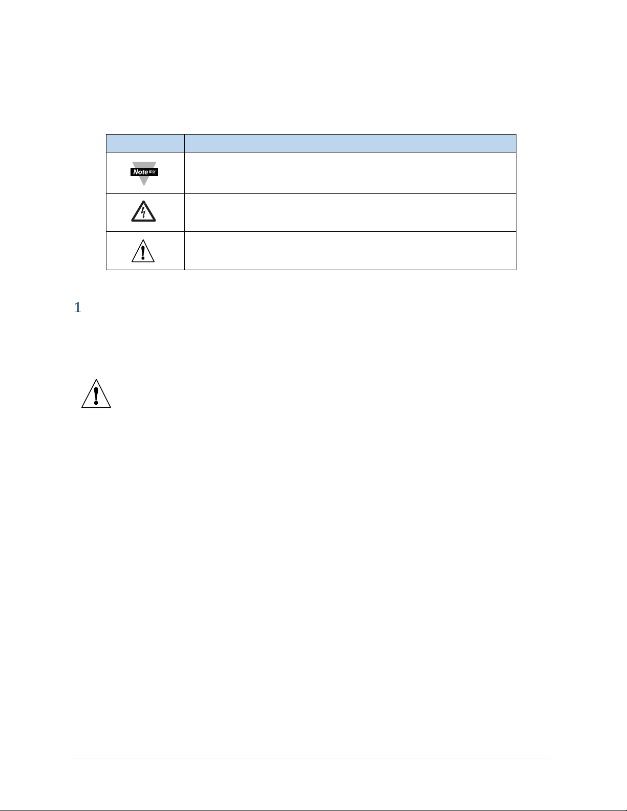
NOTES, CAUTIONS & WARNINGS
Symbol
Description
NOTE:
Information that is important to successfully setup and
use the zwSeries Wireless System.
CAUTION:
Risk of electrical shock.
WARNING:
May effect the functionality of the device.
Information that is especially important is identified by the following labels:
INTRODUCTION
1.1 Safety and EMC Considerations
ESD Warning
Warning:
The following parts of the unit are ESD sensitive:
•
The Antenna
•
Metal connectors for the Antenna, USB Port, and Power
EMC Considerations:
•
Whenever EMC is an issue, always use shielded cables.
•
Never run signal and power wires in the same conduit.
•
Use twisted-pair wires for differential signal connections.
•
Install Ferrite Bead(s) on signal wires close to the instrument if EMC problems persist.
•
Failure to follow all instructions and warnings may result in injury.
1.2 Environmental and Operating Conditions
The ZW-REC is designed to be fixed mounted and operated in a clean and dry environment.
Care should be taken to prevent the components of the device from being exposed to
moisture, toxic chemicals, extreme cold or hot temperature that are outside the specification
listed in this manual. Refer to
Operating Conditions.
The following is a list of basic good practices when operating this Wireless System.
•
Do not operate the wireless device in flammable or explosive environments.
•
Do not use the wireless device in medical, nuclear or any other critical application
where failure can cause damage or harm.
•
Always operate the device within the recommended environmental limits specified in
this manual.
•
Do not operate the device with a battery or AC adapter other than what’s supplied or
Section 7
for more information on allowable Environmental and
3 | P a g e
Page 6
specified in this manual or on the battery compartment label.
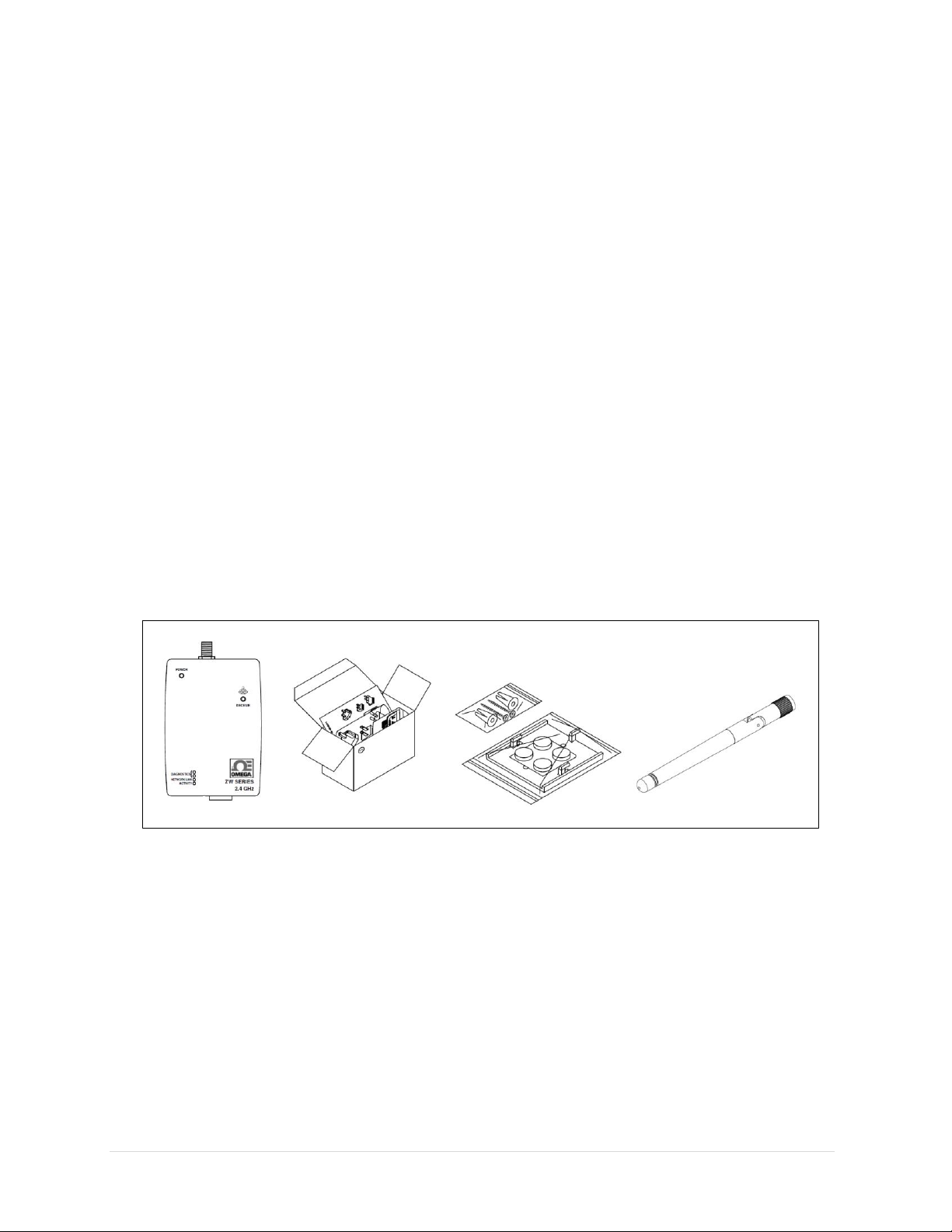
Figure 1. Included Items
•
Keep each wireless device at least 8 inches (20 cm) from other radio transmitters,
antennas, and people.
•
The wireless approvals for this device specifies the specific antenna supplied with this
device.
1.3 Before Begining
Inspecting the Shipment
Remove the packing slip and verify that you have received everything listed. Inspect the
container and equipment for signs of damage as soon as you receive the shipment. Note any
evidence of rough handling in transit. Immediately report any damage to the shipping agent.
The carrier will not honor damage claims unless all shipping material is saved for inspection.
After examining and removing the contents, save the packing material and carton in the event
reshipment is necessary.
If you need assistance, please contact the Customer Service Department nearest you.
Obtaining User Manuals and Software
A quick start guide is included with the ZW-REC. The latest user manual, firmware upgrades
and free software, such as Omega Dashboard, are available at the website listed on the cover
page of this manual.
1.4 Included with the ZW-REC
•
ZW-REC Wireless Receiver
•
Universal AC Adaptor with US, EU and GB prongs
•
Mounting Kit including screws, anchors, mounting bracket and feet.
•
2.4GHz Antenna
•
Quick Start Guide
4 | P a g e
Page 7

1.5 Description
The new, high-performance, long range, OMEGATM ZW-REC wireless receiver provides
Web-based monitoring of OMEGA’s IEEE 802.15.4 compliant wireless End Devices including
the zSeries, UW Series1 and zwSeries.
The ZW-REC is IEEE 802.15.4 compliant and operates at 2.4 GHz. It is designed to
communicate up to 1000m2 (3280') to various wireless sensors including the all new ZW-ED.
The ZW-REC connects directly to an Ethernet network to serve active web pages and display
the data. It enables monitoring and recording of Temperature, Humidity, and Barometric
Pressure over an Ethernet network or the Internet without any special software—just a Web
Browser. OMEGA offers a wide variety of different wireless sensors and transmitters to suit
every application.
The ZW-REC offers expanded functionality over previous wireless receivers. The ZW-REC can
connect to up to 1283 wireless End Devices at once. The built in web server supports
encryption to protect your sensitive data. The all new web pages run HTML5 and are ready to
use on mobile devices. The ZW-REC can also wirelessly update firmware for compatible End
Devices and Sensors.
The ZW-REC is designed to require no software to setup and run. A standard web browser can
be used to monitor and chart all sensor readings. The browser can also be used to configure
the device’s IP address, passwords for access and overall configuration parameters. Firmware
updates for the ZW-REC itself, compatible End Devices and sensors are loaded directly from
the web browser. The web server supports HTTP over TLS (HTTPS) which provides a secure,
encrypted, connection between web browser and ZW-REC receiver.
Each ZW-REC receiver can support up to 128 End Devices and up to 8 receivers can be setup in
one area allowing for networks of up to 1024 total End Devices. The Omega Dashboard web
server software can monitor and log data from one or more receivers from a single webpage.
The Omega OPC Server is available for customers with existing SCADA systems, to connect the
ZW-REC directly to their PLC or Historian. A free trial of the OPC Server is available for
evaluation purposes. Please contact Customer Service for more information.
1
Refer to the Omega Website for a list of compatible UW Series devices.
2
Without obstructions or interferences
3
Requires end devices that support IDs 32-127.
5 | P a g e
Page 8

HARDWARE
Item
Description
Item
Description
1
Antenna Connector
9
Mounting Bracket Holes
2
Power LED
10
Serial Number
3
USB Connector1
11
Network ID DIP Switches
4
Network / Diagnostic LEDs
12
Network ID Label
5
Power Connector
13
MAC Address Label
6
Reset Button
14
IP Address Label
7
Ethernet Connector
15
Configuration DIP Switches
8
Wireless Link LED
16
Analog / Alarm Output (Optional)
Figure 2. ZW-REC Parts Diagram
2.1 ZW-REC Diagram
TM
1
Factory Use Only
6 | P a g e
Page 9
2.2 DIP Switches
Switch
NID
PAN
ID
Switch
NID
PAN
ID
8 7 6 5 8 7 6
5
OFF
OFF
OFF
OFF
0
13106
ON
OFF
OFF
OFF
8
13114
OFF
OFF
OFF
ON 1 13107
ON
OFF
OFF
ON 9 13115
OFF
OFF
ON
OFF
2
13108
ON
OFF
ON
OFF
10
13116
OFF
OFF
ON
ON 3 13109
ON
OFF
ON
ON
11
13117
OFF
ON
OFF
OFF
4
13110
ON
ON
OFF
OFF
12
13118
OFF
ON
OFF
ON 5 13111
ON
ON
OFF
ON
13
13119
OFF
ON
ON
OFF
6
13112
ON
ON
ON
OFF
14
13120
OFF
ON
ON
ON 7 13113
ON
ON
ON
ON
15
13121
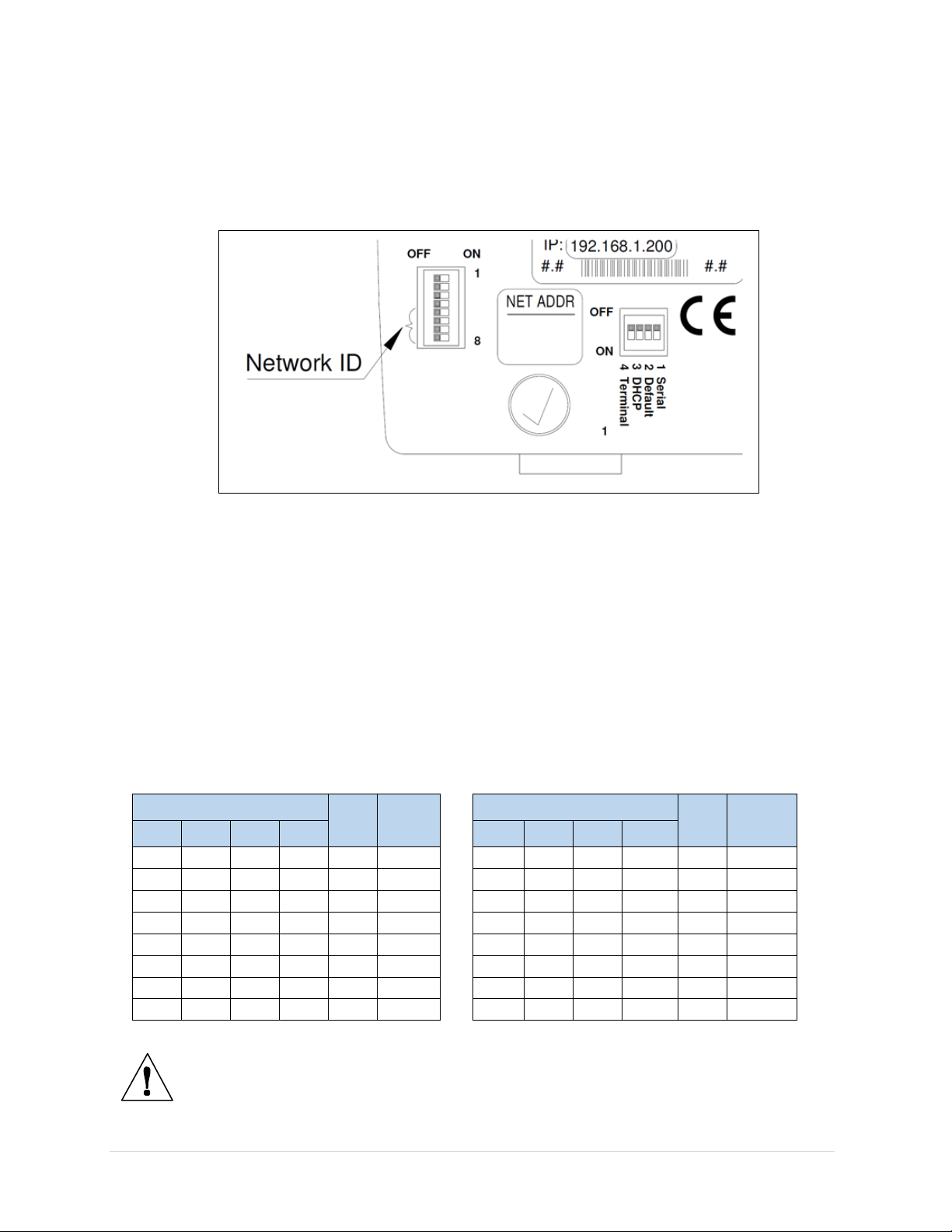
Figure 3. DIP Switch Detail
The ZW-REC has two banks of DIP switched located on the back of the unit for easy
configuration.
a tweezer or small screwdriver to gently push the switch. Do not apply excessive force.
Figure 3
shows a close up view of the switches. To change the DIP switches, use
Setting the Network ID
The set of 8 switches on the left selects the Network ID. The Network ID (NID) identifies which
End Devices the ZW-REC communicates with. If there are multiple Receivers deployed in the
same area each one must be assigned a unique NID. Make sure the same NID is selected on
the ZW-REC and the End Devices. Only switches 5 to 8 are used. Do not use switches 1 to 4.
zSeries End devices only support NIDs 0 to 7. UW Series End Devices require a 5 digit NID
referred to as a PAN ID for configuration. The PAN ID corresponding to each NID is listed in
Table 1
. Consult the user manual of each specific End Device for more information.
Table 1. Network ID DIP Switches
Warning:
type of End Device. Please refer to the user manual for the End Device to
determine which switches correspond to the NID.
The NID may be set with a different set of switches depending on the
7 | P a g e
Page 10
DHCP and Defaults
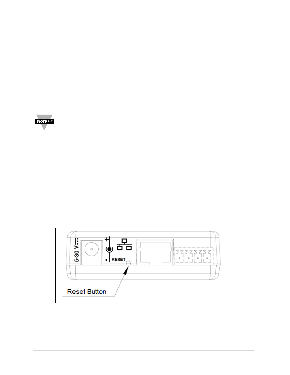
Figure 4. Reset Button
The set of 4 switches near the Ethernet port are for basic configuration. Switches 1 and 4 are
reserved and should not be used.
Switch 2 is used to reset the ZW-REC to factory defaults. This is useful if the IP address or
password to the ZW-REC is lost. To set the Receiver to factory default settings perform the
following steps:
•
Remove power from the ZW-REC.
•
Slide DIP switch #2 to ON position.
•
Power the ZW-REC on and wait about 10 seconds until the Receiver fully boots up.
•
Set the DIP switch #2 back to OFF position
Note:
Make sure that the DIP switch is set to OFF before resuming normal
operation. When the switch is on, every time the unit is power-cycled the factory
settings are loaded. The switch may be changed while the unit is running but this
has no effect until the ZW-REC is reset or power cycled.
Switch 3 is used to force DHCP on. Changing Switch 3 to ON enables DHCP the next time the
ZW-REC is powered or reset. Turning on DHCP in the manner overwrites the webpage setting.
This is useful for situations where it is not possible to connect to the default IP address. Please
see
Section 3.3
To disable forced DHCP change Switch 3 to OFF and reset the device. DHCP remains on until it
is changed from the webpage or the device is reset to defaults.
for more information on requirement to use DHCP.
2.3 Reset Button
Pushing the Reset Button while the ZW-REC is powered reboots the device. Holding the Reset
Button for 9 seconds resets the ZW-REC to its factory default settings. To access the Reset
Button carefully use a small screw driver or paperclip to depress the switch through the
pinhole shown in
Figure 4
. Do not apply excessive force as this may damage the device.
8 | P a g e
Page 11
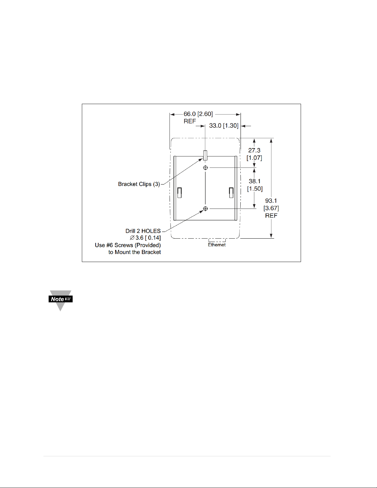
2.4 Dimensions and Mounting
Figure 5. Mounting Dimensions
The ZW-REC includes all required hardware for mounting. To mount the ZW-REC position unit
where required. Mark the location of the top center of the unit. Refer to
drill the two screw holes as indicated. Use the included drywall anchors if needed and mount
the bracket so that the bracket clips are facing up. Align the back of the unit over the three
clips. When engaged slide downward and snap the unit in place.
Figure 5
to mark and
•
When mounting the unit be sure to leave room on the top for the Antenna
and on the bottom and side for the cables.
•
Mount the unit away from any large metal obstructions such as posts,
catwalks or large machinery.
•
For best wireless range, do not co-locate the ZW-REC with other 2.4GHz
wireless equipment such as wireless routers or access points.
•
For best wireless range, elevate the ZW-REC and keep a direct line of sight
to End Devices.
9 | P a g e
Page 12

INITIAL SETUP
This section guides you through how to setup the ZW-REC. Please do not power on any End
Devices until Initial Setup is complete. If the ZW-REC is being integrated into a deployment
with existing End Devices those End Devices may need to be reset once the ZW-REC is
configured.
3.1 Antenna Warning
Before powering up the ZW-REC ensure the supplied antenna is properly installed. Running
the ZW-REC without an antenna, or with an unapproved antenna, may cause damage to the
device and/or cause operation outside of regulatory compliance. Omega Engineering accepts
no liability and issues no warranty for devices operated improperly.
3.2 Choosing a Network ID
The Network ID (NID) selects which End Devices the ZW-REC communicates with. The NID is
selected using the DIP switches found on the back of the device. If this ZW-REC is replacing an
existing receiver in a wireless sensor installation, determine which NID is currently used and
use the same one. Refer to
NID.
In a new installation with only one Receiver, keeping the default NID of 0 is recommended. All
End Devices ship with a default NID of 0. If this installation requires multiple Receivers, ensure
that each Receiver has a unique NID.
Record the NID on the Net. Addr. label on the back of the ZW-REC for easy reference in the
future.
Section 2.2
to determine the correct DIP switch settings for each
3.3 Connecting to the ZW-REC
Power on the ZW-REC at by plugging in the supplied AC adaptor. The Green Power LED lights
up and the Blue Receive LED flashes. The ZW-REC performs an energy scan to determine what
the best RF frequency to transmit on is. Once the energy scan has completed the Blue LED will
remain lit. See
Connect the ZW-REC to your network or computer using an Ethernet Cable. When connecting
the ZW-REC directly to a computer a crossover cable is needed if the network adapter is an
older 10Base-T or 100Base-TX type. A normal cable can be used for modern 1000Base-T
network adaptors. The green Network Link and Activity LEDs light up once a connection has
been established.
Section 5.4
for more information on the energy scan.
Static IP Address
The ZW-REC comes configured from the factory with a default IP address of 192.168.1.200.
This address appears on a label on the back of the device. Bring up the ZW-REC web page by
navigating to http://192.168.1.200 in your web browser.
DHCP/DNS
In installations where a static IP address is undesirable, an IP address can be automatically
assigned using a DHCP server. See
Section 5.2
for more information.
10 | P a g e
Page 13

3.4 Default Passwords
User Account
Login Name
Password
Client
login
12345678
Administrator
admin
00000000
Figure 6. End Device Readings (Blank)
A password is required to view the ZW-REC web page. Enter the Client information in the
dialog box when prompted. The default usernames and passwords are shown in
Table 2
.
Table 2. Default Passwords
The Client account is used to view reading and setup sensors. The Administrator account can
change network options, update firmware and enable or disable security features. The default
passwords can be changed from the Security page. It is recommended that you change these
passwords. See
Section 6.1
for more details.
3.5 Navigating the Webpage
The End Device Reading Page (
The page will initially have no entries. End Devices are automatically added to the page as
they are connected to the ZW-REC.
The End Device Readings Tab is highlighted in the Navigation Bar at the top of the page
indicating the current page. To navigate to a different page, click the corresponding tab in the
navigation bar. The End Device Status and Charting tabs bring up additional information about
connected End Devices. These three pages require the Client Account credentials and are
described in more detail in
The System tab and Security tab deal with ZW-REC wireless and Ethernet network
configuration, encryption, logins and other system details. These pages require Administrator
credentials and are described in more detail in
Figure 6
Section 4
) is shown by default when logging into the ZW-REC.
.
Section 5
and
Section 6
.
11 | P a g e
Page 14

END DEVICE READINGS AND CONFIGURATION
Figure 7. End Device Readings (Populated)
This section details how to view, log and chart data received from End Devices. Turn on and
configure any End Devices now. Confirm that all End Devices are set to the same Network ID
as the desired ZW-REC. Also ensure each End Device has a different Device ID selected. If an
End Device is running, it needs to be reset after changes to the Device ID or Network ID.
Power on all End Devices now. If existing End Devices are running they may need to be reset
now.
Please refer to the End Device user manual for detailed instructions on setting Network IDs
and Device IDs.
The ZW-REC can display a NID chart to help configure zSeries and zwSeries End
Devices. Refer to
4.1 End Device Readings Page
When logging into the ZW-REC the End Device Readings page is displayed. The readings page
shows the current sensor data from all connected End Devices. When an End Device turns on
it enters active scan mode and search for a receiver. When the ZW-REC is found the Blue
Wireless Link Indicator on the End Device flashes once and turns off. The Link Indicator flashes
again each time a reading is transmitted. Once an End Device finishes connecting to the ZWREC it is automatically added to the reading page.
Section 5.1
for more information.
The readings page shows the End Device ID, Name and Status followed by readings from any
connected sensors. End Device Status will change from Good to Lost if an End Device misses
three transmissions in a row.
The Sequence Number is transmitted by the End Device and incremented with each
transmission. An increasing sequence number shows that the web page is getting fresh data
12 | P a g e
Page 15

from the End Device. The Sequence Number resets to 0 after it reaches 255.
Figure 8. End Device Settings
The Last Update field shows the last time a new measurement was updated on the webpage.
The webpage update rate is set at the bottom of the page. This changes how often the
webpage checks for readings but does not change how often End Devices transmit new
readings. The Last Update field uses the time retrieved from the local system.
By default, End Devices are displayed sorted by Device ID and up to 10 End Devices are
shown. Use the
number of entries can be changed using the drop down menu in the upper left. Up to 100 End
Devices can be displayed at once.
When dealing with a large number of End Devices it may be useful to filter which ones to
view. Use the search bar in the upper right to search for specific end devices by name. Use the
Device Filter
Previous
button to show or hide specific End Devices by Device ID.
and
Next
buttons to show additional End Devices. The maximum
4.2 Changing End Device Settings
Connected End Devices and Sensors can be configured by clicking the settings icon on the
right side of the page, on either the Readings or Status Page. A list of user adjustable
parameters including the Sensor Name, Update Interval, and Sensor Offsets are shown. Other
parameters may be shown based on the connected sensor. Please refer to the Sensor User
Manual for sensor specific instructions.
General Settings
The End Device Name can be up to 16 characters long.
Names are displayed on the web pages with the Device
ID to help differentiate between End Devices.
The name cannot contain any of the following
characters: ; = ( ) < > “ &
The Update Interval is the frequency End Devices
transmit readings. By default, most End Devices send one
reading every 10 seconds. The update interval greatly
effects the battery life of End Devices. The shorter the
update interval the shorter the battery life will be.
Shorter update intervals also increase the chance of RF
Interference when there are multiple End Devices. It is
recommended that the update interval be set only as
short as required for optimal battery life. Please refer to
the End Device user manual for more information on
battery life.
Each End Device can have multiple sensors. The Sensor
Offset is used to make adjustments to each
measurement as needed. The offset can be positive or
negative and contain up to 4 decimal places. The End Device will round each reading to the
local sensor accuracy so extra decimal places may not be reflected in the final reading. If the
End Device has a display, the offset will also be reflected on the display.
To change a value in the General section, type the desired value into the dialog box and press
the
Update
Fields
button. Changes are sent to the End Device after its next transmission. The
button clears any changes made but not yet updated.
Reset
13 | P a g e
Page 16

Special Functions
In a large deployment it may be difficult to know which End Device is currently being
configured. Checking the
End Device being configured. Once the End Device has been located uncheck
setting to turn off the LED. Leaving the LED on will quickly drain the battery on battery
powered units and new readings may not be taken by certain devices in identify mode.
The
Clear End Device
remove any Lost devices from the webpage and clear any errors. If the
button is pressed when there are no error conditions, the End Device will be removed but
immediately rejoin the network when it next transmits.
The
Reset End Device2 button resets the End Device if it is currently connected to the
network. The End Device will reset itself the next time it sends a reading to the ZW-REC and
re-join the network automatically.
Identify Mode1 setting turns on the Blue Wireless Link LED on the
Identify Mode
button removes the End Device from the ZW-REC data base. This will
Clear End Device
1
Identify Mode not available for UW Series End Devices
2
Reset End Device not available for UW Series End Devices
14 | P a g e
Page 17

4.3 End Device Status
Name
Description
Type
Model of End Device
Sensors
Number of Sensors Connected
Power
Current Power Source (Battery or Line Power)
Success
Percent of successful transmissions
Strength
Update Interval
Time Between Readings
Battery
Current Battery Voltage of End Device
Figure 9. End Device Status Page
The End Device Status
status. The page functions similarly to the End Device Readings page. Use the Previous and Next
buttons to navigate between pages of End Devices. End Devices can be selected and filtered in the
same way as the reading page.
page provides a quick overview of all current connected End Devices and their
Wireless Signal Strength (See
APPENDIX C)
15 | P a g e
Page 18

4.4 Chart Page
Item
Name
Description
1
Toolbar
Chart Utilities
2
Key
Displayed Sensors
3
Axis 1
Axis for Measurement Type 1
4
Axis 2
Axis for Measurement Type 2
5
Time Span
Length of Time Charted
6
Update Time
Time Between Updates
1
2
3
4
5 6
Figure 10. Chart Page
The Chart page gives a graphical view of the sensor data.
Figure 10
shows the chart interface.
The Chart is highly customizable based on your needs. Any combination of End Devices can be
charted and two measurement types can be displayed at once.
16 | P a g e
Page 19

Setting up the Chart
Item
Name
1
Select End Devices
2
Select Sensor Types
3
Save Graph Data
4
Reset Zoom
21 3 4
Figure 11. Chart Toolbar
Figure 12. Chart Axis Dialog
The first time the chart is loaded it is blank. To start graphing, first use the toolbar in the
upper left of the chart to select which end devices to view. Next select which sensor type to
view. The chart will now start to display the data. Up to two different sensor types can be
selected. The first is plotted on the left axis and the second is plotted on the right axis.
As End Devices are added to the chart they also appear in the key above the chart. Each
measurement in the chart is displayed in a different color. The key displays the color followed
by the End Device ID, the sensor number and the units of measure for each measurement.
The sensor number is used to distinguish between sensors for units equipped with more than
one sensor of the same type such as dual thermocouple inputs.
Manipulating The Chart
All chart axes are fully user customizable. By
default, the cart will show one hour of data
and scale each axis to fit the sensor
readings received. The scale on each axis
can be fixed to user defined extents and the
amount of time shown can also be
customized.
To change the scale of a vertical axis, click
on the axis title, enter the desired
Maximum and Minimum for the axis and
press the
Use the
scale to fit the data.
To change the horizontal axis, enter the desired chart time, in minutes, into the time span box
at the bottom of the chart. This indicated how much time the chart will cover. The chart
always displays the most recent data. The frequency the chart is updated can also be
changed. Enter the desired frequency in the update time box.
Set
button to change the scale.
Auto Scale
Note:
Devices. If the chart updates more often than the End Device, it will display the
same data point multiple times.
button to have the chart
The update time for the chart is unrelated to the update time for End
17 | P a g e
Page 20

Viewing Chart Data
Figure 13. System Information
The Chart has several helpful feature to make viewing data easier. Move the mouse over any
data point to show the sensor reading for that data point. Click and drag on the chart to zoom
into a specific section. Click the
Graph Data
value (csv) file which is readable by most programs.
button will save all of the points displayed on the graph to a comma separated
Note:
Data is lost after closing the chart page. Data older than the time span is lost
and will not be displayed on the chart. For long term data logging please use the
Omega Dashboard Software.
Reset Zoom
button to zoom out to the full extents. The
Save
System Page
The ZW-REC System page is used to setup the Radio and Network parameters for the device
and to upgrade firmware. The administrator login is required for this page. Changes to these
settings could cause loss of connectivity to the webpages or the connected End Devices. Care
is advised when making any changes. Some settings on this page require a reboot to take
effect. The ZW-REC can be rebooted using the
the page.
Note:
For detailed instructions on upgrading firmware see
Reboot ZW Receiver
button at the bottom on
APPENDIX B
.
5.1 System Information
System information is displayed at the top of the
page. The current version on Baseboard and radio
firmware is listed as well as the PAN ID. The PAN ID
is similar to the Network ID and is used for setting
up UW Series End Devices.
Clicking on the information icon next to the PAN ID
brings up a DIP Switch configuration chart for
zSeries and zwSeries End Devices. This chart shows
which DIP switches need to be used to connect the
End Devices to the ZW-REC. Refer to the End Device
User Manual for more information on End Device
setup.
18 | P a g e
Page 21

5.2 Network Setup
Figure 14. Network Configuration
The Network options configure the webserver in the ZW-REC. A reboot of the ZW-REC is required after
changing any network settings. The ZW-REC can be rebooted by using the Reboot ZW Receiver button
at the bottom of the page.
IP Address
To change the default static IP settings, enter the new information into the dialog boxes. Press
the
Save
button to confirm any changes. Changes will take effect the next time the ZW-REC is
rebooted.
•
When changing the ZW-REC to an IP address on a different subnet you will
be unable to access the webpage until you connect your computer to that
that subnet.
•
If you change the IP address it is highly advised that the label be updated.
Remove the IP Address sticker and write in your new IP address in the area
provided.
Host Name, DHPS and DNS Server
The default host name for the ZW-REC is zwrec**** where **** are the last 4 digits of the
MAC Address. See
The ZW-REC can be accessed using its host name instead of its IP address. To use this feature
DHCP must be with a Domain Name Server (DNS).
Enabling DHCP on the ZW-REC allows a DHCP Server to automatically assign an IP address.
Checking the DHCP box overwrites the static IP settings. Be sure to also enter the address of
the associated Domain Name System (DNS) server when DHCP is enabled. A DNS Server links
the device’s host name to its IP address. If DHCP is turned on but a DNS server is not available,
it may be difficult to locate the correct IP address to connect to the ZW-REC.
After changes are made, press the
effect the next time the ZW-REC is rebooted. Please note that it may take a few moments for
Figure 2
for the location of the MAC address.
Save
button to save the new settings. The changes will take
19 | P a g e
Page 22

the DNS server to recognize the receiver after a reboot.
Name
Description
Maximum Client
Connections
The number of open connections allowed. Additional
connections over the limit are refused.
The ZW-REC supports up to 5 client connections but the
number of connections is limited to 2 when encryption is
enabled.
Client Connection Port
The port number for external software to connect to.
Disconnect After Data Sent
The ZW-REC will close the port after each command. This is
useful if multiple programs require access simultaneously.
Require Authentication
Prompts for Client Password before establishing a
connection.
Figure 15. Client Connection Configuration
•
It is important to communicate with the network administrator, in order to
understand DHCP and its existing configurations on the host server, before
enabling DHCP on the Receiver.
•
On Windows servers DHCP and DNS are separate functions. It is important
to configure the DHCP server to communicate with the DNS server in order
for the Host Name to be correctly identified.
•
If the ZW-REC cannot be reached using its Host Name, please contact your
network administrator to make sure the DHCP server and DNS are properly
configured.
5.3 Client Connection
The Client Connection options configure how TCP connections are handled. Client connections allow
external software to read data from the ZW-REC using the ZW-REC Serial Protocol detailed in the ZWREC Serial Programming Guide. The default options work with the Omega Dashboard. If different
software is used these setting may need to be changed. Press Save to save any changes. The changes
will take effect the next time the ZW-REC is rebooted.
20 | P a g e
Page 23

5.4 Radio
Figure 16. Radio Configuration
When the ZW-REC starts up it performs an energy scan to find a clear RF channel. This RF channel is
displayed in the Radio Section. Due to network planning this channel may need to be changed. Select
the desired channel here. If the RF Channel is changed all connected End Devices need to be reset. To
prevent the ZW-REC from re-scanning when it is rebooted uncheck the Enable Energy Scan box. Press
the Save button to save any changes. Changes in this section take place immediately.
Note: It is highly recommended to uncheck the Enable Energy Scan Box after the first boot
up. This allows End Devices to automatically re-connect to the ZW-REC if it is rebooted. If
left checked, End Devices may need to be reset when the ZW-REC is rebooted.
5.5
Measurement Units
This section selects between SI and Imperial units for temperature and pressure. Changes in
this section take place immediately. End Devices with LCDs will reflect the new setting after
they next transmit.
Note: End Devices with LCDs always display local readings in SI units.
Figure 17. Measurement Units
21 | P a g e
Page 24

Security Page
User Level
Password
Client
Omeg15c!
Administrator
Omeg15a!
Figure 18. Authentication
Figure 19. Change Password Dialog
The Security Page controls logins and
encryption for the ZW-REC. The ZW-REC
ships with encryption off and easy to
remember passwords by default. For secure
applications Encryption and Strong Password
enforcement are available. After making
changes on the Security page reboot the ZWREC using the
the bottom of the page.
6.1 Usernames and Passwords
To change the default user name for the
Client or Admin account, type the desired
name in the dialog box. Click on the
button to confirm any changes.
The change a password, click the button
next to the username. In the dialog box,
enter the old password followed by the new
password. Retype the new password for
confirmation. Click the
submit changes.
By default, any password up to 16 characters
long is allowed by the ZW-REC. If additional security is required check the require Strong
Password box to enable the Strong Password Policy.
Reboot ZW Receiver
Submit
button to
button at
Save
Strong Password Requirements
•
Length of at least 8 characters but no more than 16 characters
•
At least 1 uppercase letter (A-Z)
•
At least 1 lowercase letter (a-z)
•
At least 1 numerical digit (0-9)
•
At least 1 special character (any other character not including ;=()[]<>"&)
The password requirements can be viewed by clicking the information icon. If the current
passwords do not meet the password policy, they are automatically reset to the defaults
shown in
Table 3
. Usernames remain the same.
Table 3. Default Strong Passwords
Reboot the ZW-REC after completing changes to the usernames or passwords. The new credentials are
enforced following the reboot.
22 | P a g e
Page 25

6.2 Encryption
Figure 20. Certificate Warning
Check the Use Encryption box on the Security page to turn on encryption for the webpage and
client connections. A reboot is required after enabling encryption. After encryption is enabled,
login to the ZW-REC using https:// followed by the ZW-REC IP address or hostname.
When encryption is enabled the ZW-REC is configured with a default SSL certificate that is not
issued by a Certificate Authority (CA). Most web browsers provide a warning page when
connecting to the ZW-REC indicating the SSL certificate is not issues by a trusted certificate
authority. This is normal and it is safe to procced. Click ‘
the ZW-REC Home Page. A sample warning displayed by Internet Explorer is shown below in
Figure 20
.
Continue to this website
’ to bring up
This warning can be eliminated by obtaining a trusted SSL certificate. For details on how to
use a trusted SSL certificate please refer to
APPENDIX A
.
23 | P a g e
Page 26

SPECIFICATIONS
Wireless Communications
Standard
IEEE 802.15.4, DSSS
Frequency
2.4GHz
Transmit Power
9.5dBm
Receiver Sensitivity
-96dBm
Range
Up to 1000m (3280’)
Compatible Transmitters
zwSeries
Up to 128 Devices
zSeries
Up to 32 Devices
UWTC, UWRTD, UWRH, UWIR
Up to 48 Devices
Operating Conditions
Input Voltage
5VDC to 30VDC
Input Power
0.8W Maximum
Operating Temperature
0 to 70°C (32 to 158°F)
Humidity
90% RH non-condensing
Physical Properties
Case Dimensions (W x H x D)
66 x 93.1 x 27.4mm (Excluding Antenna)
Antenna Length
108mm
Weight
90g (Including Antenna)
Networking and Security
Ethernet
10/100Base-T
IP Address
Static or DHCP Assigned
Encryption
TLS 1.2 with AES_256_CBC
User Accounts
Client and Administrator
Safety Qualified AC Adaptor
Input Voltage
100VAC to 240VAC, 50/60 Hz
Nominal Output
9 VDC, @ 0.5A
Operating Temperature
0 to 40°C (32 to 104°F)
Export Control Classification Number
ECCN
5A992
24 | P a g e
Page 27

Approval Information
The product herewith complies with the essential requirements and other relevant
provisions of the directives listed below and carries the CE-marking accordingly.
The following CE Mark is affixed to this equipment.
The CE declaration is available at the website listed on the cover page of this manual.
EMC Directive
2014/30/EU
Low Voltage Directive
2014/35/EU
Radio Equipment Directive
2014/53/EU
RoHS Directive
2011/65/EU
25 | P a g e
Page 28

APPENDIX A Certificate Configuration
Figure 21. Certificate Configuration
The ZW-REC is configured with a default SSL
certificate not issued by a Certificate Authority
(CA). The non-verified certificate causes most
web browsers to display warning messages. A
CA-issued SSL certificate can be used instead
and will not trigger warnings. This may make
for a better user experience.
Omega cannot provide a CA signed certificate
because a private encryption key is required
to be stored on the device. Distributing a
private encryption key compromises its
security. Always protect your encryption key.
A stolen encryption key can be used to spoof
your presence on the internet. Omega is not
responsible for and does not have any
obligation towards the process of obtaining a
certificate or protecting your encryption key.
Create Certificate Validation Page
Some Certificate Authorities require a verification page to ensure that the website is
authentic. The ZW-REC can automatically generate the required verification page. The
certificate issuer is allowed to remotely access to this page to verify the website.
To create a validation page, enter the name of the validation page to be created in the Page
Name box and enter the information provided by the CA in the page content box. Click the
Create
this process.
button to finalize the process. Please contact your CA if you have any questions about
Upload a Certificate
Once you have obtained a certificate, you can upload it to ZW-REC. The certificate contains
two parts; the Certificate and the Private Key. Click on the
Certificate and Private Key fields shown in
corresponding file. Make sure the correct files are selected before uploading the certificate.
Click the
Upload
button to upload the certificate and finish the process.
Figure 21
. Use the file browser to find the
Choose File
button next to the
Reset the Certificate
To remove the CA issued certificate and use default certificate click the
button.
Reset Certificate
26 | P a g e
Page 29

APPENDIX B Firmware Updates
Figure 22. Old Firmware Upgrade Page
The ZW-REC firmware and zwSeries End Device Firmware can be updated through the
network connection. A firmware update may add additional features or allow the ZW-REC to
communicate with additional End Device models. To update the firmware first visit the ZWREC page at www.omega.com. Download the latest firmware version and unzip the file to a
location a local drive.
Before starting a firmware upgrade, close all unused programs, unused web browser tabs and
disable anti-virus software if possible. It is recommended that any firmware upgrade is
initiated on the same local area network as the ZW-REC using a wired Ethernet connection.
This will reduce the risk of dropped packets or network traffic interfering with the upgrade.
B.1 Upgrading from Version 1.X
ZW-REC units running version 1.X firmware require a multi-part update to run version 2.0 or
above. Download the Version 1.X upgrade files from the Omega website and unzip the files to
a local directory. Confirm that the following files are included:
•
ZW_COORD_BL.b64
•
coordinator.b64
•
zw-rec-app.b64
Step 1:
Step 2:
and log into the Access Control page
using the administrator log on.
At the bottom of the page press the
Firmware Upgrade
The Firmware Upgrade page
appears as shown in
the
will appear reminding you to have
your firmware ready. Click
Before proceeding, record the IP Address for the ZW-REC:
•
IP Address: http://__ __ __ . __ __ __ . __ __ __ . __ __ __
Connect to the ZW-REC
button.
Upgrade
Figure 22
button. A dialog box
Okay
. Click
.
27 | P a g e
Page 30

Step 3:
Figure 23. Old Firmware Upload Page
Figure 24. Old Upload Success Page
If the page does not come up
automatically after 10 seconds,
navigate to the IP address of the
ZW-REC. In firmware update mode
encryption is disabled so the IP
address needs to start with http://.
The ZW-REC will restart in firmware update mode as shown in
Figure 23
.
Step 4:
Locate the
using the dialog box. Press
selecting the file press the
to begin the firmware update. The
firmware update process may take
several minutes. Do not close the web
page or remove power from the device
until the update is complete. When the
update has finished the Update Success
screen in
Step 5:
instruction in Section B.2 Step 3 to upload
Step 6:
instruction in Section B.2 Step 3 to upload
The ZW-REC is now ready to use. User settings including, IP Address, Encryption, User Name
and Password are preserved during the update so no additional setup is required.
Press the
ZW_COORD_BL.b64
Figure 24
Connect to the ZW-REC again using the IP Address recorded in Step 1. Follow the
Connect to the ZW-REC again using the IP Address recorded in Step 1. Follow the
Browse
is shown.
button and
file
Open
. After
Send
button
coordinator.b64
zw-rec-app.b64
.
.
B.2 Upgrading Version 2.0 and above
Step 1:
Before proceeding, record the IP Address for the ZW-REC:
•
IP Address: http://__ __ __ . __ __ __ . __ __ __ . __ __ __
28 | P a g e
Page 31

Step 2:
Figure 25. Firmware Upgrade Dialog
Figure 26. Firmware Upload Page
Figure 27. Upload Success Page
the System page using the administrator log
on. At the bottom of the page press the
Update Firmware
bottom of the page.
A dialog box will pop up. Click OK and the
firmware update page will load. If the page
does not come up automatically after 10
seconds, navigate to the IP address of the
ZW-REC. In firmware update mode
encryption is disabled so the IP address
needs to start with http://.
Connect to the ZW-REC and log into
button located near the
Step 3:
Upgrade
Wait for the update success screen shown in
Press the
button to update the firmware.
Browse
button and select the firmware (b64 file) for the update. Press the
Figure 27.
Once the firmware is loaded the ZW-REC restarts and is ready to use. User settings including,
IP Address, Encryption, User Name and Password are preserved during the update so no
additional setup is required.
29 | P a g e
Page 32

B.3
Figure 28. End Device Update Page
Updating zwSeries End Devices
The ZW-REC can upgrade the firmware of zwSeries End Devices. To initiate an update,
navigate to the System Page and click on the
Update Dialog in shown in
firmware version and model type displayed.
Figure 28.
Update End Devices
All compatible End Devices are listed with their name,
button. The End Device
Step 1:
Step 2:
search for specific End Devices or select all end devices on the page using the
button on the bottom of the page.
Step 3:
the ZW-REC. The ZW-REC will then update each selected End Device the next time it checks in.
The update process may take several minutes for each End Device and the ZW-REC will finish
updating one End Device before starting on the next. While the upgrade is happening the End
Device being upgraded will not record data or transmit readings. All other End Devices will
function normally and the ZW-REC will continue to function normally.
Once an End Device is updated it reboots and reconnects to the ZW-REC. The new Firmware
number is shown in the End Device Status Page.
Click on the
Select the end devices to update from the list. If needed, use the search dialog box to
The
Upload File
Note:
End Device Being Upgraded my need to be restarted before it will work again.
Choose File
button will now be usable. Click the button to upload the firmware to
If the ZW-REC or End Device is powered off during a Firmware Upgrade the
button and select the firmware update.
Select All
30 | P a g e
Page 33

APPENDIX C RF Topics
Figure 29. 2.4GHz Spectrum Map
This section discusses some topics to ensure the best RF coverage range.
C.1 RF Channel Selection
The 802.15.4 wireless standard uses 16 RF channels numbered 11 through 26. Each channel
has a bandwidth of 2MHz and channels are separated by 5MHz. When the ZW-REC is powered
on it automatically searches for the quietest channel to use for communications. You may also
choose to manually select your RF Channel. (See
Manually selecting an RF channel may be necessary if there are running multiple receivers in
one area. While multiple Receivers can coexist on the same RF channel, selecting different
channels is recommended. Using separate RF channels will reduce potential interference
between systems. This is particularly true for large deployments.
Wi-Fi networks may also create interference with the ZW-REC. Wi-Fi networks operate on
fixed frequencies with channels occupying 20MHz or 40MHz of bandwidth. While there are
many Wi-Fi Channels there are only a few non-overlapping channels that are generally used.
Figure 29
commonly used Wi-Fi Channels in North America and Europe. If the Wi-Fi channels currently
in use are known, select an 802.15.4 channel that does not overlap with it to reduce
interference.
shows the 802.15.4 channels mapped against the occupied bandwidth of the most
Section 5.4
)
C.2 Signal Strength Indicator
Signal Strength is displayed as a percentage, for each end device, in the End Device Status
Page. This indicates how well each End Device can hear the ZW-REC. The ZW-REC and most
end devices have a receive sensitivity of -96dBm or better. In most cases this means that a
Signal Strength reading of 15% to 20% is reasonable for maintaining reliable communication.
The ZW-REC transmits at a power of +9.5dBm. Certain End Devices are lower power than the
ZW-REC so the received signal strength is higher at the End Device than it is at the ZW-REC.
For these End Devices the Signal Strength indicator needs to be higher for reliable
communications. For these low power devices, a signal strength of at least 25% to 30% is
recommended.
Figure 30
measured in dBm which is a logarithmic term. For every 10dBm increase in receive power the
actual power is increased by 10 times. For Low Power End Devices, the received power at the
ZW-REC may be 10dBm, or more, lower than indicated by the Signal Strength field. Take this
into account when evaluating link quality for low powered devices.
shows the rough mapping from Received Power to Signal Strength. Receive power is
31 | P a g e
Page 34

0
10
20
30
40
50
60
70
80
90
100
-110 -100 -90 -80 -70 -60 -50 -40 -30 -20 -10
Signal Strength [%]
Power [dBm]
Signal Strength vs Recieved Power
Figure 30. Received Power Chart
C.3 Maximizing Range
Under favorable conditions the ZW-REC can achieve a line of sight wireless link distance of up
to 1000m. Generally, most indoor applications will not be able to achieve these distances
although steps can be taken to maximize range. Ensure the Receiver and End Device are
located away from large obstacles and other RF sources such as Wireless Access points and
microwave. Keep objects clear of the zone between the End Device and Receiver. Metal
objects, walls, and cubical partitions in particular will all significantly reduce the signal
strength.
The antenna provided with the ZW-REC is a dipole. Care must be taken in the positioning of
the antenna to achieve the best possible range. The gain of the antenna is lower along the
axis of the antenna. Do not point the ZW-REC Antenna in the direction of an End Device.
When possible, The ZW-REC antenna should be parallel to the End Device antenna. If the End
Device does not have an external antenna the longest dimension of the End Device itself
should be parallel to the antenna of the ZW-REC.
Keep the antenna away from dense or metallic structures. Metallic structures should be kept
away by at least 0.8" (2 cm), although 2.4" (6 cm) is recommended. Objects too close to the
antenna may screen the ZW-REC from End Devices. Reflections off of nearby objects can also
cause destructive interference reducing received signal strength.
For long distance connections the Receiver and the End Device should be elevated to keep the
signal from being attenuated by the ground. Elevate each device by at least 0.6 meters above
the ground for each 100 meters or separation. It is best to keep this same clearance distance
to walls, ceilings and other obstructions as well.
32 | P a g e
Page 35

APPENDIX D Wireless Certifications
D.1 Federal Communication Commission Interference Statement
Part 15C, Class DTS Intentional radiator
Contains TX FCC ID: TYOJN5168M5
Caution:
antennas should be located at a minimum 7.9" (200mm) or more from the body of
all persons.
This device complies with Part 15 of the FCC Rules. Operation is subject to the following two
conditions: (1) This device may not cause harmful interference, and (2) this device must
accept any interference received, including interference that may cause undesired operation.
This equipment has been tested and found to comply with the limits of a Class B digital
device, pursuant to Part 15 of the FCC Rules. These limits are designed to provide reasonable
protection against harmful interference when the equipment is operated in a residential
environment. This equipment generates, uses, and radiates radio frequency energy, and if not
installed and used in accordance with the instructions, may cause harmful interference.
However, there is no guarantee that interference will not occur. If this equipment does cause
interference to radio or television reception, which can be determined by turning the
equipment off and on, the user is encouraged to correct the interference by one of the
following measures:
•
Reorient or relocate the receiving antenna.
•
Increase separation between the equipment and receiver.
•
Connect the equipment to an outlet on a circuit different from which the receiver is
connected.
•
Consult dealer or an experienced radio/TV technician.
In order to comply with FCC radio frequencies (RF) exposure limits, dipole
FCC Radiation Exposure Statement:
This portable equipment with its antenna complies with FCC’s RF radiation exposure limits set
forth for an uncontrolled environment. To maintain compliance, follow the instructions
below;
1. This transmitter must not be co-located or operating in conjunction with any other antenna
or transmitter.
2. Avoid direct contact to the antenna, or keep it to a minimum while using this equipment.
33 | P a g e
Page 36

D.1 Industry Canada Statement
This device complies with Industry Canada
license-exempt RSS standard(s). Operation is
subject to the following two conditions: (1) this
device may not cause interference, and (2) this
device must accept any interference, including
interference that may cause undesired operation
of the device.
Le présent appareil est conforme aux CNR
d'Industrie Canada applicables aux appareils radio
exempts de licence. L'exploitation est autorisée aux
deux conditions suivantes : (1) l'appareil ne doit
pas produire de brouillage, et (2) l'utilisateur de
l'appareil doit accepter tout brouillage
radioélectrique subi, même si le brouillage est
susceptible d'en compromettre le fonctionnement
Contains Industry Canada ID IC: 7438A-CYO5168M5
This device has been designed to operate with antennas having a maximum gain of 2.2 dBi.
Antennas having a gain greater than 2.2 dBi are strictly prohibited for use with this device.
The required antenna impedance is 50 ohms.
Singapore
D.2 CE Statement
The following alert sign indicates that there are restrictions on usage of the
equipment in regards to power limitations on Equivalent Isotropic Radiated
Power (EIRP) levels in the European Community.
The Following Are User Restrictions:
•
Combinations of power levels and antennas resulting in a radiated power level above
10 mW - EIRP for Direct Sequence Spectrum (DSSS) devices are considered as not
compliant, and are not allowed for use within the European Community and other
countries that have adopted the European R&TTE directive 2014/53/EU or the CEPT
recommendation ERC/REC 70-03 or both.
•
This device has been designed to operate with antennas having a maximum gain of 2.2
dBi. Antennas having a gain greater than 2.2 dBi are strictly prohibited for use with this
device. The required antenna impedance is 50 ohms.
34 | P a g e
Page 37

WARRANTY/DISCLAIMER
OMEGA ENGINEERING, INC. warrants this unit to be free of defects in materials and workmanship for a
period of 25 months from date of purchase. OMEGA’s WARRANTY adds an additional one (1) month grace
period to the normal two (2) year product warranty to cover handling and shipping time. This ensures
that OMEGA’s customers receive maximum coverage on each product.
If the unit malfunctions, it must be returned to the factory for evaluation. OMEGA’s Customer Service
Department will issue an Authorized Return (AR) number immediately upon phone or written request.
Upon examination by OMEGA, if the unit is found to be defective, it will be repaired or replaced at no
charge. OMEGA’s WARRANTY does not apply to defects resulting from any action of the purchaser,
including but not limited to mishandling, improper interfacing, operation outside of design limits,
improper repair, or unauthorized modification. This WARRANTY is VOID if the unit shows evidence of
having been tampered with or shows evidence of having been damaged as a result of excessive corrosion;
or current, heat, moisture or vibration; improper specification; misapplication; misuse or other operating
conditions outside of OMEGA’s control. Components in which wear is not warranted, include but are not
limited to contact points, fuses, and triacs.
OMEGA is pleased to offer suggestions on the use of its various products. However,
OMEGA neither assumes responsibility for any omissions or errors nor assumes liability for
any damages that result from the use of its products in accordance with information provided
by OMEGA, either verbal or written. OMEGA warrants only that the parts manufactured by the
company will be as specified and free of defects. OMEGA MAKES NO OTHER WARRANTIES OR
REPRESENTATIONS OF ANY KIND WHATSOEVER, EXPRESSED OR IMPLIED, EXCEPT THAT OF
TITLE, AND ALL IMPLIED WARRANTIES INCLUDING ANY WARRANTY OF MERCHANTABILITY
AND FITNESS FOR A PARTICULAR PURPOSE ARE HEREBY DISCLAIMED. LIMITATION OF
LIABILITY: The remedies of purchaser set forth herein are exclusive, and the total liability of
OMEGA with respect to this order, whether based on contract, warranty, negligence,
indemnification, strict liability or otherwise, shall not exceed the purchase price of the
component upon which liability is based. In no event shall OMEGA be liable for
consequential, incidental or special damages.
CONDITIONS: Equipment sold by OMEGA is not intended to be used, nor shall it be used: (1) as a “Basic
Component” under 10 CFR 21 (NRC), used in or with any nuclear installation or activity; or (2) in medical
applications or used on humans. Should any Product(s) be used in or with any nuclear installation or
activity, medical application, used on humans, or misused in any way, OMEGA assumes no responsibility
as set forth in our basic WARRANTY/DISCLAIMER language, and, additionally, purchaser will indemnify
OMEGA and hold OMEGA harmless from any liability or damage whatsoever arising out of the use of the
Product(s) in such a manner.
RETURN REQUESTS/INQUIRIES
Direct all warranty and repair requests/inquiries to the OMEGA Customer Service Department. BEFORE
RETURNING ANY PRODUCT(S) TO OMEGA, PURCHASER MUST OBTAIN AN AUTHORIZED RETURN (AR)
NUMBER FROM OMEGA’S CUSTOMER SERVICE DEPARTMENT (IN ORDER TO AVOID PROCESSING
DELAYS). The assigned AR number should then be marked on the outside of the return package and on any
correspondence.
The purchaser is responsible for shipping charges, freight, insurance and proper packaging to prevent
breakage in transit.
FOR WARRANTY RETURNS, please have the
following information available BEFORE contacting
OMEGA:
1. Purchase Order number under which the product
was PURCHASED,
2. Model and serial number of the product under
warranty, and
3. Repair instructions and/or specific problems
relative to the product.
OMEGA’s policy
customers the latest in technology and engineering.
OMEGA is a trademark of OMEGA ENGINEERING, INC.
© Copyright 2018 OMEGA ENGINEERING, INC. All rights reserved. This document may not be copied, photocopied,
reproduced, translated, or reduced to any electronic medium or machine-readable form, in whole or in part, without the prior
written consent of OMEGA ENGINEERING, INC.
is to make running changes, not model changes, whenever an improvement is possible. This affords our
FOR NON-WARRANTY REPAIRS, consult
OMEGA for current repair charges. Have
the following information available BEFORE
contacting OMEGA:
1. Purchase Order number to cover the COST
of the repair,
2. Model and serial number of the product, and
3. Repair instructions and/or specific problems
relative to the product.
Page 38

Where Do I Find Everything I Need for
Process Measurement and Control?
OMEGA…Of Course!
Shop online at omega.com
TEMPERATURE
MU
Thermocouple, RTD & Thermistor Probes, Connectors,
Panels & Assemblies
MU
Wire: Thermocouple, RTD & Thermistor
MU
Calibrators & Ice Point References
MU
Recorders, Controllers & Process Monitors
MU
Infrared Pyrometers
PRESSURE, STRAIN AND FORCE
MU
Transducers & Strain Gages
MU
Load Cells & Pressure Gages
MU
Displacement Transducers
MU
Instrumentation & Accessories
FLOW/LEVEL
MU
Rotameters, Gas Mass Flowmeters & Flow Computers
MU
Air Velocity Indicators
MU
Turbine/Paddlewheel Systems
MU
Totalizers & Batch Controllers
pH/CONDUCTIVITY
MU
pH Electrodes, Testers & Accessories
MU
Benchtop/Laboratory Meters
MU
Controllers, Calibrators, Simulators & Pumps
MU
Industrial pH & Conductivity Equipment
DATA ACQUISITION
MU
Communications-Based Acquisition Systems
MU
Data Logging Systems
MU
Wireless Sensors, Transmitters, & Receivers
MU
Signal Conditioners
MU
Data Acquisition Software
HEATERS
MU
Heating Cable
MU
Cartridge & Strip Heaters
MU
Immersion & Band Heaters
MU
Flexible Heaters
MU
Laboratory Heaters
ENVIRONMENTAL
MONITORING AND CONTROL
MU
Metering & Control Instrumentation
MU
Refractometers
MU
Pumps & Tubing
MU
Air, Soil & Water Monitors
MU
Industrial Water & Wastewater Treatment
MU
pH, Conductivity & Dissolved Oxygen Instruments
M5546/0121
 Loading...