

Page 1
5
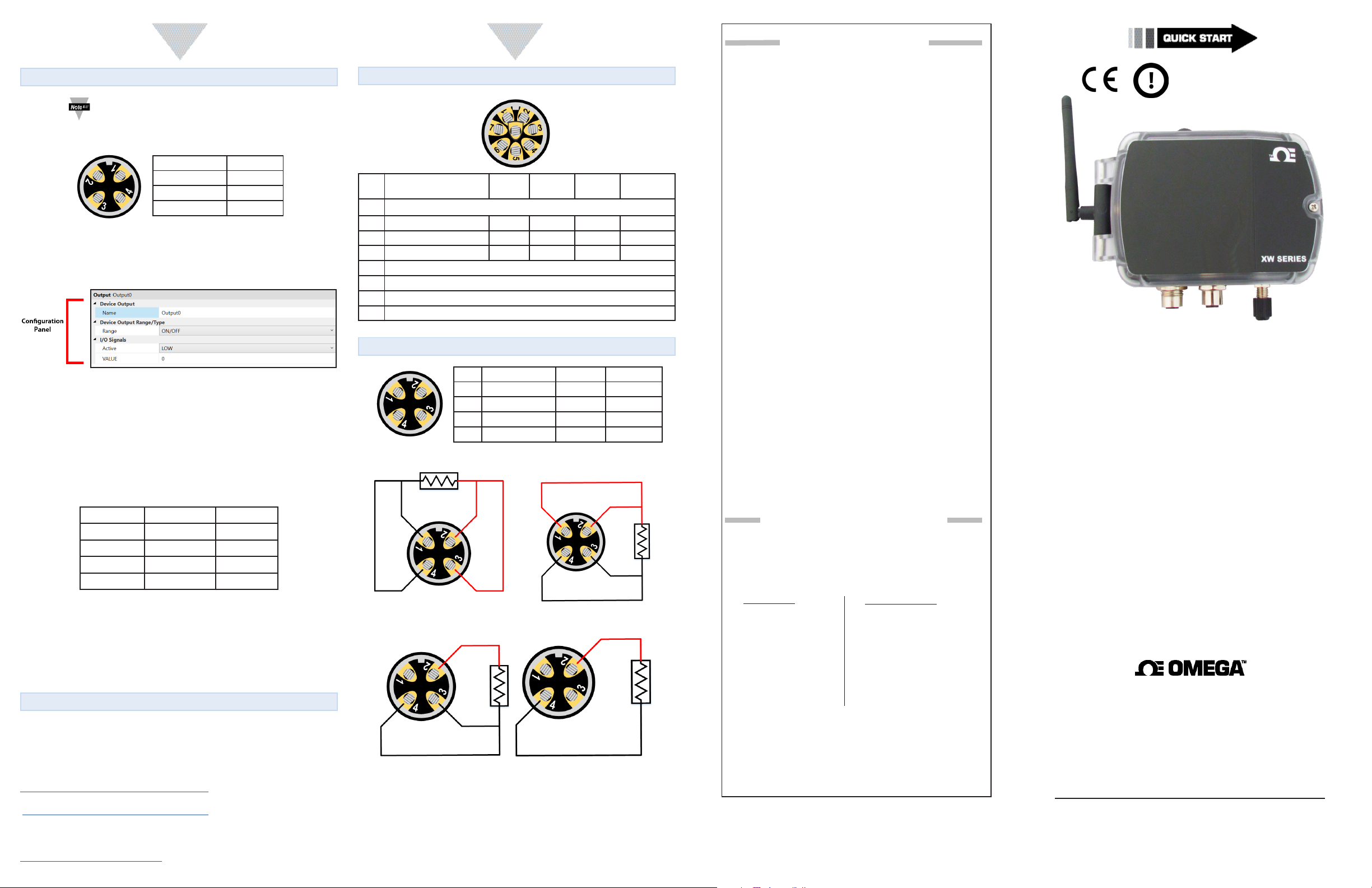
Discrete I/O Connector (PRO Version Only)
Note: Only PRO versions of the transmier support Discrete
I/O. Opons for these appear in the Output Tab in Omega
Sync. Please refer to the User’s Manual for more details on
how to congure I/O.
Pin 1 I/O 1
Pin 2 I/O 2
Pin 3 Ground 2
Pin 4 Ground 1
The XW-ED and XW-EDA-PRO versions support 2 Discrete Open Drain Digital
Inputs / Outputs on the 4-pin M12 Male connector. To connect an input or
output, a standard M12 4-pin cable can be used. Omega also oers an oponal
eld installable M12 connector.
Figure 10
Input
To use a pin as an input make sure it is set to Acve Low (default) in the Output
Conguraon Tab in Omega Sync. The Input can then be set as Acve High or
Low in the Input Tab.
Each pin has an internal pull-up but in order to save power, the internal pull-up is
only acve when unit takes a reading.
The state of both pins is always shown on the ZW-REC as the last input. Refer to
the following table to decode the input state.
Input 1 Input 0 Reading
Inacve Inacve 0
Inacve Acve 1
Acve Inacve 2
Acve Acve 3
Output
Output opons are set in the Output Conguraon Tab of Omega Sync. Each
output can be congured as either Acve High or Acve low.
To use a pin as an output rst set up the Output Opons and assign the output
to an Alarm using Omega Sync. Please see the full User’s Manual for an in depth
descripon on how to assign the output to an alarm.
What’s Next?
You may now navigate to the ZW-REC webpage. Your XW Transmier and the
data it is reading will now appear on the ZW-REC webpage.
For addional informaon on the features of the XW Transmier or the ZW-REC,
refer to the following User’s Manuals.
•XW Transmier:
hps://assets.omega.com/manuals/M5745.pdf
• ZW-REC:
hps://assets.omega.com/manuals/M5546.pdf
For long-term data logging and OPC integraon, consider using the Omega
Gateway Enterprise soware downloadable at:
hps://www.omega.com/en-us/oeg
6
XW-ED Input Connector
Frequency Pulse Width
Duty Cycle Counter
Pin 1
Pin 2 Enable Clock B Direcon Input 3 Proc Input 1
Pin 3 Clock Clock A Clock Input 1 Proc Input 2
Pin 4 Reset Reset Reset Input 2 N/C
Pin 5 Shield
Pin 6 NC
Pin 7 GND
Pin 8 3.3V Output
Delay
XW-EDA Input Connector
Thermocouple Voltage Current
Pin 1 TC 2 Negave Input 2 Input 1
Pin 2 TC 1 Posive Input 2 Input 2
Pin 3 TC 1 Negave Ground 2 Ground 2
Pin 4 TC 2 Posive Ground 1 Ground 1
RTD 4 Wire Opon 1 RTD 4 Wire Opon 2
RTD 3 Wire RTD 2 Wire
Up/Down
Counter
NC
Digital
Input
Process
Input
WARRANTY/DISCLAIMER
OMEGA ENGINEERING, INC. warrants this unit to be free of defects
in materials and workmanship for a period of 13 months from
date of purchase. OMEGA’s WARRANTY adds an additional one (1)
month grace period to the normal one (1) year product warranty
to cover handling and shipping time. This ensures that OMEGA’s
customers receive maximum coverage on each product.
If the unit malfunctions, it must be returned to the factory for evaluation. OMEGA’s Customer Service Department will issue an Authorized
Return (AR) number immediately upon phone or written request.
Upon examination by OMEGA, if the unit is found to be defective, it
will be repaired or replaced at no charge. OMEGA’s WARRANTY does
not apply to defects resulting from any action of the purchaser, including but not limited to mishandling, improper interfacing, operation
outside of design limits, improper repair, or unauthorized modification. This WARRANTY is VOID if the unit shows evidence of having
been tampered with or shows evidence of having been damaged as a
result of excessive corrosion; or current, heat, moisture or vibration;
improper specification; misapplication; misuse or other operating
conditions outside of OMEGA’s control. Components in which wear
is not warranted, include but are not limited to contact points, fuses,
and triacs.
OMEGA is pleased to offer suggestions on the use of its various products. However, OMEGA neither assumes responsibility for any omissions or errors nor assumes liability for any
damages that result from the use if its products in accordance
with information provided by OMEGA, either verbal or written. OMEGA warrants only that the parts manufactured by
the company will be as specified and free of defects. OMEGA
MAKES NO OTHER WARRANTIES OR REPRESENTATIONS OF
ANY KIND WHATSOEVER, EXPRESSED OR IMPLIED, EXCEPT
THAT OF TITLE, AND ALL IMPLIED WARRANTIES INCLUDING
ANY WARRANTY OF MERCHANTABILITY AND FITNESS
FOR A PARTICULAR PURPOSE ARE HEREBY DISCLAIMED.
LIMITATION OF LIABILITY: The remedies of purchaser set
forth herein are exclusive, and the total liability of OMEGA
with respect to this order, whether based on contract, warranty, negligence, indemnification, strict liability or otherwise,
shall not exceed the purchase price of the component upon
which liability is based. In no event shall OMEGA be liable for
consequential, incidental or special damages.
CONDITIONS: Equipment sold by OMEGA is not intended to be used,
nor shall it be used: (1) as a “Basic Component” under 10 CFR 21 (NRC),
used in or with any nuclear installation or activity; or (2) in medical applications or used on humans. Should any Product(s) be used in or with
any nuclear installation or activity, medical application, used on humans,
or misused in any way, OMEGA assumes no responsibility as set forth
in our basic WARRANTY/DISCLAIMER language, and, additionally,
purchaser will indemnify OMEGA and hold OMEGA harmless from any
liability or damage whatsoever arising out of the use of the Product(s)
in such a manner.
RETURN REQUESTS/INQUIRIES
Direct all warranty and repair requests/inquiries to the OMEGA
Customer Service Department. BEFORE RETURNING ANY
PRODUCT(S) TO OMEGA, PURCHASER MUST OBTAIN AN
AUTHORIZED RETURN (AR) NUMBER FROM OMEGA’S CUSTOMER
SERVICE DEPARTMENT (IN ORDER TO AVOID PROCESSING
DELAYS). The assigned AR number should then be marked on the
outside of the return package and on any correspondence.
FOR WARRANTY RETURNS,
please have the following
information available BEFORE
contacting OMEGA:
1. Purchase Order number
under which the product
was PURCHASED,
2. Model and serial number of the
product under warranty, and
3. Repair instructions and/or
specific problems relative
to the product.
OMEGA’s policy is to make running changes, not model changes,
whenever an improvement is possible. This affords our customers
the latest in technology and engineering.
OMEGA is a trademark of OMEGA ENGINEERING, INC.
© Copyright 2019 OMEGA ENGINEERING, INC. All rights reserved.
This document may not be copied, photocopied, reproduced,
translated, or reduced to any electronic medium or machine-readable
form, in whole or in part, without the prior written consent of OMEGA
ENGINEERING, INC.
MQS5811/0819
FOR NON-WARRANTY REPAIRS,
consult OMEGA for current repair
charges. Have the following
information available BEFORE
contacting OMEGA:
1. Purchase Order number to cover
the COST of the repair or
calibration,
2. Model and serial number of the
product, and
3. Repair instructions and/or specific
problems relative to the product.
XW-ED, XW-ED-PRO, XW-EDA,
XW-EDA-PRO
XW Series Transmitter
omega.com [email protected]
U.S.A. Omega Engineering, Inc.
Headquarters: 800 Connecticut Ave. Suite 5N01, Norwalk, CT 06854
Toll-Free: 1-800-826-6342 (USA & Canada only)
Customer Service: 1-800-622-2378 (USA & Canada only)
Engineering Service: 1-800-872-9436 (USA & Canada only)
Tel: (203) 359-1660 Fax: (203) 359-7700
e-mail: [email protected]
For Other Locations Visit omega.com/worldwide
The information contained in this document is believed to be correct, but
OMEGA accepts no liability for any errors it contains, and reserves the right to
alter specifications without notice.
Servicing North America:
Page 2
START HERE
2
3
4
Introducon
Use this Quick Start Guide to set up your XW Transmier. For addional
informaon on all setup opons, refer to the User’s Manual available on the
Omega website.
Transmier Versions Descripon
XW-ED 8-Pin Digital Probes, Timer/Totalizer, Process
XW-ED-PRO
8-Pin Digital Probes, Timer/Totalizer, Process,
Discrete I/O
XW-EDA TC, RTD, Process
XW-EDA-PRO TC, RTD, Process, Discrete I/O
Materials
Included with your XW Transmier
•2.4 GHz Antenna
•Mounng Kit
•CR2032 Coin Cell Baery (Pre-Installed)
•2x C-Cell Baeries
•Micro USB Cable
•Quick Start Guide
Addional Materials Needed
•Computer/Laptop with Windows OS
•Omega Sync soware
(Downloadable on the Omega website)
•ZW-REC
•Micro USB Cable
Note: A second Micro USB cable is needed to connect the ZW-REC
to your computer.
Safety and Regulatory Compliance
Safety:
EN 61010-1 3rd Edion
EMC:
EN61326-1: 2013
Radio:
EN 301 489-17 V3.3.1
EN 300 328 V2.1.1:2016-11
CE:
The product herewith complies with the essenal requirements and other
relevant provisions of the Radio Equipment Direcve 2014/53/EU, the EMC
Direcve 2014/30/EU, and the Low Voltage Direcve 2014/35/EU, and carries the
CE-Marking accordingly.
Before You Start
To setup your XW Transmier, ensure the Omega Sync soware is downloaded,
setup, and running before connuing.
Connecng Your ZW-REC
Before connuing, make sure your ZW-REC is setup. Follow these direcons to
ensure your ZW-REC is properly connected.
Note: For a complete guide on how to set up your ZW-REC, refer to
the Quick Start Guide available on the Omega website.
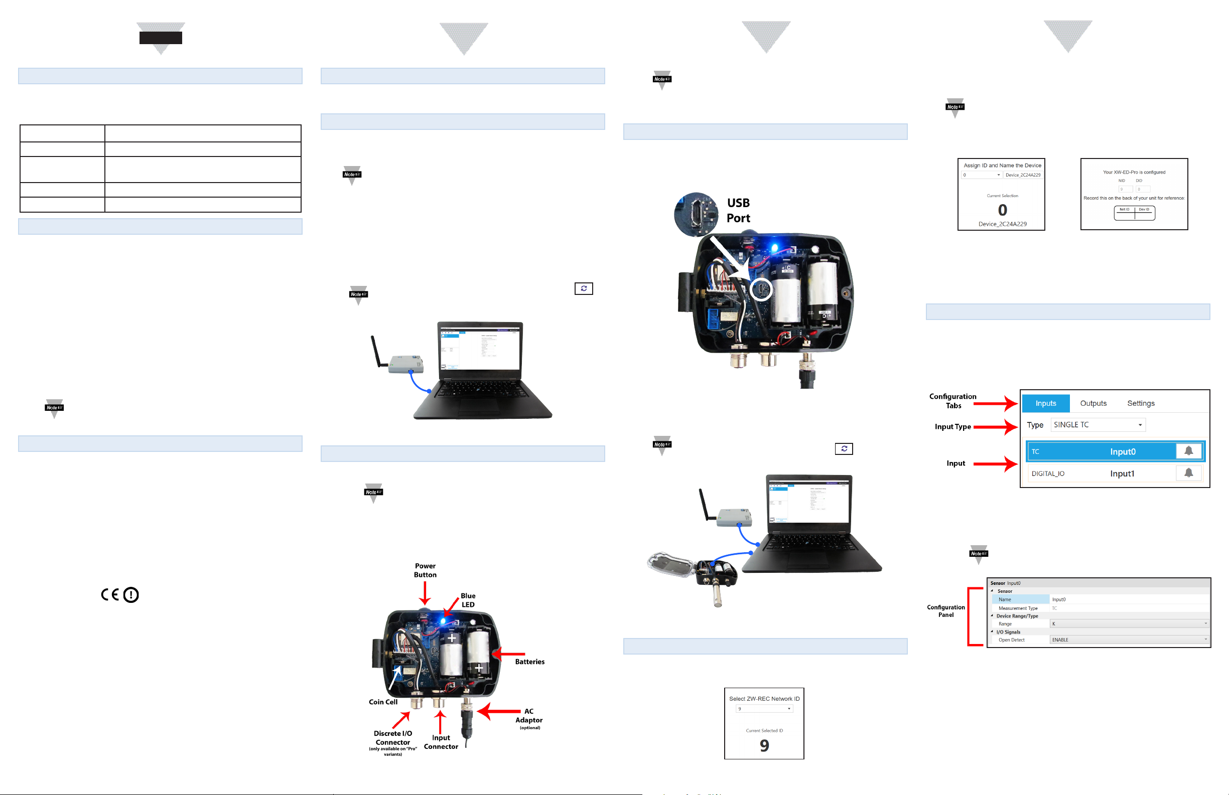
Step 1: Plug in your ZW-REC to your computer with a Micro USB cable. Omega
Sync will then auto-detect the ZW-REC and pull the following informaon from
the ZW-REC to ensure proper communicaon between the receiver and the
transmier:
•IP Address
•Network Mask
•Gateway
•PAN ID
Note: If the auto-detect feature is unsuccessful, click the
buon on Omega Sync to search for connected devices.
USB
Connection
Figure 1
Seng Up Your XW Transmier
Step 1: Connect the antenna to the XW Transmier.
Note: 8-pin digital probes, including Omega Smart Probes, can
be plugged in at this point. Digital I/O or Analog connecons
should be made aer the XW Transmier is setup.
Step 2: Remove the pull-tab from the coin cell. See Figure 2.
Step 3: Install the baeries or plug in the oponal AC Adaptor. See Figure 2.
Note: Take note of the baery orientaon of the device as
displayed in Figure 2.
The blue LED will illuminate immediately and begin ashing, indicang the device
is on.
Connecng to Omega Sync
Step 1: Ensure the XW Transmier is powered on.
Step 2: Connect the XW Transmier to your computer using a Micro USB cable.
Figure 3
You should now have your ZW-REC and your XW Transmier connected to the
computer running Omega Sync. See Figure 4.
Note: Omega Sync will auto detect your XW Transmier. If the
auto-detect feature is unsuccessful, click the buon on
Omega Sync to search for connected devices.
USB
Connection
USB
Connection
Step 2: Omega Sync will detect the Network ID of the connected ZW-REC. See
Figure 5. Click Next to accept network ID.
Note: The default Network ID for the ZW-REC is set to 0. You may
manually enter the Network ID of a dierent ZW-REC if the receiver
you wish to connect to is not available.
Step 3: Assign a unique Device ID and a name to your device. Click Next to
proceed. See Figure 6.
Figure 6
Step 4: Review your selecons and click Finish. Record your network ID selecon
on the back of the transmier.
If you are using a Digital or Smart Probe, setup is now complete. Please proceed
to the next secon to customize inputs.
Figure 7
Customizing Inputs
Click Inputs from the Conguraon Tabs to begin customizing your transmier.
See Figure 8.
Select the desired type from the Input Type drop-down menu. See Figure 8.
Figure 8
The desired Input (Figure 8) and the Conguraon Panel (Figure 9) will appear
below the drop down menu once it has been selected.
Note: If your transmier supports mulple inputs, click on the
one you wish to congure.
The following CE Mark is axed to this equipment.
The CE declaraon is available at the website listed on the cover page of this quick
start guide.
FCC/IC:
Part 15C, Class DTS Internaonal radiator
Contains TX FCC ID: TYOJN5168M5
Contains Industry Canada ID IC: 7438A-CYO5168M5
FCC Radiaon Exposure Statement:
This portable equipment with its antenna complies with FCC’s RF radiaon
exposure limits set forth for an uncontrolled environment. To maintain
compliance, follow the instrucons below:
1. This transmier must not be co-located or operang in conjuncon with any
other antenna or transmier.
2. Avoid direct contact to the antenna or keep it to a minimum while using this
equipment.
Figure 2
Figure 4
Onboarding the XW Transmier
Step 1: Once the XW Transmier is auto-detected, Omega Sync will guide you
through an Onboarding sequence.
Figure 5
Figure 9
You may use the conguraon panel to customize the available inputs on your
XW Transmier. For more details on the inputs available on your XW Transmier,
see the User’s Manual available on the Omega website.
Refer to the wiring diagrams in Secon 6 to connect your input.
 Loading...