

Page 1
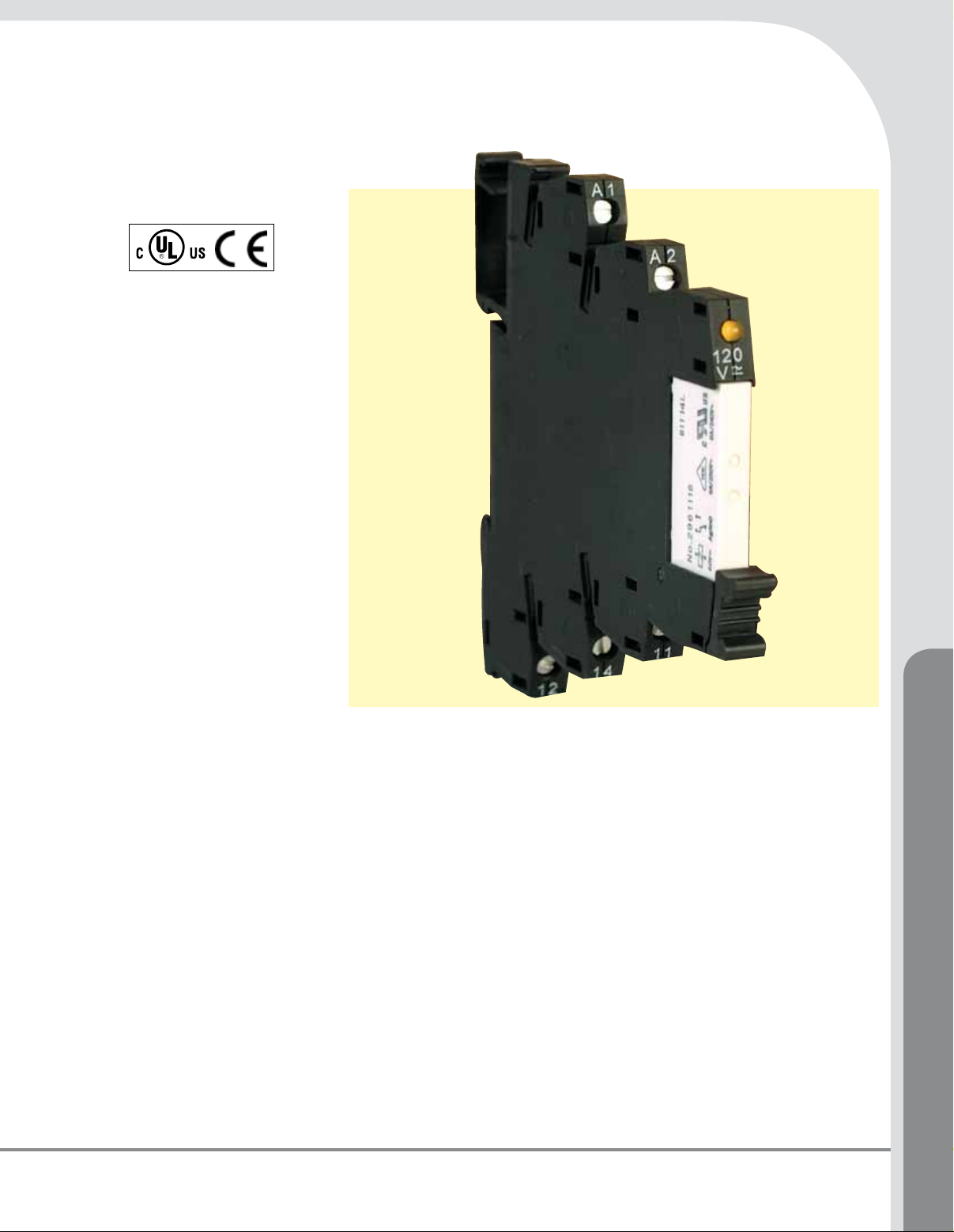
Standard terminal
Block relayS
XRU1D Series
l Pluggable Relay Allows for
Field Replacement
l Functional Plug-In Bridges
l Screw Connections
l LED Status Indication
l DIN Rail Mount
l Only 6.2 mm (0.24") Wide
l All Common Input Voltages
Between 24 Vdc to 120 Vac
l NEMA 6 (IP67) Protection
l Environmentally Friendly,
Cadmium-Free Contact
l Easy, Cost-Effective and
Replacement Using
Engagement Lever
The XR Series Terminal Block Relays are
ideal for applications that require a high
switching capacity and long electrical service
life. The relays are plug-in interfaces that
connect to basic terminal blocks. The XR
Series utilizes screw technology, as well as
offers quick system wiring, superior safety
features, clear labeling and a high level of
modularity.
Application Description
Used in automation systems,
electromechanical relays guarantee a
safe connection between process I/O and
electronic controls. The following functions
are covered by relay coupling elements:
l Electrical isolation between the
input and output circuits
l Independence of the type of
switching current (AC and DC)
l High short-term overload
resistance in the event of short
circuits or voltage peaks
l Low switching losses
l Ease of operation
Accessories
Power Terminal Block
The XRAPLCESK power terminal block has the
same shape as the relay modules and is used
to feed in the bridging potentials. The nominal
current is 32 A. When the total current is less
than or equal to 6 A, supply can take place
directly at the connecting terminal blocks of
one of the connected relays.
End Cover
The XRAATPBK end cover is required at the
start and stop of a relay strip. It can also be
used for visual separation of groups of relays
as well as separating relays with voltages
greater than 250V and separating neighboring
bridges with different potentials. It is equipped
with pre-scored break out points at the
bridging positions so that individual bridges
can be passed through as needed. It may also
XRU1D120U shown larger
than actual size.
be necessary to use the end cover between
adjacent relays when three phases (L1, L2,
L3) are used on the contact side of the relay.
Bridges
The XRAFBST colored, insulated plugin
bridge system reduces wiring time by up
to 70% compared to conventionally wired
relays. The XRAFBST2, 2-position bridges,
are suited for bridging a smaller number of
relays and total currents <6 A. When a circuit
is supplied from both sides, the circuit can
be opened at any point, allowing all other
modules to continue being supplied at the
same time. The XRAFBST500 allow up to
80 modules to be bridged at one time.
If bridges with different potentials meet
in neighboring modules, the end cover
XRAATPBK should be used. All bridges are
equipped with a groove for removal with a
standard screwdriver.
Relays and Timers
1
Page 2
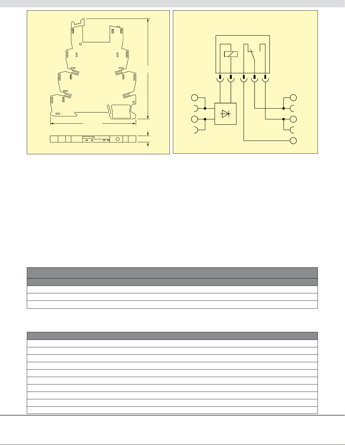
Dimensions:
mm (in)
Schematic for standard
terminal block relays
94 (3.70)
80 (3.15)
SPECIFICATIONS
Input Voltage:
XRU1D24: 24 Vdc
XRU1D24U: 24 Vac/Vdc
XRU1D120U: 120 Vac/110 Vdc
Typical Input Current:
XRU1D24: 9 mA
XRU1D24U: 11 mA (24 Vac),
8.5 mA (24 Vdc)
XRU1D120U: 3.5 mA (120 Vac),
3 mA (110 Vdc)
Connection Type: Screw connection
Rigid Solid AWG (mm2): 26 to 14
(0.14 to 2.5)
Flexible Stranded AWG (mm2):
26 to 14 (0.14 to 2.5)
A2
A1
6.2 (0.24)
Typical Response Time:
XRU1D24: 5 mS
XRU1D24U and XRU1D120U: 6 mS
Typical Release Time:
XRU1D24: 8 mS
XRU1D24U and XRU1D120U: 15 mS
Input Protection:
XRU1D24: Polarity protection diode,
free-wheeling diode
XRU1D24U and XRU1D120U:
Bridge rectifier
Contact Type: 1 PDT
Contact Material: AgSnO
Max Switching Voltage: 250 Vac/Vdc
1
Min Switching Voltage: 12 Vac/Vdc
Limiting Continuous Current: 6 A
Min Switching Current: 10 mA
Min Switching Power: 120 mW
Ambient Temp Range: -20 to 60°C
(-4 to 140°F)
Rated Operating Mode:
100% operating factor
Inflammability Class:
V0, in accordance with UL 94
Mechanical Service Life:
7
cycles
2 x 10
1 The separating plate, XRAPLCESK, should
be installed for voltages greater than 250V
(L1, L2, L3) between identical terminal points
of adjacent modules. Potential bridging is
then possible with the XRAFBST bridge
system.
11
14
12
To Order
MODEL NO. DESCRIPTION
XRU1D120U 1 PDT relay, 120 Vac/110 Vdc coil voltage
XRU1D24 1 PDT relay, 24 Vdc coil coltage
XRU1D24U 1 PDT relay, 24 Vac/Vdc coil voltage
Ordering Example: XRU1D120U, 1 PDT relay.
REPLACEMENT RELAYS AND ACCESSORIES
MODEL NO. DESCRIPTION
XRR1D120U Replacement relay for XRU1D120U
XRR1D24 Replacement relay for XRU1D24 and XRU1D24U
XRAPLCESK Power terminal block
XRAATPBK Black end cover
XRAFBST2RD 2-position red snap in jumper
XRAFBST2BU 2-position blue snap in jumper
XRAFBST2GY 2-position gray snap in jumper
XRAFBST500RD 80-position red snap in jumper
XRAFBST500BU 80-position blue snap in jumper
XRAFBST500GY 80-position gray snap in jumper
2
 Loading...