

Page 1
WARRANTY/DISCLAIMER
OMEGA ENGINEERING, INC. warrants this unit to be free of defects
in materials and workmanship for a period of 13 months from
date of purchase. OMEGA’s WARRANTY adds an additional one (1)
month grace period to the normal one (1) year product warranty
to cover handling and shipping time. This ensures that OMEGA’s
customers receive maximum coverage on each product.
If the unit malfunctions, it must be returned to the factory for
evaluation. OMEGA’s Customer Service Department will issue an
Authorized Return (AR) number immediately upon phone or written
request. Upon examination by OMEGA, if the unit is found to be
defective, it will be repaired or replaced at no charge. OMEGA’s
WARRANTY does not apply to defects resulting from any action of
the purchaser, including but not limited to mishandling, improper
interfacing, operation outside of design limits, improper repair,
or unauthorized modification. This WARRANTY is VOID if the unit
shows evidence of having been tampered with or shows evidence of
having been damaged as a result of excessive corrosion; or current,
heat, moisture or vibration; improper specification; misapplication;
misuse or other operating conditions outside of OMEGA’s control.
Components in which wear is not warranted, include but are not
limited to contact points, fuses, and triacs.
OMEGA is pleased to offer suggestions on the use of its various
products. However, OMEGA neither assumes responsibility for
any omissions or errors nor assumes liability for any damages
that result from the use if its products in accordance with
information provided by OMEGA, either verbal or written.
OMEGA warrants only that the parts manufactured by the
company will be as specified and free of defects. OMEGA
MAKES NO OTHER WARRANTIES OR REPRESENTATIONS OF
ANY KIND WHATSOEVER, EXPRESSED OR IMPLIED, EXCEPT
THAT OF TITLE, AND ALL IMPLIED WARRANTIES INCLUDING
ANY WARRANTY OF MERCHANTABILITY AND FITNESS
FOR A PARTICULAR PURPOSE ARE HEREBY DISCLAIMED.
LIMITATION OF LIABILITY: The remedies of purchaser set forth
herein are exclusive, and the total liability of OMEGA with
respect to this order, whether based on contract, warranty,
negligence, indemnification, strict liability or otherwise,
shall not exceed the purchase price of the component upon
which liability is based. In no event shall OMEGA be liable for
consequential, incidental or special damages.
CONDITIONS: Equipment sold by OMEGA is not intended to be used,
nor shall it be used: (1) as a “Basic Component” under 10 CFR 21 (NRC),
used in or with any nuclear installation or activity; or (2) in medical
applications or used on humans. Should any Product(s) be used in or
with any nuclear installation or activity, medical application, used on
humans, or misused in any way, OMEGA assumes no responsibility
as set forth in our basic WARRANTY/DISCLAIMER language, and,
additionally, purchaser will indemnify OMEGA and hold OMEGA
harmless from any liability or damage whatsoever arising out of the use
of the Product(s) in such a manner.
RETURN REQUESTS/INQUIRIES
Direct all warranty and repair requests/inquiries to the OMEGA
Customer Service Department. BEFORE RETURNING ANY
PRODUCT(S) TO OMEGA, PURCHASER MUST OBTAIN AN
AUTHORIZED RETURN (AR) NUMBER FROM OMEGA’S CUSTOMER
SERVICE DEPARTMENT (IN ORDER TO AVOID PROCESSING
DELAYS). The assigned AR number should then be marked on the
outside of the return package and on any correspondence.
FOR WARRANTY RETURNS,
please have the following
information available BEFORE
contacting OMEGA:
1. Purchase Order number under
which the product was
PURCHASED,
2. Model and serial number of
the product under warranty, and
3. Repair instructions and/or
specific problems relative to
the product.
OMEGA’s policy is to make running changes, not model changes,
whenever an improvement is possible. This affords our customers
the latest in technology and engineering.
OMEGA is a registered trademark of OMEGA ENGINEERING, INC.
© Copyright 2014 OMEGA ENGINEERING, INC. All rights reserved.
This document may not be copied, photocopied, reproduced,
translated, or reduced to any electronic medium or machine-readable
form, in whole or in part, without the prior written consent of OMEGA
ENGINEERING, INC.
MQS4360/0114
FOR NON-WARRANTY REPAIRS,
consult OMEGA for current repair
charges. Have the following
information available BEFORE
contacting OMEGA:
1. Purchase Order number to
cover the COST of the repair or
calibration,
2. Model and serial number of the
product, and
3. Repair instructions and/or specific
problems relative to the product.
5
Correction Factors
For Hot Wire Anemometers:
If the environmental conditions are other than the
standard conditions (70°F and 29.92 inches of Hg), you
need to correct for them. Here is the correction factor
equation:
K1 = (29.92 / P) x (460 + T) / 530
where…
P is the Barometric pressure in inches of Hg
T is the ambient temperature in Degree
There is a second correction factor which is a function of
the air probe geometry (K2).
The following table lists K2 for different air probes. So,
the actual air velocity is as follows:
Actual Value = Measure Value (average value over one
minute time) x K1 x K2
For Vane Type Anemometers:
You only need to correct for the air probe geometry
(K2). The actual air velocity is as follows:
Actual Value = Measured Value (Average value over
one minute time) x K2
Correction Factor Example:
An FMA-904 Hot wire anemometer is being checked in
the Wind Tunnel at 2.5 m/s (492 FPM) air speed.
The environmental conditions are:
Barometric Pressure = 27.88 inches of Hg
Ambient Temperature = 80°F
The FMA-904 measures 442 FPM. Calculate the actual
air speed:
Actual Air speed = Measured Value (Average value over
one minute) x K1 x K2
K1 = (29.92/P) x (460 + T)/530
K1 = (29.92/27.88) x (460 + 80)/530
K1 = 1.093
From Correction Factor – K2 Chart, K2 for FMA904 @
2.5 m/s is 1.04
Actual Air speed = 442 x 1.093 x 1.04
Actual Air speed = 502 FPM
Specifications
Accuracy: ±1% of setting or ±0.1 m/s, whichever is
larger
Test Chamber: 10 cm (4") diameter
6
For complete product manual:
www.omega.com/manuals/manualpdf/M4360.pdf
Anemometer
Sold Separately
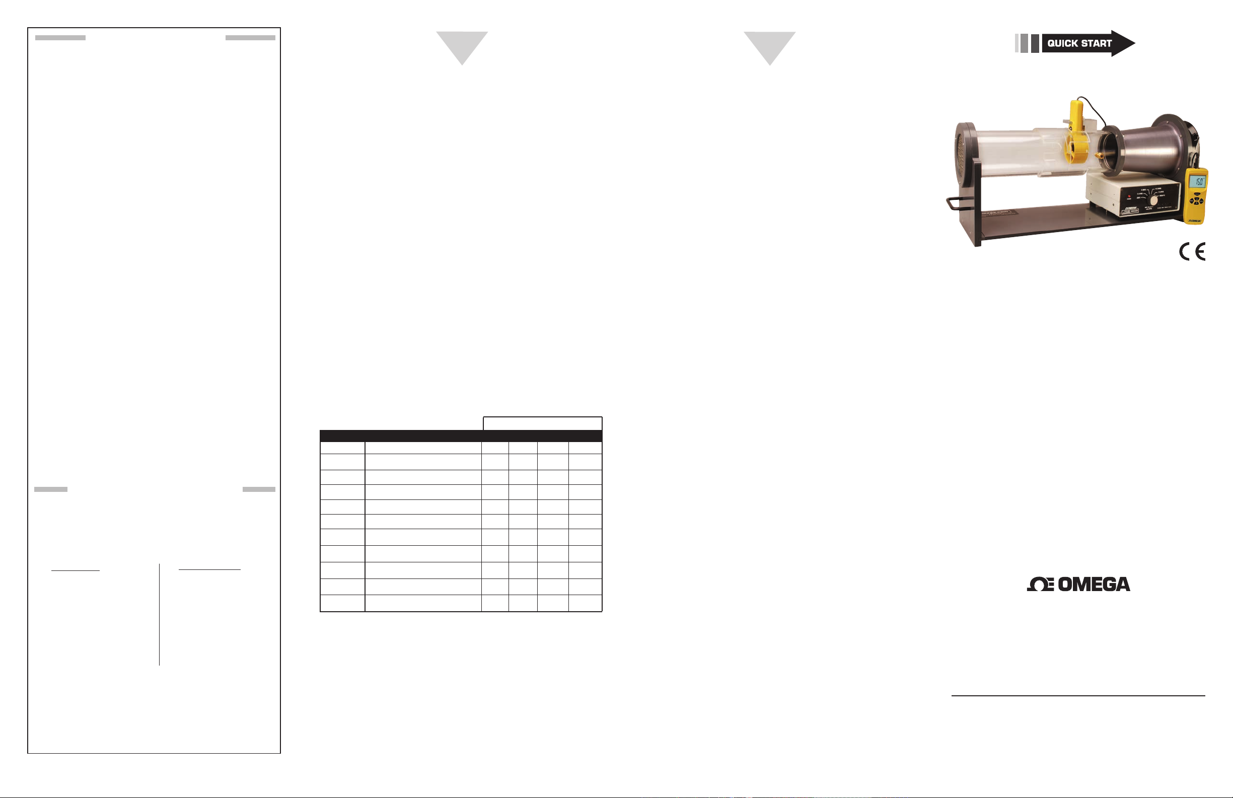
WTM-1000
Laboratory Grade
Bench Top Mini Wind Tunnel
Flow Rates: 2.5 m/s (492 fpm), 5.0 m/s (984 fpm),
10 m/s (1969 fpm), 15 m/s (2953 fpm)
Correction Factor - K2
Model No. D
FPM-904 Hot Wire 0-2000 FPM 1.04 1.00 1.01 N/A
FMA-905 Hot Wire 0-5000 FPM 1.00 1.00 1.01 1.04
HHF42 Hot Wire 40-3940 FPM 1.04 1.00 1.06 1.07
HHF801 Vane Type 160-2358 FPM 1.08 1.12 1.17 N/A
HHF802 Vane Type 80-4930 FPM 0.90 0.96 1.04 1.07
HHF803 Vane Type 160-4930 FPM 0.94 1.00 1.09 1.06
HHF91 Vane Type 125-4900 FPM 0.86 0.92 1.00 1.03
HHF92A Vane Type 80-6900 FPM 0.92 0.97 1.05 1.04
HHF81 Vane Type 80-5910 FPM 1.03 1.06 1.13 1.12
HHF82 Vane Type 80-5910 FPM 1.14 1.18 1.24 1.22
HHF11 Vane Type 80-6900 FPM 0.88 0.90 0.99 1.01
escription
@ 2.5 m/s @5 m/s @10 m/s @15 m/s
Remote Option: Use an external 5K, 10-turn
potentiometer to vary air speed
DC Motor: 24 Vdc @ 1.1 A (26 W)
Power: 90 to 250 Vac @ 50/60 Hz
Operating Temperature: 5 to 45°C (41 to 113°F)
Operating Relative Humidity: 80% RH max without
condensation
Size: 68.5 L x 20.3 W x 29.2 cm H (27 x 8 x 11.5")
Weight: 8.2 kg (18 lb)
®
omega.com [email protected]
Servicing North America:
U.S.A.: OMEGA Engineering, Inc., One Omega Dr.
P.O. Box 4047, Stamford, CT 06905-0047 USA
Toll-Free: 1-800-826-6342 (USA & Canada Only)
Customer Service: 1-800-622-2378 (USA & Canada Only)
Engineering Service: 1-800-872-9436 (USA & Canada Only)
Tel: (203) 359-1660 Fax: (203) 359-7700
e-mail: [email protected]
For Other Locations Visit omega.com/worldwide
It is the policy of OMEGA Engineering, Inc. to comply with all worldwide safety
and EMC/EMI regulations that apply. OMEGA is constantly pursuing certification of
its products to the European New Approach Directives. OMEGA will add the CE
mark to every appropriate device upon certification.
The information contained in this document is believed to be correct, but
OMEGA accepts no liability for any errors it contains, and reserves the right to
alter specifications without notice.
WARNING: These products are not designed for use in, and should not be used
for, human applications.
Page 2
START HERE
EXHAUST END VIEW IN-TAKE END VIEW FRONT VIEW
69.85
POWER LED
CONNECT TO EXTERNAL
2
3
4
Using This Quick Start Manual
Use this Quick Start Manual with your WTM-1000
Laboratory Grade, Bench Top Mini Wind Tunnel
for quick installation and basic operation. For
detailed information, refer to the User’s Guide
(Manual M4360).
General Information
e Mini Wind Tunnel Model WTM-1000 is
designed to give a highly uniform ow rate over a
10cm (4") diameter test chamber. e Wind Tunnel
has an electronic control unit where it controls the
DC Fan speed and provides four selectable xed air
speeds. e xed air speeds are:
• 2.5 m/s (492 FPM)
• 5 m/s (984 FPM)
• 10 m/s (1969 FPM)
• 15 m/s (2953 FPM)
In addition, there is a REMOTE selection on the
electronic control unit selector switch. This will
allow connecting an external potentiometer to
control the DC fan speed and be able to vary
the speed from 0 to 15 m/s. A cable to connect
an external potentiometer to the control unit is
included in the shipping box.
NOTE:
Use an external 5K, 10-turn potentiometer.
Setting Up the Mini Wind Tunnel
Precautions:
A wind tunnel’s performance can be severely
diminished if not used properly. Please follow the
following tips:
• Do not use the wind tunnel in small rooms. The
air flow creates currents that undermine the
wind tunnel’s accuracy.
• Avoid locating the intake and exhaust toward
open windows, doorways or corridors where
people are walking. The effect of air current
changes across the intake has a severe effect on
the flow rate changing in the wind tunnel.
• There should be at least 1.5 m (5 feet) clear
space in front of and behind the wind tunnel.
No obstacles, moving objects, open doors or
windows.
• Locate the exhaust towards the largest open area of
the room to minimize room air currents. The higher
the flow rate, the more chance of creating currents.
• Air Probe geometry affects the readings. There is a
correction factor table for different types of air probes
(Hot wire & Vane type).
• The air flow rate of the wind tunnel depends on the
air temperature and barometric pressure. Adjust it
accordingly.
• This instrument should only be used for its intended
purpose in accordance to the instruction manual.
Operating the Wind Tunnel
Before operating the wind tunnel, please follow all the
precautions stated in the previous section and then
proceed as follows:
1. Connect the cable from the DC Fan to the back of the
Control unit box labeled ‘Fan Control’. Make sure the
power switch in the back of the control unit is off.
2. Connect the AC input of the Control unit to a line
voltage (90 to 250 VAC @ 50/60 Hz) with the Power
cord provided.
3. Set the air speed selector switch on the front of the
control unit to Zero position (Meaning Zero air
velocity). Turn on the Power switch in the back. You
will see the power LED indicator on the front of the
control box turns on.
The air speed selector switch can be set to four fixed air
speeds. The wind tunnel has been calibrated at these
four air speeds. The standard conditions are at 70°F
(21.2°C) ambient temperature and 29.92 inches of Hg
of Barometric pressure. There are four plugs in front of
the control unit box. Removing the plugs, you will have
access to potentiometers that will allow you to adjust the
air speed at the four settings.
For Hot Wire Anemometers:
1. Use the Chamber Door (Solid) to cover the test
chamber.
2. Insert the air probe into Port #1. Port #2 is used to
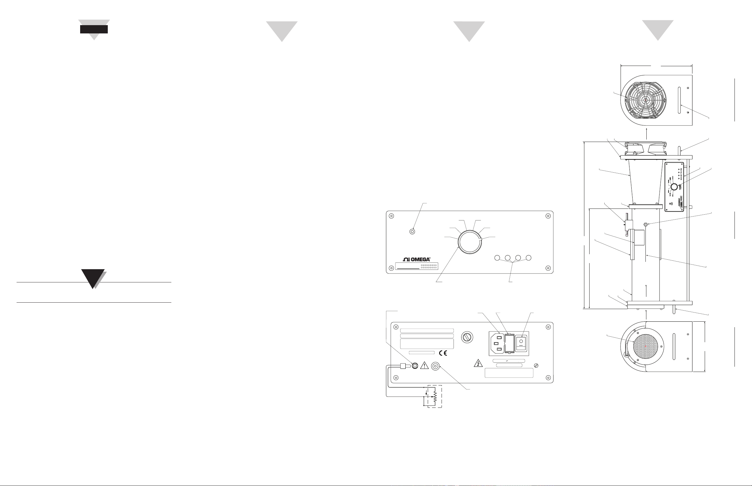
insert a reference air probe if desired. Refer to Front
View of WTM1000 for location of ports.
3. Align the air probe sensor to the center of the chamber
using the scribed line on the outside of the chamber.
4. Use the Teflon Ferrules and “hand-tighten” the probe
in place. Do not use tools or wrenches.
For Vane Type Anemometers:
1. Remove the chamber door. Open the clamp in the
adjustable mounting block by turning the wheel.
2. Place the vane propeller inside the chamber. Make
sure it is in the center of the chamber.
3. Place the vane window door.
4. Secure the vane propeller in place by tightening the
clamp using the wheel.
5. Slide the Vane Clamp sleeve over the vane window
door and up against the vane probe to minimize any
air leaks.
Once the air probe is in place (either Hot Wire or Vane
Type), turn the air speed selector switch from 2.5
m/s (492 FPM) up to 15 m/s (2953 FPM). Check the
air probe reading vs. the switch setting on the wind
tunnel.
10 (1969)
15 (2953)
CAUTION: FOR CONTINUED PROTECTION AGAINST
THE RISK OF FIRE REPLACE WITH ONLY THE SAME
TYPE, RATING AND SIZE OF FUSE. DISCONNECT
POWER FROM SOURCE BEFORE CHANGING FUSE.
CONNECT TO
DC FAN
REMOTE
2.5 m/s 5 m/s 10 m/s 15 m/s
CALIBRATION
ADJUSTMENTS
2 BUILT-IN
FUSES
0.5 A, 250 V
90-250 VAC 50/60 HZ, 50 W
FUSE: T0.5 A, 250 V
POWER
SWITCH
POWER
MINI WIND TUNNEL
WTM-1000 SERIES
POTENTIOMETER WITH
CABLE PROVIDED
(REMOTE OPTION)
MODEL NO: WTM-1000
SERIAL NO:
OMEGA ENGINEERING. INC.
STAMFORD. CT 06907-0047
1-800-826-6342 omega.com
MADE IN THE U.S.A.
REMOTE
CW- INCREASING AIR SPEED
5 (984)
2.5 (492)
ZERO
AIR VELOCITY
m/s (FPM)
AIR SPEED
SELECTOR SWITCH
Front Panel, Control Unit Box
AC INPUT
90-250 VAC
@50/60 Hz
FUSE
T3.15A 250 V
FAN CONTROL
CW
EXTERNAL
POTENTIOMETER
10 TURN
5W
Rear Panel, Control Unit Box
29.85
(11.75)
FAN GUARD
DIMENSIONS CM (IN.)
HANDLE
CARRYING
ELECTRONIC
CONTROL BOX
FAN SPEED
CONTROL
PROBE PORT #1 (FRONT)
PROBE PORT #2 (BACK)
SCRIBED
CENTERING
LINES ON 4 AXIS
CARRYING
HANDLE
20.96
(8.25)
1/4" COMPRESSION
FITTING BOTH PORTS
(27.5)
41.91
EXPANSION
VANE/PROBE
CLAMP SLEEVE
(16.5)
FAN MOUNTING LEG
DC FAN
CONE
ADJUSTABLE
PROBE/VANE
MOUNTING
BLOCK
TRANSITION
CHAMBER
DOOR
10.16 (4.0) DIAMETER
HONEYCOMB
INTAKE GUARD
INTAKE LEG
INTAKE
HONEYCOMB
EXHAUST
RING
TEST CHAMBER
AIR FLOW
INTAKE
Important Components of Mini Wind Tunnel and
Overall Dimensions
 Loading...