

Page 1
USER’S GUIDE
WT4401-S & WT4401-D
Benchtop Wind Tunnels
omega.com | [email protected]
For latest product manuals:
omega.com/en-us/pdf-manuals
TM
Page 2

CONTACT
Omega Engineering, Inc.
omega.com/contact-us
Toll-Free:
1-800-826-6342 (USA & Canada only)
Customer Service:
1-800-622-2378 (USA & Canada only)
Engineering Service:
1-800-872-9436 (USA & Canada only)
Telephone:
(203) 359-1660
Fax:
(203) 359-7700
Email: [email protected]
For other locations visit:
omega.com/worldwide
The information contained in this document is believed to be correct,
but Omega accepts no liability for any errors it contains, and reserves
the right to alter specifications without notice.
Page 3

Table of Contents
1. Introduction ..........................................................................................................................................................................4
1.1. Product Description ............................................................................................................................................................. 4
1.2. Unpacking ............................................................................................................................................................................... 5
2. Setting Up the Wind Tunnel ............................................................................................................................................6
2.1. Precautions .............................................................................................................................................................................6
2.2. Setup Procedure ................................................................................................................................................................... 6
3. Installing the Wind Tunnel ...............................................................................................................................................10
4. Operating Instructions .......................................................................................................................................................12
5. Calibrating at Other Flow Rates Not Listed in the Calibration Sheets ...............................................................13
6. Specifications ......................................................................................................................................................................14
7. In Case of Problems ..........................................................................................................................................................15
8. Maintenance .........................................................................................................................................................................15
9. Spare Parts and Replacement Parts ............................................................................................................................16
10. Appendix A: Differential Pressure Fluctuation Errors ...............................................................................................17
11. Appendix B: Barometric Pressure Calculations .........................................................................................................19
Table of Contents
3
Page 4
1. Introduction
1.1. Product Description
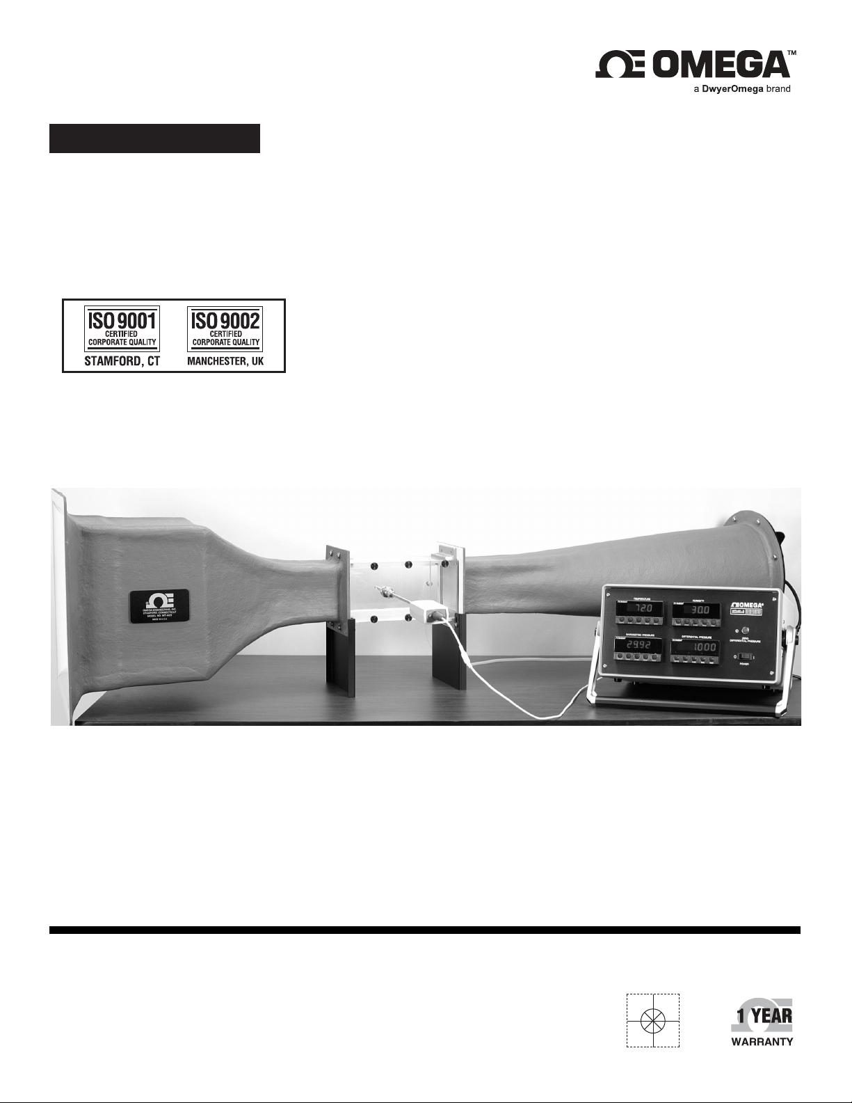
The WT4401-S and WT4401-D wind tunnels are designed to give a uniform ow rate over a 101.6 mm x 101.6
mm (4 in x 4 in) test cross section. A powerful 12 A motor varying from 0 RPM to 10,000 RPM is adjusted to
give a particular ow rate by a precision motor control unit. Once a known ow rate is established the air
probe under test is read or calibrated. Each wind tunnel is supplied with NIST traceable certicates. The
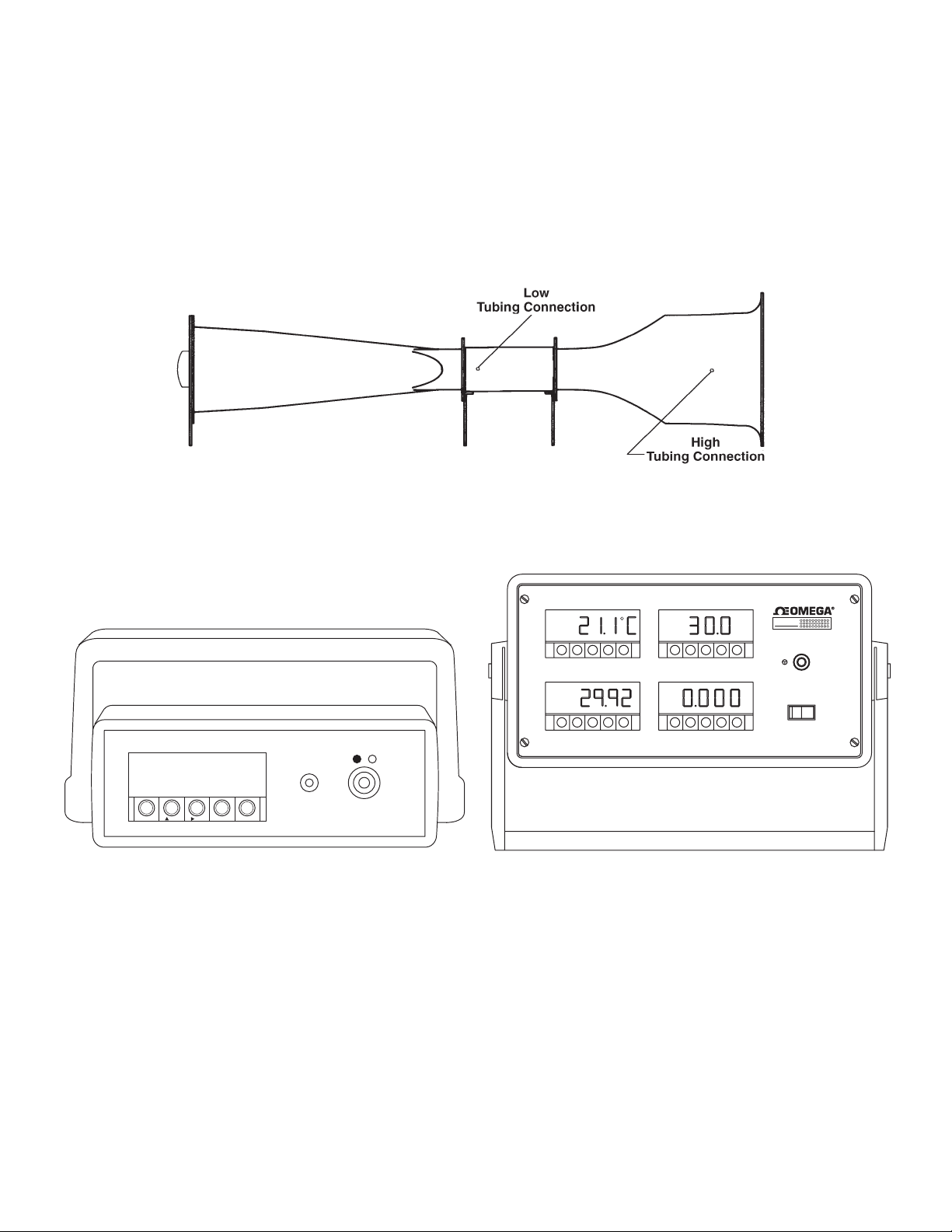
uniform ow rate is determined by monitoring a differential pressure between taps (tubing connections)
provided (refer to Figure 1). OMEGA offers a complete line of dif ferential pressure transducers. The one model
most commonly used with this wind tunnel is model PX657-5DI. Panel meters and bench top meters also
come with the wind tunnel in comprehensive electronics boxes. Figure 2 shows both types of electronics
boxes.
Figure 1: Location of Tubing Connections
TEMPERATURE
/
TARE
SETPTS /MIN/MAX MENU RESET
HUMIDITY
WT4401-D
DIFFERENTIAL PRESSUREBAROMETRIC PRESSURE
ZERO
DIFFERENTIAL PRESSURE
POWE
I
Figure 2: Standard Electronics Box(Left) and Deluxe Electronics Box (Right)
A differential pressure measurement used to establish known ow rates is affected by barometric pressure,
and temperature conditions during testing. Depending on the probe being calibrated, humidity might also
be a factor. OMEGA offers a complete system to monitor differential pressure, ambient barometric pressure,
ambient temperature, and ambient humidity conditions. Each wind tunnel is supplied with two restrictive plates
for achieving optimum lower ow rates. The established differential pressure measurements versus ow rates
are listed from 25 FPM to 9000 FPM. Calibration sheets are included to make calibrating different ow sensors
simple. An assortment of compression ttings is provided to help mount your probe under calibration.
This system features:
• Compact design to take up “little bench-top space”
• Precise motor control for adjusting ow rates
• NIST calibration sheets supplied with each wind tunnel
4 Benchtop Wind Tunnel
Page 5
• Highly accurate to 1% of reading
• Large 101.6 mm x 101.6 mm (4 in x 4 in) test chamber
• Highly stable delta pressure sensor and readout(s) included with each wind tunnel
• Optional environmental monitoring package of temperature, humidity, barometric pressure and delta
pressure available
1.2. Unpacking
Remove the Packing List and verify that you have received all equipment. If you have any questions about the
shipment, please call the OMEGA Customer Service Department at 1-800-622-2378 or (203) 359-1660.
When you receive the shipment, inspect the container and equipment for any signs of damage. Note any
evidence of rough handling in transit. Immediately report any damage to the shipping agent.
Note
The carrier will not honor any claims unless all shipping material is saved for their examination. After
examining and removing contents, save packing material and carton in the event reshipment is necessary.
If you ordered the WT4401-S you get:
• 1 Wind Tunnel
• 1 Electronics Box* (serial number must match the
serial number on the wind tunnel)
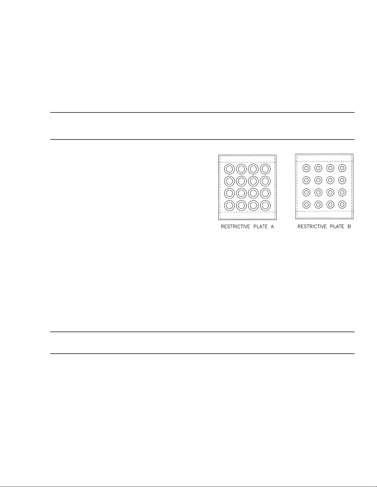
• 1 Restrictive Plate A
• 1 Restrictive Plate B
• 1 Motor Controller
• 2 5-foot pieces of Silicone Tubing
• 1 Package of Brass Compression Fittings with Teon
Ferrules (sizes - 3.175 mm [1⁄8 in], 4.762 [3⁄16 in],
6.35 mm [1⁄4 in], 9.525 mm [3⁄8 in])
• 6 Calibration Report Sheets (3 in metric units, 3 in
English units)
• 1 Operator’s Manual for DP41-S Indicator
• 1 Quick Reference Guide for the DP41-S Indicator
• 1 Operator’s Manual for the Motor Controller
• 1 Operator’s Manual for Wind Tunnel
Figure 3: Restrictive Plate A and B
If you ordered the WT-4401-D (deluxe system ) you also get the following items:
• 1 Operator’s Manual for DP25-E panel meter
• 1 Calibration Sheet for the barometer
If you ordered WT4401-S, you get the standard electronics box; if you ordered WT4401-D, you get the deluxe
electronics box.
Note
All meters used in either the standard or deluxe electronics package have a 10 V dc analog output.
5Introduction
Page 6

2. Setting Up the Wind Tunnel
2.1. Precautions
A wind tunnel’s performance can be severely diminished if not used with the following considerations in mind.
• Do not use the wind tunnel in small rooms with less than 1,800 cubic feet. The air ow creates currents
that undermine the wind tunnel’s accuracy.
• Avoid locating the intake and exhaust toward open windows, doorways or corridors where people
are walking. The effect of air current changes across the intake has a severe affect on the ow rate
changing in the wind tunnel.
• Locate the exhaust towards the largest open area of the room to minimize room air currents. Naturally
the higher the ow rate, the more chance of creating currents exists.
2.2. Setup Procedure
Refer to the table below for ow ranges.
Wind Tunnel Conguration Flow Ranges Accuracy
No restrictive plate used 1000 fpm to 7500 fpm 1 % reading
Restrictive Plate A used 250 fpm to 1500 fpm 2 % reading
Restrictive Plate B used 25 fpm to 300 fpm 2 % reading
After determining which ow range you wish to calibrate at, and whether you need a restrictive plate, go
through the following procedure to install it or remove it.
Flow Ranges
1. Remove two thumbscrews and remove the small plexiglass cover.
2. Inspect the gasket around the four sides of restrictive plate rst. The gasket should provide a good seal
when the plate is inserted into the slots. If not, replace it. It would be a good idea to have extra gaskets
on hand.
3. Slide restrictive plate into the slots in the center of the wind tunnel. Keep the at side upstream. Refer to
Figure 4 for the proper orientation of the restrictive plate. Or remove the plate if you don’t need it.
4. Replace plexiglass cover and screws.
Figure 5 shows the direction of air ow through one type of restrictive plate. Chapter 3 describes how to set
up the whole Wind Tunnel including the Electronics Instrument Box both of which are shown in Figures 6 and
Figure 7.
6 Benchtop Wind Tunnel
Page 7
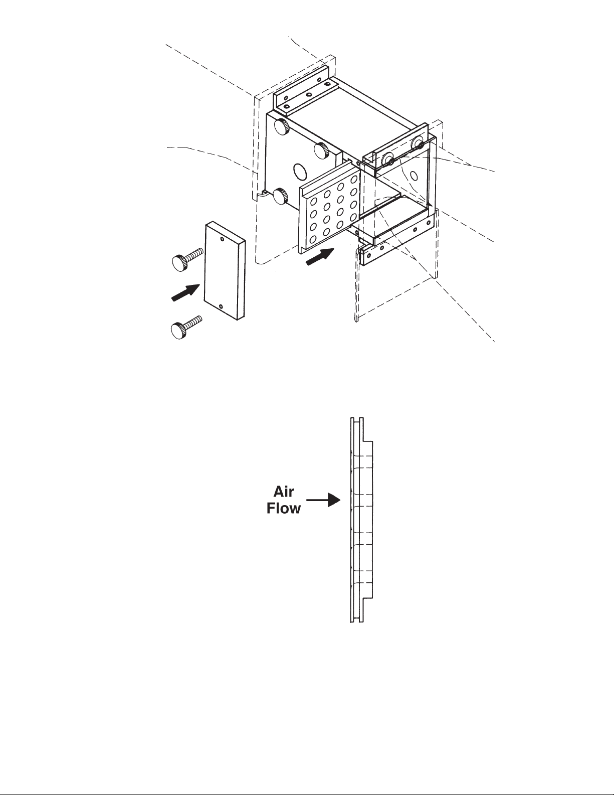
Figure 4: Restrictive Plate Placement
Figure 5: Air Flow
7Setting Up the Wind Tunnel
Page 8
TEMPERATURE
HUMIDITY
WT4401-D
TEM
RH-BAR+-DP
+
+-+-
DIFFERENTIAL PRESSUREBAROMETRIC PRESSURE
HIGH LO
CAUTION: FOR CONTINUED PROTECTION AGAINST
THE RISK OF FIRE REPLACE WITH ONLY THE SAME
TYPE, RATING AND SIZE OF FUSE. DISCONNECT
POWER FROM SOURCE BEFORE CHANGING FUSE.
MADE IN THE U.S.A.
MODEL NO:
WT4401-D
SERIAL NO:
OMEGA ENGINEERING INC.
STAMFORD, CT. 06907-0047
1-800-826-6342
www.omega.com
POWER:
FUSE:
ZERO
DIFFERENTIAL PRESSURE
POWE
I
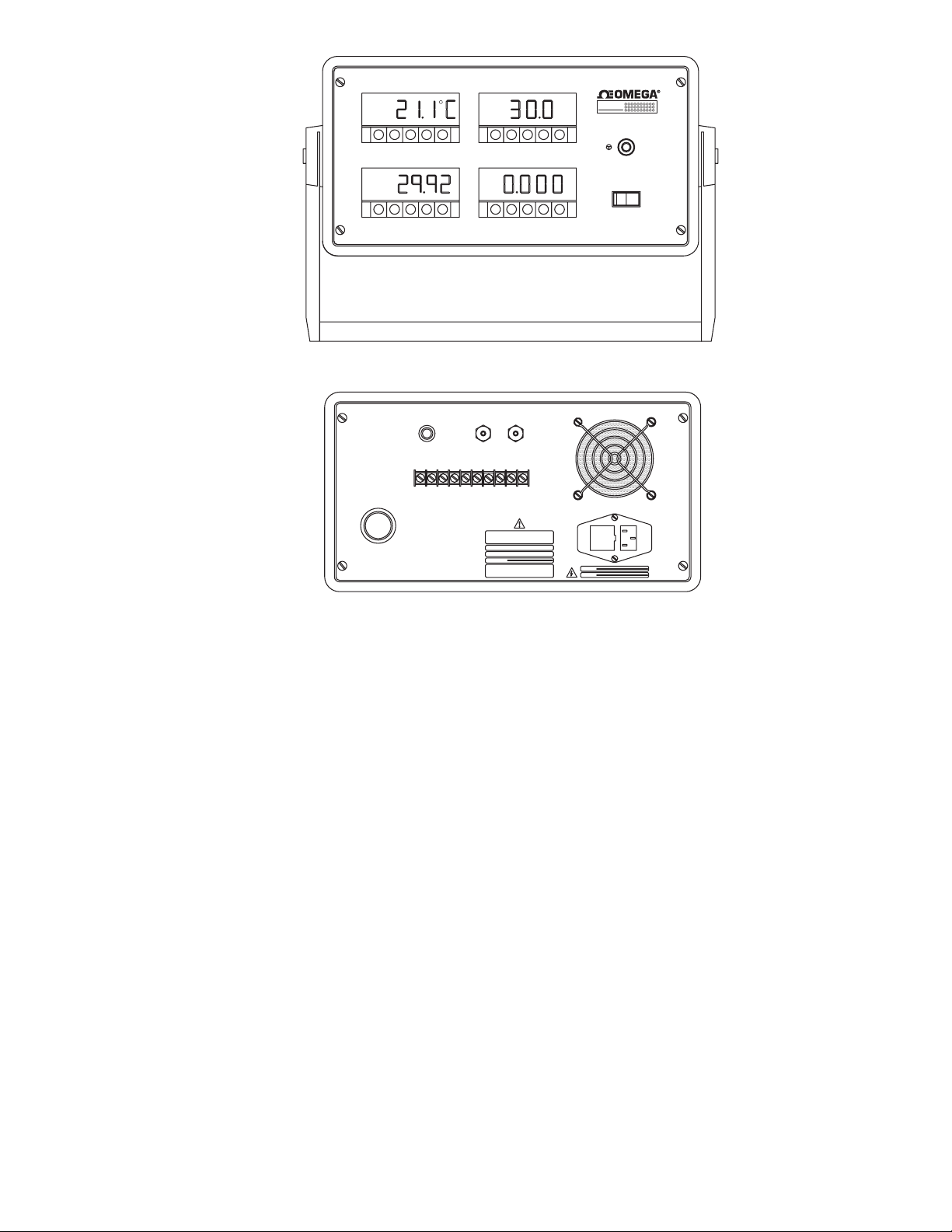
Figure 6: Standard Electronics Box; Top (Front); Bottom (Rear)
The TARE button on the front of the electronics box is used to zero out the meter.
The ON/OFF power button is to its right.
The REC connector is used to hook up any device with 10 V dc analog output. As shown in the bot tom gure,
the power cord receptacle is rated for a 115 V ac power cord.
8 Benchtop Wind Tunnel
Page 9
/
TARE
SETPTS /MIN/MAX MENU RESET
REC
+–
HIGH LOW
115 VAC
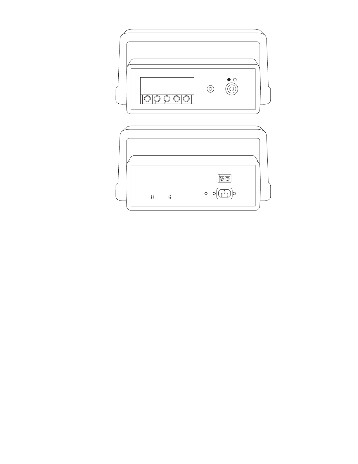
Figure 7: Deluxe Electronics Box Top (Front); Bottom (Rear)
The TARE button on the front of the electronics box is used to zero out the Differential Pressure meter only.
The ON/OFF power button is below it.
The bottom terminal strip labeled TEMP/RH/BAR/DP is used to hook up any device with 10 V dc analog
output. As shown in the bottom gure, the power cord receptacle is rated for a 115 V ac power cord.
9Setting Up the Wind Tunnel
Page 10
3. Installing the Wind Tunnel
Follow the instructions below to install the wind tunnel.
Step 1: After unpacking the box, place the wind tunnel on a level table top. Refer to Section 2 on how to select
the correct size room and how to orient the wind tunnel correctly in the room.
Step 2: Set up the motor controller. To do this, examine that the ON/OFF switch on the controller box is in the
OFF position and be certain that the potentiometer is fully counter-clockwise. Connect the two elongated
connectors together to hook up the motor and plug the motor controller into a live 120 V ac outlet. DO
NOT TURN ON THE CONTROLLER.
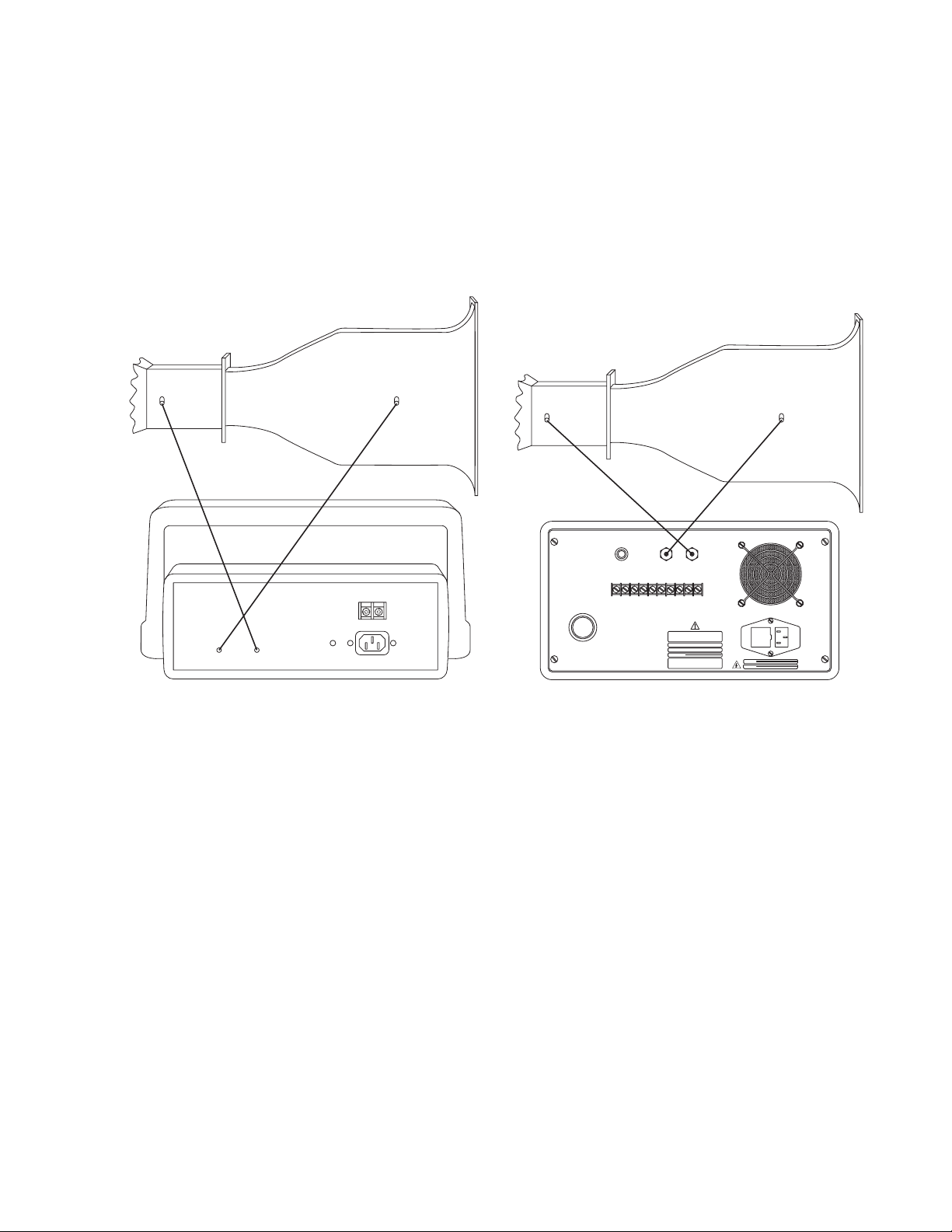
Step 3: Place the electronics box next to the tunnel. Attach the two (2) pieces of tubing as shown in Figure 8. Also
attach the power cord to the rear of the box. DO NOT TURN ON THE ELECTRONICS BOX YET EITHER.
LOW
HIGH
LOW
TEMP RH BAR DP
REC
+–
HIGH LOW
115 VAC
Figure 8: (Left) Tubing Placement with Standard Electronics Box and Wind Tunnel
(Right) Tubing Placement with Deluxe Electronics Box and Wind Tunnel
HIGH
CAUTION: FOR CONTINUED PROTECTION AGAINST
THE RISK OF FIRE REPLACE WITH ONLY THE SAME
TYPE, RATING AND SIZE OF FUSE. DISCONNECT
POWER FROM SOURCE BEFORE CHANGING FUSE.
MODEL NO:
SERIAL NO:
OMEGA ENGINEERING INC.
STAMFORD, CT. 06907-0047
1-800-826-6342
LOW
MADE IN THE U.S.A.
WT4401-D
www.omega.com
HIGH
POWER:
FUSE:
10 Benchtop Wind Tunnel
Page 11
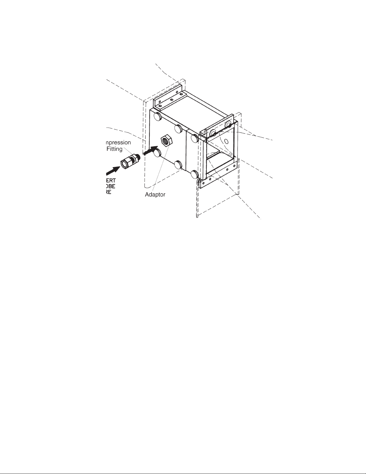
Step 4: Using the compressing ttings provided, mount the probe to be calibrated in the wind tunnel. Refer to
Figure 9. Some probes have directional air ow for upstream and downstream sides. Make sure the probe
is installed without any leaks.
Step 5: Continue to Section 4 Operating Instructions.
Figure 9: Probe Placement
11Installing the Wind Tunnel
Page 12
4. Operating Instructions
SAMPLE
Important
Always keep your original calibration reports in good, clean condition for future copying. Make duplicate copies of
the calibration reports you desire.
The differential pressures recorded in column 2 are at lab conditions (∆Ps). Standard conditions are at 21.1 °C
(70 °F) and 29.92 in Hg. Since your test will not be at the same conditions you need to calculate what the actual
differential pressures (∆Pa) will be during your operating conditions. A correction factor for air density (K) needs to
be determined. Differential pressures at standard conditions are listed in Appendix A.
Step 1: Supplied with the wind tunnel are Calibration Report sheets. Your wind tunnel can be used in different
applications: with no Restrictive Plate, with Restrictive Plate A or with Restrictive Plate B. Each pair of
sheets for each plate style is further broken down to two different units of measure - feet per minute and
meters per second. Examine the differences between the sheets and obtain the applicable Calibration
Report sheet for your application and photocopy it.
Step 2: Fill in the ambient barometric pressure and ambient temperature in the space provided on the Calibration
Report. Using the “K” formula on the sheets and a calculator, gure out the K factor. Take each value in
column 2 and multiply it by K and write the values in column 3.
Column 3 is the differential pressures that will correspond to the given ow rates in column 1. The values in
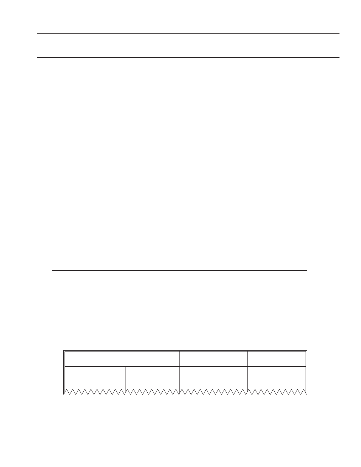
column 3 will be used in the wind tunnel setup. The top part of a calibration report is shown on the next page. If
you do not have a barometer, refer to Appendix B.
Step 3: Turn on the electronics box. If you need to zero the display, press the TARE button (on the Deluxe
Electronics Box the only display that is zeroed is the Differential Pressure display).
Step 4: Turn on the motor by ipping on the ON/OFF switch and turning the potentiometer slowly clockwise and
increase the motor speed until the actual differential pressure in column 3 is achieved.
At high speed, you will notice that the differential display tends to jump around a little which makes it tough to get
the exact same ∆P as indicated in column 3. Refer to Appendix A for this effect.
Step 5: Record the velocity from the air probe under calibration in column 4.
Step 6: Continue increasing the ow rates until you have covered the complete range you wish to calibrate.
CALIBRATION REPORT
Report Number:
Serial Number:
Model Number:
Range:
Date Calibrated:
Due Date:
STANDARD
VELOCITY (FPM)
column 1 column 3 column 4
Correction Factor: K= (29.92/P) X (460+T)/530 = _________
Where Tested Atmospheric Conditions:
P= Barometric Pressure = _____________(in Hg)
T= Atm Pressure = ___________________(F)
NO RESTRICTIVE PLATES
ACTUAL = Ps(K) UNIT UNDER
(mmHg) Pa( mmHg)
P
S
column 2
TEST
Figure 10: Calibration Report
12 Benchtop Wind Tunnel
Page 13

5. Calibrating at Other Flow Rates Not Listed in the Calibration Sheets
⎣
⎦
2
P
1
To determine the ∆P that corresponds to the desired ow rate use the following formula:
⎡
⎤
V
P2=P
where: P1 is the delta P corresponding to velocity 1
P2 is the delta P corresponding to velocity 2
V1 is a known velocity from the Calibration tables
V2 is a desired velocity not listed in the Calibration tables
Sometimes a given delta P is observed and you would like to know what ow rate it corresponds to (use the
following formula):
2
1
⎢
⎥
V
1
V2=V
1
P
where: P1 is the known actual delta P from column 4 in tables
P2 is the measured ∆P
V1 is the velocity from the tables corresponding to ∆P
V2 is the velocity that corresponds to ∆P
2
2
1
13Calibrating at Other Flow Rates Not Listed in the Calibration Sheets
Page 14
6. Specifications
Wind Tunnel
Accuracy: 1 % reading (2 % rdg with restrictive plates)
Flow Rates: 0.15 m/s to 45 m/s (25 f/m to 9000 f/m)
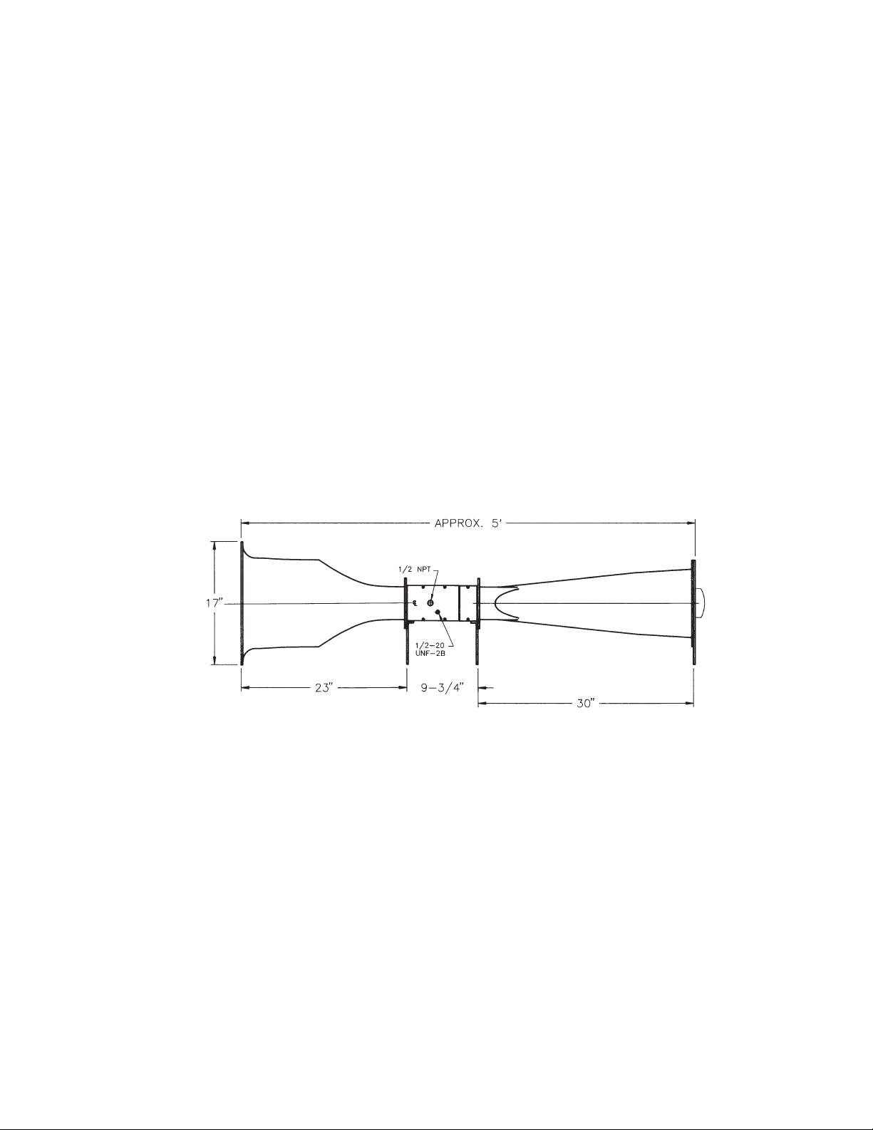
Dimensions: Refer to Figure 6-1
Weight
Wind Tunnel: 22.45 kg (49.5 lb)
Standard Electronics: 3.18 kg (7 lb)
Deluxe Electronics: 6.94 kg (15.3 lb)
Restrictive Plates A & B
Material: Clear acrylic
Overall Size (H x W): 109.2 mm x 99.1 mm (4.3 in x 3.9 in)
Size of Holes (I.D.)
Restrictive Plate A: 10.97 mm (0.432 in)
Restrictive Plate B: 6.35 mm (0.250 in)
Motor
Power: 120 V ac
Current: 12 A
Speed: 10,000 rpm
Motor Controller
Power: 120 V ac
Speed Adj: 10-turn potentiometer
Internal Adj: min, max, acceleration and current limit
Size (W x L x H): 140 mm x 184 mm x 89 mm (5.53 in x 7.25 in x 3.5 in)
Weight: 666 g (23.5 oz)
Figure 11: Dimensions
14 Benchtop Wind Tunnel
Page 15

7. In Case of Problems
Scraping noise from area of fan Realign position of the fan
The wind tunnel is not on -no power to motor
The wind tunnel is not on -fan does not turn
Can’t get velocity desired
Poor repeatability
Poor accuracy
No readings from any of the readouts
Incorrect readings from any of the readouts
Problem Solution
• Be sure the motor control-motor connector pieces
are connected to each other.
• Make sure the motor controller is plugged in and
connected to a live outlet.
• Check the fuse in the motor controller - if blown,
replace with same type and rating.
• Make sure the motor controller is plugged in and
connected to a live outlet.
• Make sure the cabling from the motor controller is
connected to the motor.
• Make sure the ON/OFF switch on the motor
controller is “ON”.
• If the switch on the motor controller is on, turn the
10-turn potentiometer clockwise from the “OFF”
position.
• Make sure there are no obstructions in the fan
area of the wind tunnel.
• Check your AC power.
• Check the position of the ON/OFF switch and
potentiometer on the motor controller.
• Make sure the appropriate restrictive plate is
used in the wind tunnel - see Section 2 for the
appropriate style to use.
• Make sure the gasket around the restrictive plate
is in good condition. If not, replace the gasket.
• Clean restrictive plate if necessary. See Section 8
for details.
• Examine all hoses for any leaks and replace any
if necessary.
• Locate the wind tunnel in room that has AT LEAST
50.97 cubic meters (1800 cubic feet) of space.
Determine if the pressure transducer is operating
correctly. If it is and there still is the accuracy
problem, return the wind tunnel to the factory and get
it recalibrated.
Check the operation of the individual meters. Consult
the appropriate operator’s manuals provided for
details.
Check the operation of the individual meters. Consult
the appropriate operator’s manuals provided for
details.
8. Maintenance
The following points should be adhered to for a maintenance-free operation of the wind tunnel.
• Make sure the wind tunnel is operating in a relatively dirt-free room that is AT LEAST 50.97 cubic meters
(1,800 cubic feet).
• If the restrictive plate(s) should get dirty for any reason, they can be cleaned very easily using a mild soap or
detergent.
Caution
Do not use any solvents.
• Make sure the silicone tubing is crimp-free and provides a good seal with the compression ttings. Replace
if necessary.
15In Case of Problems
Page 16

9. Spare Parts and Replacement Parts
Description Part Number
Restrictive Plate Cover WT-0011
Restrictive Plate A WT-0012
Restrictive Plate B WT-0013
Restrictive Plate Gasket WT-0014
Honeycomb Flow Straightener WT-0022
Thumb Screw for Restrictive Plate Cover (Assembly) WT-0060
One Piece of 1.5 m (5-ft) Silicone Tubing KCC - 0132
16 Benchtop Wind Tunnel
Page 17

10. Appendix A: Differential Pressure Fluctuation Errors
P
V
P
1
1
1
1
ΔP
ΔP
Achieving the exact desired pressure measurement at high delta pressures is sometimes a tough thing to do. The
uctuations, although appearing to be large, are actually quite small. The table on the next page shows the delta
pressure corresponding to a 1 % change in air ow velocity.
The reason why a large change in differential pressure causes only a 1 % change in the standard ow rate is
because the ow rate is proportional to the square root of the ∆P. This square root relationship is shown as
follows:
V2= V
V1 + ΔV
V
1
ΔV
1+
V
The percentage change in pressure corresponding to a 1 % change in velocity is as follows:
1 + 0.012=) 1. 0201
(
2
P
1
=
⇒
P1+ ΔP
1
P
= 1 +
ΔP
P
()
2
=
V
1
1
⎛
⇒ 1+
⎜
⎝
= 1+
P
2
P
1
2
⎞
ΔV
V
⎟
⎠
= 1 +
⇒ 2.01% =
1
ΔP
P
P
1
17Appendix A: Differential Pressure Fluctuation Errors
Page 18

RESTRICTIVE PLATE B
Standard Tol. on
Press.Velocity Ps
FPM 2% Velmm Hg
Col. 1
0
25
30
40
50
60
70
80
90
100
125
150
175
200
225
250
275
300
325
350
RESTRICTIVE PLATE B
Standard Tol. on
m/s 2% Velmm Hg
Col. 1
0
0.15
0.2
0.25
0.3
0.4
0.5
0.6
0.75
1
1.25 ±0.057
Col. 2 mm Hg
0.000 ±0.000
0.023 ±0.000
0.043 ±0.001
0.070 ±0.001
0.110 ±0.002
0.175 ±0.004
0.235 ±0.005
0.288 ±0.006
0.359 ±0.007
0.459 ±0.009
0.681 ±0.014
1.001 ±0.020
1.381 ±0.028
1.867 ±0.037
2.348 ±0.047
2.875 ±0.058
3.525 ±0.071
4.354 ±0.088
5.156 ±0.104
5.837 ±0.117
Press.Velocity Ps
Col. 2 mm Hg
0 ±0.000
0.040 ±0.001
0.065 ±0.001
0.109 ±0.002
0.168
0.279 ±0.006
0.447 ±0.009
0.609 ±0.012
0.983 ±0.020
1.795 ±0.036
2.838
±0.003
TYPICAL WIND TUNNEL DATA (ENGLISH UNITS - FPM)
RESTRICTIVE PLATE A
Standard Tol. on
Velocity Ps Press.
FPM mm Hg 2% Vel
Col. 1
0
250 ±0.006
275
300
325
350
375
400
450
500
550
600
700
800
900
1250 8.399 ±0.168
(METRIC UNITS - m/s)
RESTRICTIVE PLATE A
Standard Tol. on
m/s mm Hg 2% Vel
Col. 1
1.25
1.3
1.4
1.5
1.75
2
2.25
2.5
2.75
3
3.25
3.5
4
4.5
5
5.5
6.5
Col. 2 mm Hg
0.000 ±0.000
0.318
0.388 ±0.008
0.471 ±0.009
0.561 ±0.011
0.620 ±0.012
0.699 ±0.014
0.796 ±0.015
1.007 ±0.020
1.220 ±0.024
1.522 ±0.031
1.761 ±0.035
2.534 ±0.051
3.212 ±0.064
3.900 ±0.078
5.466 ±0.1101000
Press.VelocityPs
mm HgCol. 2
0.308 ±0.006
0.333 ±0.007
0.388 ±0.008
0.457 ±0.009
0.604 ±0.012
0.764 ±0.015
0.992 ±0.020
1.176 ±0.024
1.459 ±0.029
1.707 ±0.034
2.072 ±0.041
2.488 ±0.050
3.209 ±0.064
3.834 ±0.077
5.193 ±0.104
6.005 ±0.120
9.001 ±0.180
Standard
Velocity Ps
FPM
Col. 1
0
1000 ±0.001
1500
2000
3000
4000
5000
6000
7000
8000
9000
Standard
Velocity Ps
m/s
Col. 1
7.5
10
12.5
15
20
25
30
40
45
NO PLATE
Tol. on
Press.
mm Hg 1% Vel
Col. 2 mm Hg
0.000±0.000
0.131
0.293±0.003
0.510±0.005
1.082±0.011
1.997±0.020
2.953±0.030
4.122±0.041
5.692±0.057
7.271±0.073
9.111±0.091
NO PLATE
Tol. on
Press.
mm Hg 1% Vel
Col. 2 mm Hg
0.286±0.003
0.492±0.005
0.739±0.007
1.050±0.011
1.872±0.019
2.877±0.029
3.990±0.040
7.062±0.071
8.089±0.081
18 Benchtop Wind Tunnel
Page 19

11. Appendix B: Barometric Pressure Calculations
-ALT
Barometric pressure will affect the air density which inuences the velocity readings. The deluxe electronics box
will give the barometric pressure reading directly to you. If you do not have a barometer and wish to correct for
the barometric pressure, an airport or a local weather station can provide a standard barometric reading. Please
note that the reading they give you is standardized to sea level and 21.11 °C (70 °F).
The following correction formula can be used to determine the actual pressure at your location:
Let: Actual barometric pressure = BPa
Standard barometric pressure = BPs
Altitude above sea level = ALT
Temperature in Rankine = T
Specic air constant = 53.3 ft-lbf/lbm-R
⎛
53.3 × T
BPa = BP
e
s
⎜
⎝
Example: You are 15.24 m (50 ft) above sea level; the weather station reports 755.7 mmHg (29.75 inHg), and the
temperature is 22.22 °C (72 °F).
So the equation would be:
⎛
BPa = 29.75 ⎜e
⎝
-50
53.3× 460+72
()
⎞
⎟
⎠
⎞
= 29.70" Hg
⎟
⎠
19Appendix B: Barometric Pressure Calculations
Page 20

Differential Pressures vs Airspeed at Standard Conditions of 70°F
(21.1°C) and 29.92 in Hg.
2.35829 4500 22.86
02
02
02
02
02
02
02
02
02
02
02
02
02
02
03
03
03
03
03
03
03
03
03
03
03
03
03
03
03
03
03
04
04
04
04
04
04
04
04
04
04
04
04
mmHg FPM M/S
000
0.00116 100 0.51
0.00466 200 1.02
0.01048 300 1.52
0.01863 400 2.03
0.02911 500 2.54
0.04193 600 3.05
0.05706 700 3.56
0.07453 800 4.06
0.09433 900 4.57
0.11646 1000 5.08
0.14091 1100 5.59
0.1677 1200 6.1
0.19682 1300 6.6
0.22826 1400 7.11
0.26203 1500 7.62
0.29813 1600 8.13
0.33657 1700 8.64
0.37733 1800 9.14
0.42042 1900 9.65
0.46583 2000 10.16
0.51358 2100 10.67
0.56366 2200 11.18
0.61607 2300 11.68
0.6708 2400 12.19
0.72787 2500 12.7
0.78726 2600 13.21
0.84898 2700 13.72
0.91304 2800 14.22
0.97942 2900 14.73
1.04813 3000 15.24
1.11917 3100 15.75
1.19254 3200 16.26
1.26823 3300 16.76
1.34626 3400 17.27
1.42662 3500 17.78
1.5093 3600 18.29
1.59432 3700 18.8
1.68166 3800 19.3
1.77134 3900 19.81
1.86334 4000 20.32
1.95767 4100 20.83
2.05433 4200 21.33
2.15332 4300 21.84
2.25464 4400 22.35
20 Benchtop Wind Tunnel
mmHg FPM M/S
2.46427460
2.57257470
2.68321480
2.79617490
2.91147500
3.02909510
3.14904520
3.27132530
3.39593540
3.52287550
3.65214560
3.78374570
3.91767580
4.05393590
4.19251600
4.33343610
4.47667620
4.62224630
4.77015640
4.92038650
5.07294660
5.22783670
5.38505680
5.5446 6900 35.05
5.70647700
5.87068710
6.03722720
6.20608730
6.37728740
6.5508 7500 38.1
6.72665760
6.90483770
7.08535780
7.26819790
7.45335800
7.64085810
7.83068820
8.02284830
8.21732840
8.41414850
8.61328860
8.81476870
9.01856880
9.22469890
9.43315900
3.37
3.87
4.38
4.89
5.4
5.91
6.41
6.92
7.43
7.94
8.45
8.95
9.46
9.97
0.48
0.99
1.49
2.00
2.51
3.02
3.53
4.03
4.54
5.56
6.07
6.57
7.08
7.59
8.61
9.11
9.62
0.13
0.64
1.15
1.65
2.16
2.67
3.18
3.69
4.19
4.7
5.21
5.72
Page 21

WARRANTY/DISCLAIMER
OMEGA ENGINEERING, INC. warrants this unit to be free of defects in materials and workmanship for a period
of 13 months from date of purchase. OMEGA’s WARRANTY adds an additional one (1) month grace period to
the normal one (1) year product warranty to cover handling and shipping time. This ensures that OMEGA’s
customers receive maximum coverage on each product.
If the unit malfunctions, it must be returned to the factory for evaluation. OMEGA’s Customer Service
Department will issue an Authorized Return (AR) number immediately upon phone or written request.
Upon examination by OMEGA, if the unit is found to be defective, it will be repaired or replaced at no charge.
OMEGA’s WARRANTY does not apply to defects resulting from any action of the purchaser, including but
not limited to mishandling, improper interfacing, operation outside of design limits, improper repair, or
unauthorized modification. This WARRANTY is VOID if the unit shows evidence of having been tampered
with or shows evidence of having been damaged as a result of excessive corrosion; or current, heat,
moisture or vibration; improper specification; misapplication; misuse or other operating conditions outside
of OMEGA’s control. Components in which wear is not warranted, include but are not limited to contact
points, fuses, and triacs.
OMEGA is pleased to offer suggestions on the use of its various products. However, OMEGA neither assumes
responsibility for any omissions or errors nor assumes liability for any damages that result from the use of its
products in accordance with information provided by OMEGA, either verbal or written. OMEGA warrants only
that the parts manufactured by the company will be as specified and free of defects. OMEGA MAKES NO OTHER
WARRANTIES OR REPRESENTATIONS OF ANY KIND WHATSOEVER, EXPRESSED OR IMPLIED, EXCEPT THAT OF
TITLE, AND ALL IMPLIED WARRANTIES INCLUDING ANY WARRANTY OF MERCHANTABILITY AND FITNESS FOR
A PARTICULAR PURPOSE ARE HEREBY DISCLAIMED. LIMITATION OF LIABILITY: The remedies of purchaser set
forth herein are exclusive, and the total liability of OMEGA with respect to this order, whether based on contract,
warranty, negligence, indemnification, strict liability or otherwise, shall not exceed the purchase price of the
component upon which liability is based. In no event shall OMEGA be liable for consequential, incidental or
special damages.
CONDITIONS: Equipment sold by OMEGA is not intended to be used, nor shall it be used: (1) as a “Basic
Component” under 10 CFR 21 (NRC), used in or with any nuclear installation or activity; or (2) in medical
applications or used on humans. Should any Product(s) be used in or with any nuclear installation or activity,
medical application, used on humans, or misused in any way, OMEGA assumes no responsibility as set
forth in our basic WARRANTY/DISCLAIMER language, and, additionally, purchaser will indemnify OMEGA
and hold OMEGA harmless from any liability or damage whatsoever arising out of the use of the Product(s)
in such a manner.
RETURN REQUESTS/INQUIRIES
Direct all warranty and repair requests/inquiries to the OMEGA Customer Service Department. BEFORE
RETURNING ANY PRODUCT(S) TO OMEGA, PURCHASER MUST OBTAIN AN AUTHORIZED RETURN (AR)
NUMBER FROM OMEGA’S CUSTOMER SERVICE DEPARTMENT (IN ORDER TO AVOID PROCESSING
DELAYS). The assigned AR number should then be marked on the outside of the return package and on any
correspondence.
The purchaser is responsible for shipping charges, freight, insurance and proper packaging to prevent
breakage in transit.
FOR WARRANTY RETURNS, please have the
following information available BEFORE contacting
OMEGA:
1. Purchase Order number under which the product
was PURCHASED,
2. Model and serial number of the product under
warranty, and
3. Repair instructions and/or specific problems
FOR NON-WARRANTY REPAIRS,
for current repair charges. Have the following
information available BEFORE contacting OMEGA:
1. Purchase Order number to cover the COST
of the repair,
2. Model and serial number of the product, and
3. Repair instructions and/or specific problems
relative to the product.
relative to the product.
OMEGA’s policy is to make running changes, not model changes, whenever an improvement is possible. This affords our customers the latest
in technology and engineering.
OMEGA is a trademark of OMEGA ENGINEERING, INC. © Copyright OMEGA ENGINEERING, INC. All rights reserved. This document may not
be copied, photocopied, reproduced, translated, or reduced to any electronic medium or machine-readable form, in whole or in part, without
the prior written consent of OMEGA ENGINEERING, INC.
consult OMEGA
Page 22

®
UNIVERSAL
FLOW MONITORS
Improving the world, one measurement at a time.
TM
M-1776/0624
omega.com
 Loading...