

Page 1
b) Channel – This is the Wi-Fi channel on which the
WARRANTY/DISCLAIMER
access point is accepts connections. If not sure what
channel to use, simply select Auto.
c) Authentication – This is the security method which the
access point is using for connections. Choose the
desired security based on the present access point settings.
Use WPA2-PSK for the most secure
connection. No security can be used to
conserve battery power. WPA2-PSK
Enterprise is not supported
d) Passphrase – If the authentication is WPA2-PSK, then
enter a passphrase here.
• Passphrase restricted characters include “ ;
• The minimum characters that can be used for
Passphrase/WPA2 is 8, maximum is 63.
e) Default Key – This is the password if authentication is
WEP-128.
• WEP KEY can only use the following characters:
a b c d e f 0 1 2 3 4 5 6 7 8 9.
• WEP KEY must be a length of 26 characters.
f) DHCP – Check this option if the Transmitter will receive
a
Dynamic IP address from a DHCP server.
For initial configuration, it is recommended to
use DHCP for assigning IP Address to the
Transmitter. The IP address can be made
STATIC from the Virtual Coordinator after the
Transmitter starts communicating with it.
g) IP Address – Assign a STATIC IP address.
h) Netmask – Assign a subnet mask associated with the
STATIC IP address.
i) Gateway Address – This could be the IP address of
your access point or wireless router which the
Transmitter is associating with.
j) Virtual Coordinator IP – Assign the IP address of the
PC on which the VC is installed.
k) Communication Protocol – This is the protocol used
to communicate with the VC. Either TCP or UDP
protocol can be selected. UDP is default and uses less
battery power.
l) Virtual Coordinator Port – Readings from the sensor
(Transmitter) are sent to the VC using this port number.
Use the default UDP protocol and port 50002 unless
this port is already used on the VC. If TCP protocol is
used change this port number to 50006.
m) Update Period – Enter the Transmitter’s reading
transmission frequency in seconds.
n) Save and Reboot – Click
“Save Changes”. Verify the
settings and then click “Reboot”. The webpage should
say that the Transmitter is rebooted.
If your Transmitter has a display, you should now be
able to see the sensor readings on the display.
The Transmitter stays in AD-HOC mode for a
few minutes and then goes to sleep to
conserve battery. So the step to put the device
into AD-HOC mode and to configure it using a
web page needs to be done together.
Also during this time, it is recommended to set the
“Update Period” to the default (10 seconds). Once the
Transmitter and the VC are communicating properly, the
“Update Period” can be changed to the desired value.
3.6. Getting the Readings
If the PC used to configure the Transmitter is the same as the
one running the VC, then change its IP address to the STATIC
IP address set for the VC. Start a new browser and enter
http://<IP addres
s of PC running virtual coordinator>
If using a different PC, go to the PC running VC. Open up a web
browser and enter http://<IP address of virtual coordinator>
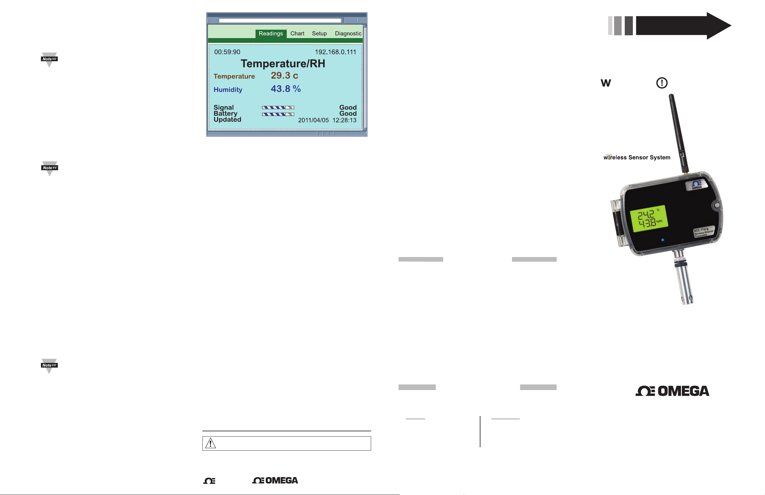
Click the button that says readings. Enter the user name as
“user” and the password as “12345678”. You should be able to
see the readings.
READINGS
http://192.168.0.105/reading_html
Figure 8
TROUBLESHOOTING
Once you apply the steps described above, if you still cannot see
the Transmitter on your VC check the following items:
1. Blue LED – The Blue LED on the Transmitter blinks every time
it transmits data. If the Blue LED is solid on it then means that
it’s trying to connect and transmit data to the access point with
no success.
2. Java Runtime Environment (JRE) – Make sure that the
Java Runtime Environment (JRE) is running on the PC on
which the VC is installed. If the Java Runtime is not installed
on the computer the VC will not display readings from the
Transmitters. Should be 32-bit Java versio
3. Wireless Connection – If you plan to connect on a wireless
LAN make sure that the wireless connection on your computer on
which the VC is installed is linked to the correct access point. You
may want to connect to the same access point to which the
Transmitter is connected. You can verify that by looking at the
Wireless Connection Manager on your computer.
4. Wired LAN – If your computer is on a wired LAN on which
the correct access point is also connected, make sure that
you can reach the access point from your computer. This
can be accompli
shed by “pinging” the IP address of the
access point.
5. Firewall – Make sure that the firewall is off or the exceptions are
added properly.
6. Back to AD-HOC Mode – If you cannot find anything wrong
with your computer wireless connection and the access point,
then there is a chance that the Transmitter was not configured
correctly. To reconfigure the Transmitter you must put the
Transmitter back into the AD-HOC mode. To do this, open the
case, slide the red Power button to the OFF position. Next, press
and hold the white Default button, slid
back to the ON position, and release the white button once the
blue LED comes up solid. You can now follow from Step 3.4 of
the Transmitter’s Initial Configuration section.
7. Access Point/Wireless Router – In general, the latest/newest
access Points are better than older ones. Also, check to see if
your access point has the latest firmware installed.
WARNING: These products are not designed for use in, and should not be used for, patient-connected applications.
This device is marked with the international caution symbol. It is important to read the
Setup Guide before installing or commissioning this device, as the guide contains important
information relating to safety and EMC.
It is the policy of OMEGA to comply with all worldwide safety and EMC/EMI regulations that apply. OMEGA is constantly
pursuing certification of its products to the European New Approach Directives. OMEGA will add the CE mark to every
appropriate device upon certification.
The information contained in this document is believed to be correct, but OMEGA Engineering, Inc. accepts no liability for
any errors it contains, and reserves the right to alter specifications without notice.
TRADEMARK NOTICE:
™
omega.com
,
™
, , are Trademarks of OMEGA ENGINEERING, INC.
n 1.6 or higher.
e the red Power switch
™
SPECIFICATION
SENSOR SPECIFICATIONS
RELATIVE HUMIDITY (wTHP, wTHP2, wBTHP)
Accuracy/Range:
±2% for 10 to 90%
±3% for 5 to 10% and 90 to 95%
±4% for 0 to 5% and
Hysteresis: ±1% RH
Non-linearity: ±3%
Repeatability: ±0.1%
Resolution: 0.1%
TEMPERATURE
Accuracy/Range*:
wTHP, wTHP2
±0.5°C for 5 to 45°C (±0.9°F for 41 to 113°F);
up to ±1.5°C for -40 to 5°C and 45 to 124°C
(up to ±2.7°F for -40 to 41°F and 113 to 255°F)
wTP1, wTP2
±0.5°C for 10 to 85°C (±0.9°F for 50 to 185°F);
±1°C for -40 to 10°C and 85 to 125°C
(±1.8°F for -40 to 50°F and 185 to 257°F)
wBTHP
±0.5°C for 5 to 45°C (±0.9°F for 41 to 113°F);
up to ±1.5°C for -40 to 5°C and 45 to 85°C
(up to ±2.7°F for -40 to 41°F and 113 to 185°F)
wBTP
±0.8°C @ 25ºC (±1.5°F @ 77ºF)
±4°C for -40 to 85°C (±7.2°F for -40 to 185ºF)
*NOTE: extended temp range is for Probe only,
the Controller’s operating temp is -10 to 55ºC
Resolution: 0.1°C
BAROMETRIC PRESSURE (wBTP, wBTHP)
Accuracy/Range:
±2 mbar for 300 to 1100 mbar @ 0 to 50ºC
±6 mbar for 300 to 1100 mbar @ -40 to 85ºC
Resolution: 0.1 mba
ANALOG VOLTAGE & CURRENT INPUT (wVI)
Voltage Input:
Differential; bipolar; ±100 mV, ±1 V, ±10 V
Input Impedance: 38 K ohm for voltage
Current Input:
Differential; bipolar; ±20 mA (5 ohm load)
Accuracy: ±0.1% Full Range @ 25ºC
Reading Rate: Periodic (1 sample/update) or
continuous (3 samples/second)
Resolution: 16 bits
OMEGA ENGINEERING, INC. warrants this unit to be free of defects in materials and workmanship for a
period of 13 months from date of purchase. OMEGA’s WARRANTY adds an additional one (1) month grace
period to the normal one (1) year product warranty to cover handling and shipping time. This ensures
that OMEGA’s customers receive maximum coverage on each product.
If the un it malfunctions, it must be returned to the f actory for e valuation. OMEGA’s Customer Service
Departmen t will issue an Aut horized Return (AR) number immediatel y upon phone or wr itten re quest.
Upon examination by OMEGA, if the unit is found to be defective, it will be repaired or replaced
charge. OMEGA’ s WARRANT Y doe s not a pply t o def ects resultin g from any action of the purchaser,
incl uding but not limited to misha ndling, imp roper interfa cing, operati on outsid e of design l imit s,
improper repair, or unauth orized modif ication. This WARRANTY i s VOID if the unit sh ows evidence of
having been tampered with or shows evidence of having been damaged as a result of excessive corrosion;
or current, heat, moisture or vibration; improper speci fication; misapplication; mis
conditions outside of OMEGA’s control. Components in which wear is not warranted, include but are not
limited to contact points, fuses, and triacs.
OME GA is ple ase d to offer suggesti ons on the use of its various products. Howeve r,
OMEGA neither ass umes responsibility for a ny omissions or error s nor assumes liability for
any damages that result from the use of its products in accordance with information provided
by OMEGA, either verbal or written. OMEGA warrants only that the parts manufactured by the
company will be as specified and free of defects. OMEGA MAKES NO OTHER WARRANTIES OR
REPRESENTATIONS OF ANY KIND WHATSOEVER, EXPRESSED OR IMPLIED, EXCEPT THAT OF
TITLE, AND ALL IMPLIED WARRANTIES INCLUDING ANY WARRANTY OF MERCHANTABILITY
AND FITNESS
LIABILITY: The remedies of purchaser set forth herein are exclusive, and the total liability of
OMEGA with res pect to this order, wheth er bas ed on contrac t, war ran ty, negli gen ce,
indemnif ication, strict liabilit y or otherwise, shall not exceed the purchase pri ce of the
co mp on en t u pon whic h l ia bi lity is base d. In no eve nt sh al l OME GA be li ab le fo r
consequential, incidental or special damages.
CONDITIONS: Equipment sold by OMEGA is not intended to be used, nor shall it be used: (1) as a “Basic
Component” under 10 CFR 21 (NRC), used in or with any nuclear installation or activity; or (2) in medical
cations or used o n humans. Should any P roduct(s) be used in or with any nuclear installation or
appli
activity, medical application, used on humans, or misused in any way, OMEGA assumes no responsibility
as set forth in our bas ic WARRANTY/DISCLAIMER language, and, add itionally, purchaser will indemnif y
OMEGA and hold OMEGA harmless from any liability or damage whatsoever arising out of the use of the
Product(s) in such a manner.
Direct all war ranty and rep air requests/inqu iries to the OMEGA Customer Service Department. BEFORE
RETURNING ANY PRODUCT(S) TO OMEGA, PURCHASER MUST OBTAIN AN AUTHORIZED RETURN (AR)
NUMBER FROM OMEGA ’S CUSTOME R SE RVICE DEPARTMENT (IN ORDER TO AVOI D PROCESSING
DELAYS). The assigned AR number should then be marked on the outside of the return package and on any
correspondence.
The purchaser is respo nsible for shipping charges, freight, insurance and proper p ackaging to prevent
breakage in transit.
FOR WARRANTY RETURNS, please have the
following information available BEFORE contacting
OMEGA:
1. Purchase Order number under which the product
was PURCHASED,
2. Model and serial number of the product under
warranty, and
3. Repair instructions and/or specific problems
relative to the product.
OMEGA’s p olicy is to make running changes, not model changes, whenever an improvement is possible. This affords our
customers the latest in technology and engineering.
OMEGA is a trademark of OMEGA ENGINEERING, INC.
© Copyright 2018 OME GA EN GINEERING , IN C. A ll ri ghts reserved . Th is d ocument may not be copied, phot ocopied,
reproduced, translated, or reduced to any electronic medium or machine-readable form, in whole or in part, without the prior
written consent of OMEGA ENGINEERING, INC.
95 to 100%
r
FOR A PARTICU LAR PURPOS E ARE H EREBY DISCLAI MED. LIMI TATI ON OF
RETURN REQUESTS/INQUIRIES
THERMOCOUPLE INPUT (wTC)
Thermocouple Type (ITS 90):
J, K, T, E, R, S, B, C, N, L
Reading Rate: Periodic (1 sample/update) or
continuous (3 samples/second)
METER SPECIFICATIONS
Supported Protocols (Transmitter): TCP/IP,
UDP, ARP, ICMP, DHCP, HTTP and FTP
Supported Protocols (VC):
TCP/IP, UDP, HTTP, FTP, SMTP and Telnet
WIRELESS COMMUNICATION
Standard: IEEE 802.11 b/g
Frequency: 2.4 GHz (2402~2483.5 MHz)
Range: 60m (200') indoor line-of-site
or more depending upon sensitivity,
data rate, wireless access point and
environmental considerations
Radio Power Output Level (Class 1):
91.4 mW EIRP (19.6 dBm EIRP)
Modulation:
802.11b compatibility: DSSS (CCK-11,
CCK-5.5, DQPSK-2, DBPSK-1);
802.11g: OFDM (de
Channels: 1 to 13; Channel 14 for Japan use
only and is not certified.
Channel Spacing (Bandwidth): 20 MHz
Transmission Rate (Over the Air):
802.11b: 1 to 11 Mbps for
802.11g: 6 to 54 Mbps
POWER (wSERIES AC POWER)
Power Input: 5 Vdc
Consumption: 0.7 W max
Safety Qualified AC Power Adapter
(included):
Nominal Output: 5 Vdc @ 0.6 A
Input: 100 to 240 Vac, 50/60 Hz
Back-up Alkaline Battery:
One AA 1.5 Vdc, supplied
POWER (wSERIES-CCELL)
Alkaline Battery: Two C-CELL 1.5 Vdc, supplied
Lifetime: Estimate of 2.4 years (wTC/wVI) and
4.3 years (wTxxP/wBxxP) with frequency of 1
reading per 1 minute
Dimensions:
96.5H x 146.3W x 50.8D mm (3.8 x 5.76 x 2"),
not including connectors or antenna
Operating Temperature:
-10 to 55ºC (14 to 131ºF), 90% RH non-condensing
AC Power Adapter: 0 to 40ºC (32 to 104ºF)
FOR NON-WARRANTY REPAIRS, consult
OMEGA for current repair charges. Have
the following information available BEFORE
contacting OMEGA:
1. Purchase Order number to cover the COST
of the repair,
2. Model and serial number of the product, and
3. Repair instructions and/or specific problems
relative to the product.
fault)
use or other operating
MQS5029/0918
at no
SETUP GUIDE
Series
Wi-Fi
802.11b/g Wireless Ethernet
Wireless
Transmitter
™
omega.com [email protected]
Servicing North America:
U.S.A. Omega Engineering, Inc.
Headquarters: Toll-Free: 1-800-826-6342 (USA & Canada only)
Customer Service: 1-800-622-2378
(USA & Canada only)
Engineering Service: 1-800-872-9436
(USA & Canada only)
Tel: (203) 359-1660 Fax: (203) 359-7700
e-mail: [email protected]
For Other Locations Visit omega.com/worldwide
Page 2
START HERE
key 1
This Quick Start Reference provides information on setting up
your instrument for basic operation. The latest wSeries manual
can be found at www.omega.com/manuals and the latest
software, including the
“Virtual Coordinator” can be found at
www.omega.com/software
BEFORE YOU BEGIN
Parts Included:
• Transmitter
• Antenna
• Batteries and/or AC adapter
• Sensor (for models with an
included digital sensor)
• CD with Virtual Coordinator
Software, check our website
for latest version.
Hardware/System Requirements:
You will need a computer, tablet, or
smart phone that has Wi-Fi
infrastructure and is Ad hoc capable.
System Requirements: Windows
XP, Vista, Windows 7 32/64-bit,
Windows Server 2008 32/64-bit,
Java 32-bit version 1.6 and above,
Processor: 1GHz, RAM: 2GB,
Browser: IE9 or Mozilla Firefox
Access Point/Wireless Connection:
You will need an Access Point /
Wireless Router.
You will need the following
information to ensure your device
works correctly:
• Wireless Access Point SSID
• Passphrase/Security Settings
• IP Address (for transmitter)
• Netmask
• Gateway Address
• IP Address of computer that
will run the “Virtual
Coordinator” service.
OVERVIEW
wSeries wireless Transmitters take readings from the attached
sensors, and transmit data on a wireless Ethernet 802.11b/g network
commonly referred to as “Wi-Fi.” These Transmitters are not
“stand-alone” devices, they transmit data to the Virtual Coordinator.
The wSeries wireless sensor system provides Web-based monitoring
of Analog Current and Voltage, Temperature, Humidity, and
Barometric Pressure.
As with all Wi-Fi devices, the wSeries “Transmitters” are assigned
unique IP addresses and connect to the LAN through a Wireless
Access Point/Router.
To conserve battery power, the Transmitters wake up, take readings,
transmit data and quickly go back to sleep. The user can select the
frequency of transmissions. Less frequent transmissions
result in
longer battery life. In applications where battery life is not an issue,
the wSeries device can transmit continuously, up to three sensor
readings per second.
The wireless transmitter mount discretely on the wall in clean rooms,
laboratories, museums, computer server rooms, warehouses, and
any remote facility.
THE VIRTUAL COORDINATOR “VC” WEB SERVER
The “Virtual Coordinator” is a data logging software application
running on a Windows or Linux computer somewhere on the
network. The “VC” logs/collects data from the wireless Transmitters.
The VC includes a Java-based Web server that can display
readings, charts, and record data sent by the transmitters.
The readings, data, and charts are viewed from a Web browser.
The browser accessing
the VC Web server, can be the same
computer on which the VC is installed-- or any other device with Web
browsing capabilities on the local network or the Internet
(a computer, tablet or smart phone).
For Windows PC’s
The VC runs as a “Service” in the background, rather than a
“Program”. As long as the computer and its network connection is
functioning correctly, the VC will collect data from the transmitters
and serve it to Web browsing clients as requested. The VC can also
provide data to popular Data Acquisition and Process Control
programs running elsewhere on the network. Meanwhile, the
computer running the VC server can be used for other tasks.
Chart scales are fully adjustable on the fly. For example, the chart
can display one minute, one hour, one day, one week, one month
or
one year. Temperature and humidity can be charted across the full
span (-40 to 125°C, and 0 to 100% RH) or within any narrow range
such as (20 to 30°C).
The OPC Server software makes it easy to integrate the wSeries
wireless sensor system with many popular Data Acquisition and
Automation programs offered by Omega, Wonderware, iConics,
Intellution, Rockwell Automation, and National Instruments,
among others.
CONFIGURATION
1. Configuring the computer running Virtual Coordinator
Software (VC)
1.1. Disable Power Safe Options:
The computer running VC software needs to be running
continuously. To do that:
a) Go to Control Panel>System and Security>Power Options.
Choose the Power Plan>Change Plan Settings>Change
Advanced Settings. Then choose the Hard Disk>Turn Off Hard
Disk Option. Reduce this number from 20 to 0 (Never).
Save the settings.
b) These settings may be different on Windows XP.
Choose the Option to Never Turn Off Hard Disks and Never Put
the System to Standby.
Figure 1
1.2. Java Runtime Environment:
This PC needs to have the latest Java Runtime Environment
(JRE) installed. First check the JRE installed.
Go to Control Panel and look for the icon named Java.
that will start the Java Control Panel. Go to the Java tab and click
on View button.
Note the Version number. It should be something like 1.6.0.x. If the
version number is anything less than 1.6 then go to www.java.com,
download and install the latest version of JRE.
1.3. Firewall Exception:
This computer may have a firewall running which will block the
readings sent from the sensor (transmitter) to the VC Software.
Configure the firewall to allow this data to go through. Refer to
Appendix K and L in Operators Manual to configure the firewall.
1.4. IP Address:
If this computer is used to run the VC only and not to configure the
Transmitter, then set a desired STATIC IP address.
If this PC is used for configuring the
Transmitter then set up a
STATIC IP address of 169.254.1.2 for AD-HOC.
It is recommended to have the computer running VC
hard-wired to the access point/wireless router.
For initial setup it is recommended to place the
Transmitter and the VC close to the wireless access
point/wireless router. Once the configuration is done the
Transmitter can be mounted to the desired location.
This configuration applies to Windows PC. For Linux, visit
our website or read the instructions in the CD.
One can also use a mobile device with a wireless (Wi-Fi)
to configure the Transmitter.
2. Installing Virtual Coordinator Software
Find the setup.exe in the accompanying CD or on the web.
Double click that to install it.
The setup process is typical to any Windows program and asks you
to choose the
installation path and whether it is a new installation or
an upgrade You must have the Administration Rights to the PC
when installing the VC.
Now go to Start>All Programs>Newport>Virtual Coordinator
Manager. Click on Install Services twice and wait until it prompts
you to reboot the PC. Reboot the PC to start all the services of
Virtual Coordinator. Once the PC reboots, open up a web browser
like Internet Explorer, type in your PC’s IP Address and a Virtual
Coordinator web page should show up. This means that the Virtual
Coordinator web-server is running.
Clicking
White
Default
Push Button
Switch
Red Power
Slide Switch
OFF
ON
Main Bd
SW2
Sensor Connector
(M12 shown)
of Transmitter
SW1
Inside view
Battery or
Power Board
Antenna
AC Adapter
(If ordered)
Transmit
Blue LED*
* If you have
an LCD option,
the Blue LED
will be on the
LCD board.
Figure 2
3. Configuring the Transmitters
Attach the antenna.
3.1. Connecting Sensors
Connect the sensors: digital probes, thermocouples, or analog inputs.
The digital probes for temperature, humidity, and barometric
pressure use a NEMA 4, IP65 M12 connector.
Thermocouple wires and analog voltage & current wires thread
through the NEMA 4, IP65 cable gland to the J1 terminals as
shown in Figure 3.
GNDI-I+
V-
321
V+
WIRE
ENTRY
J1
WIRE
ENTRY
-+GND
65432
CH 2
GND-+
1
CH 1
Thermocouple
Option Board,
inside case
I-I+V-
987
J1
CH 1 CH 2
V+
654
Voltage/Current
Option Board,
inside case
wTC units wVI units
Figure 3
3.2. Battery Installation
Install batteries or connect the AC adapter (depending on model),
you will need to open the transmitter’s cover, refer to Figure 2.
3.3. There are two ways for set-up: 1) Using Transmitter’s Factory
Default Settings. 2) AD-HOC mode. Refer to main operators
manual for Default Set-Up instructions.
3.4. Powering ON the Transmitter
IMPORTANT
The first time you power on the
follow this sequence or risk corrupting the firmware. If the
firmware gets corrupted, the unit must be returned to the
factory to have the firmware reinstalled.
6.1. Make sure the red power switch is OFF.
See diagram in Figure 2.
6.2. Install two C-cell batteries, or connect AC adapter
and install backup AA battery.
6.3. Press and hold white reset button (labeled "SW2").
6.4a. While continuing to press the white reset button,
slide the red power switch ("SW1") to ON.
6.4b. Do not release the white reset button until the blue
LED comes on solid (not blinking).
6.5. The transmitter is now in AD-HOC mode for initial
wireless configuration.
3.5. AD-HOC Mode using a Windows PC or iOS (iPhone/iPad)
You can use a PC
or an iOS device to configure your Transmitter.
While in AD-HOC mode, Transmitters with an LCD display will show
the last 4 characters of its Mac address (part of SSID) on the display.
transmitter, you must
Figure 4
3.6 Finding the Transmitter
For the AD-HOC to synch with
the PC it usually takes 2-3
minutes after the Transmitter is
powered ON. For iOS Devices
it is much quicker, a few
seconds. Check the Wireless
Network on the PC or Wireless
Settings/Wi-Fi on the iOS
device that is used to configure
the Transmitter.
This configuration software for
wireless networks will show a
network TXABCD (ABCD are
the last four characters in the
MAC address of the Transmitter).
Currently connected to:
Home
Local and Internet access
Wireless Network Connection
TX5990
Connected
DLink655
Linksys2100e
Lab1
Lab2
Open Network and Sharing Center
Figure 5 - Windows PC
Wi-Fi Settings
The Transmitter which is in
AD-HOC mode is running this
wireless network.
Connect to this network by
double clicking it. Once
connected it should show the
status CONNECTED.
Start up a web browser and
type in the IP address of
http://169.254.1.1 and you
should see a webpage for Initial
Configuration. Enter
here. Refer to Figure 7
the settings
Figure 6 - iPhone
Wi-Fi Settings
Initial Configuration
Firmware Version:: “X.XX”
802.11 Configuration
Access Point SSID
Channel
Authentication
Passphrase
Default Key
Key 1
Key 2
Key 3
Key 4
TCP/IP Network Configuration
DHCP
MAC Address
IP Address
Netmask
Gateway Address
Virtual Coordinator
Virtual Coordinator IP
Communication Protocol
Virtual Coordinator Port
Transmitter
Update Period
Mode (UDP Only)
Save Changes Reset
Reboot device with saved settings and go to run mode.
After click on the Reboot button, please wait few seconds
and check with Virtual coordinator
Auto
WPA2-PSK
00:03:34:00:59:90
169.254.1.1
255.255.0.0
0.0.0.0
192.168.0.0
UDP
50002
10
seconds
Power save Enabled
Reboot
Figure 7 - Screen of Windows PC or iOS Device
3.7. This is the only page in the Transmitter’s Web server designed
for important parameters needed to initially configure the Transmitter.
Later, you will have a chance to make changes in the Transmitter
through the VC if needed.
a) Access Point SSID – This is the name that the access
point/wireless router is broadcasting on your Wi-Fi
wireless network. In order for the Transmitter to associate
itself with the access point, enter the access point’s SSID.
• SSID restricted characters include ? “ $ [ ] \ + ;
• SSID cannot begin with ! or #.
• The length of SSID is 1 to 32 characters.
 Loading...