

Page 1
WPR2 SERIES
Installation & Operation Instructions
GENERAL INFORMATION
The ACI WPR2 Series Remote Wet to Wet
Dierential Pressure Transmitter is designed to
reduce installation time and provide mounting
exibility, often eliminating the need for
additional plumbing and manifolds. The WPR2
can be ordered with standard CMP rated PVC
cable or with a metal clad cable. The metal clad
cable provides end to end protection of the
cables with exible metal conduit, durable and
resistant 304 stainless steel construction. The
WPR2 accurately measure wet media pressures
in a variety of applications. Commonly used
for monitoring pumps, these devices are also
ideal for measuring pressure across lters, heat
exchangers and compressors. The dual remote
sensors are based on a ceramic capacitive
sensing element with ¼”-18 NPT male (304
stainless steel) ttings. The WPR2’s enclosure
opens conveniently to allow it to be recongured
between three additional ranges and outputs of
4 to 20 mA , 0 to 5 VDC, or 0 to 10 VDC (default).
The dierent congurations in this series can
measure both uni or bi-directional pressure
ranges as low as 3 psi and as high as 300 psi,
depending on the unit.
Phone: 1-888-967-5224
Website: workaci.com
Precautions:
• Do not switch pressure range and output
mode when power is on. Make sure
to power o the unit rst, then move
jumpers to the correct positions and
then power on the transmitter.
• Do not apply any external voltage to
zero terminals.
• Do not replace pressure sensors with any
other sensors. Do not interchange the
high and low sensors. The high and low
sensors are specically calibrated to the
WPR2 unit.
Any changes to the sensors will void the
product warranty
MOUNTING INSTRUCTIONS
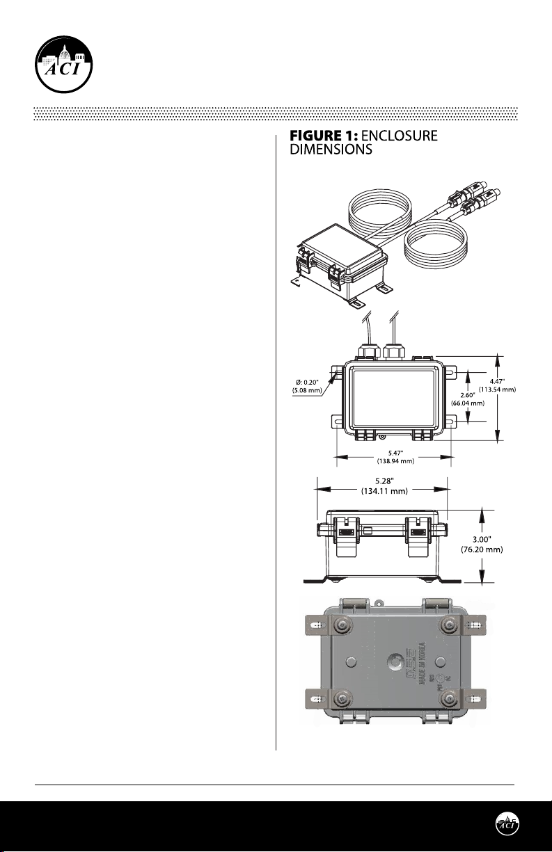
The WPR2 is supplied with 4 mounting anges.
The mounting anges must be installed onto
the bottom of the enclosure. Align the mounting
anges with the threaded insert on the bottom
of the enclosure. Insert and tighten down the
screws.
Automation Components, Inc.
2305 Pleasant View Road | Middleton, WI 53562
Phone: 1-888-967-5224 | Website: workaci.com
Page 1
Version: 22.0
I0000756
Page 2
Find a suitable location for the enclosure. Drill pilot holes for the (4) mounting screws. Use the enclosure
ange as a guide, or use the dimensions listed in FIGURE 1 (p. 1) to measure out.
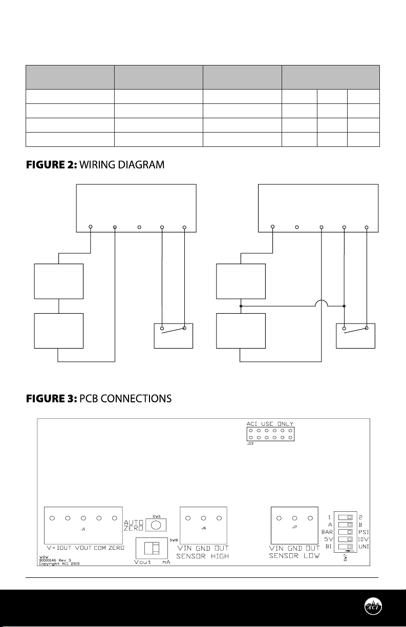
Output Signal
(SW8)
Output Mode
(SW7 Position 2)
Supply Voltage Wire Connection
Vout 0-5 VDC (5V) VAC/VDC V+ COM VOUT
Vout 0-10 VDC (10V) VAC/VDC V+ COM VOUT
mA 4-20 mA VDC V+ ----- IOUT
mA 4-20mA VAC V+ COM IOUT
Current Output Voltage Output
WPR2 Terminals
V+
IOUT VOUT
COM
ZERO
WPR2 Terminals
V+
IOUT VOUT
COM
+
VDC
Power Supply
Com
Com
Current
Meter
+
Relay
+
VDC/VAC
Power Supply
Com
Com
Voltage
Meter
+
Relay
ZERO
Automation Components, Inc.
2305 Pleasant View Road | Middleton, WI 53562
Phone: 1-888-967-5224 | Website: workaci.com
Page 2
5
4
3
2
1
ON
Version: 22.0
I0000756
Page 3
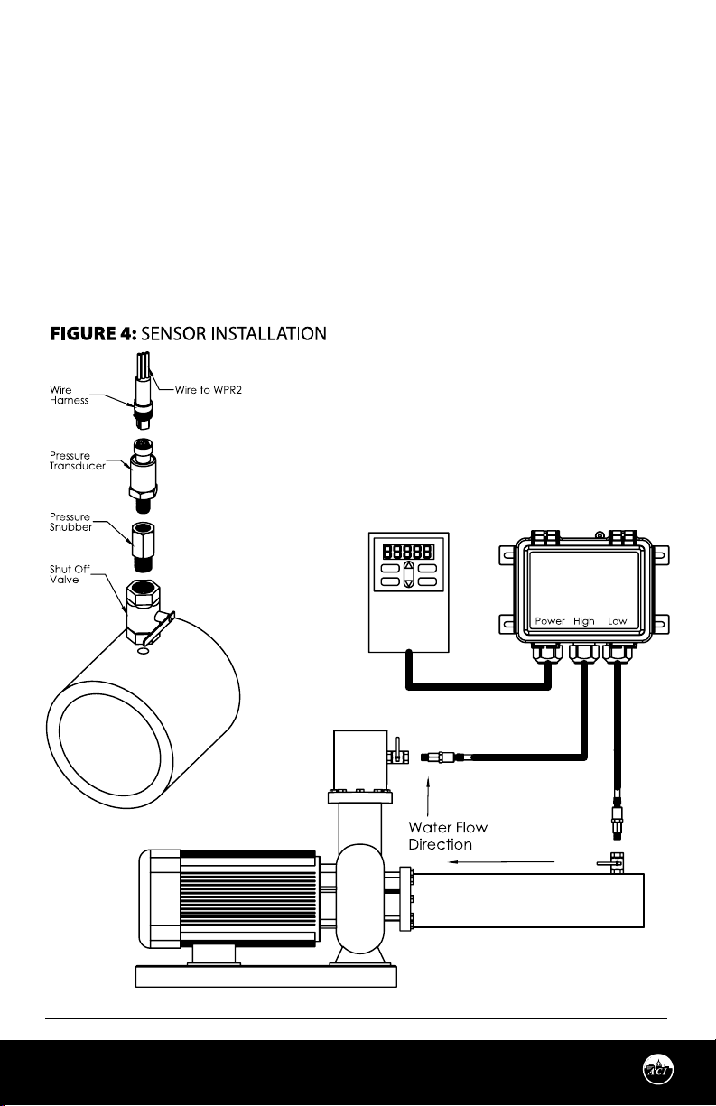
WIRING INSTRUCTIONS
PRECAUTIONS
• Remove power before wiring. Never connect or disconnect wiring with power applied.
• When using a shielded cable, ground the shield only at the controller end. Grounding both
ends can cause a ground loop.
• It is recommended you use an isolated UL-listed class 2 transformer when powering the unit
with 24 VAC. Failure to wire the devices with the correct polarity when sharing transformers
may result in damage to any device powered by the shared transformer.
• If the 24 VDC or 24VAC power is shared with devices that have coils such as relays, solenoids,
or other inductors, each coil must have an MOV, DC/AC Transorb, Transient Voltage
Suppressor (ACI Part: 142583), or diode placed across the coil or inductor. The cathode, or
banded side of the DC Transorb or diode, connects to the positive side of the power supply.
Without these snubbers, coils produce very large voltage spikes when de-energizing that
can cause malfunction or destruction of electronic circuits.
Open the cover of the enclosure. ACI recommends
16 to 26 AWG twisted pair wires or shielded cable
for all transmitters. Twisted pair may be used for
2-wire current output transmitters or 3-wire for
voltage output. All wiring must comply with local
and National Electric Codes. After wiring, close the
cover.
WPR2
Automation Components, Inc.
2305 Pleasant View Road | Middleton, WI 53562
Phone: 1-888-967-5224 | Website: workaci.com
VFD
Page 3
Version: 22.0
I0000756
Page 4

Each WPR2 unit can be configured to three output modes: 4-20mA, 0-5V and 0-10V. Use the Wiring
Connections table to determine the proper wiring for your application. See TABLE 1 for Output Mode
and Output Signal switch positions.
Note: The WPR2 units are shipped from the factory set up with a 0-10 VDC output.
ZERO FUNCTION
The WPR2 unit should be “ZEROED” before pressure transducers are installed on the pipes. The Auto zero
button and remote zero are both used to cancel out the offsets caused by installation and sensor drift.
Note: Make sure a minimum of 10 minutes of warm-up time elapse before adjustment to the ZERO. The
Zero adjustment must be performed with NO pressure applied to both sensors.
Directions:
• Shut off your main pressure valve and open a shutoff valve with hose drain to equalize the
pressure in the line to your atmosphere.
• Remove the sensors from the system to remove pressure from each sensor to achieve equal
pressure.
• Push “ZERO” button or “SHORT ZERO PIN” for 2 seconds to “COM PIN” before installation or
when it is necessary.
For units with LCD display, “ZERO” icon will be on when the unit enters zero mode. If zeroing process is
successful, the “ZERO” icon will flash twice.
• Reapply the pipe tape, thread sealant, or pipe compound before sensor installation.
PRESSURE CONNECTIONS
The WPR2 Series have 1/4”-18NPT male ttings. The sensors are labeled “SENSOR HIGH” and “SENSOR
LOW”. Make sure the sensors are wired to the corresponding terminal block inside the housing.
Otherwise, ACI will not guarantee the accuracy specications. DO NOT REPLACE SENSORS WITH ANY
OTHER SENSORS. THE WPR2 UNITS ARE CALIBRATED WITH THE HIGH AND LOW SENSORS SUPPLIED
WITH THE UNIT. Standard pipe ttings and installation procedures should be used during installation.
Install pipe tape, thread sealant or other suitable pipe compound when connecting the sensor to the
pressure source or any of the accessories. Recommended torque specication is 150 in lbs (16.95 Nm).
If after connecting the pipe, the unit outputs out-of-range signal OVR on display only, turn o the unit,
disconnect the pipe or shut down the valves immediately and check the pressure input with a gauge or
other test instrument.
Note: ACI recommends to mount the pressure transducers on the top side of the pipe. Side mounts are
also acceptable. Refrain from mounting underneath the pipes so that any moisture, sediments, or other
contaminants cannot run down or drip directly onto the sensor.
A Pressure Snubber is included with each sensor to dampen pressure surges. A pigtail siphon should be
used to lower the media temperature below 257°F (125°C) to prevent damage to the pressure sensor.
INPUT RANGE ADJUSTMENT
• Do not switch pressure range and output mode when power is on. Make sure power to the unit is
o. Failure to do so will not allow any new switch settings to take place.
• Choose dierential range based on the expected dierential pressure in your application. Move
switches to the correct positions and then power on the transmitter.
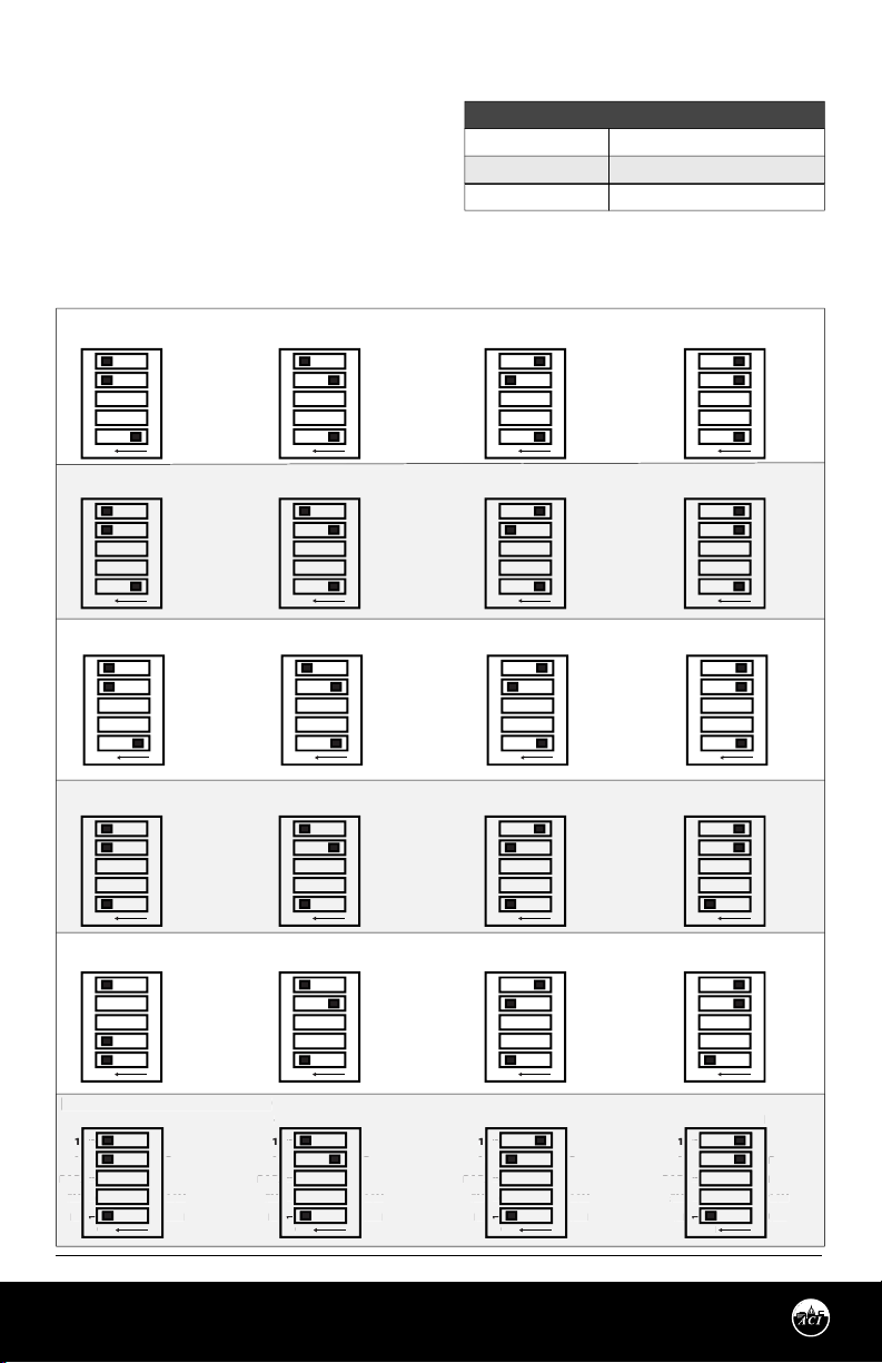
The WPR2 can operate in either unidirectional mode (0 – X PSI) or bidirectional mode (± X PSI). The unit
will be set at unidirectional mode after factory calibration. Refer to TABLE 2 (p. 5) and FIGURE 5 (p. 5).
Page 4
Automation Components, Inc.
2305 Pleasant View Road | Middleton, WI 53562
Phone: 1-888-967-5224 | Website: workaci.com
Version: 22.0
I0000756
Page 5
Unidirectional Mode
FIGURE 5: SWITCH SETTINGS
-300 to 300 PSI
0
ON
B
5V
B
UNI
0V
SI
B
ON
B
5V
B
UNI
0V
SI
B
ON
B
5V
B
UNI
0V
SI
B
ON
B
5V
B
UNI
0V
SI
B
SI
SI
-30 to 30 PSI
• DIP switch SW7 position 1 set at UNI side.
• DIP switch SW7 positions 4 and 5 are for
Range Selection
Bidirectional Mode
• DIP switch SW7 position 1 set at BI side.
• DIP switch SW7 positions 4 and 5 are for
Range Selection.
[UNIDIRECTIONAL] WPR2-30
0 to 30 PSI
1
A
BAR
5V
12345
BI
ON
[UNIDIRECTIONAL] WPR2-100
0 to 100 PSI
1
A
BAR
5V
12345
BI
ON
[UNIDIRECTIONAL] WPR2-300
0 to 300 PSI 0 to 150 PSI 0 to 75 PSI 0 to 30 PSI
1
A
BAR
5V
12345
BI
ON
[BIDIRECTIONAL] WPR2-30
-30 to 30 PSI
1
A
BAR
5V
12345
BI
ON
[BIDIRECTIONAL] WPR2-100
-100 to 100 PSI
1
A
BAR
5V
12345
BI
ON
[BIDIRECTIONAL] WPR2-300
[BIDIRECTIONAL] WPR2-30
-300 to 300 PSI
1
A
BAR
AR
5V
12345
I
BI
ON
2
B
PSI
10V
UNI
2
B
PSI
10V
UNI
2
B
PSI
10V
UNI
2
B
PSI
10V
UNI
2
B
PSI
10V
UNI
2
B
PSI
P
10V
1
UNI
0 to 15 PSI
1
A
BAR
5V
12345
BI
0 to 50 PSI
1
A
BAR
5V
12345
BI
1
A
BAR
5V
BI
-15 to 15 PSI
1
A
BAR
5V
12345
BI
-50 to 50 PSI
1
A
BAR
5V
12345
BI
-150 to 150 PSI -75 to 75 PSI -30 to 30 PSI
-150 to 150 P
1
A
BAR
AR
5V
12345
I
BI
TABLE 2: MAXIMUM PRESSURE
ACI Part #
WPR2-30
WPR2-100
WPR2-300
0 to 7.5 PSI
2
B
PSI
10V
ON
ON
12345
ON
ON
ON
UNI
2
B
PSI
10V
UNI
2
B
PSI
10V
ON
UNI
2
B
PSI
10V
UNI
2
B
PSI
10V
UNI
2
B
PSI
P
10V
1
UNI
1
A
BAR
5V
12345
BI
ON
0 to 25 PSI
1
A
BAR
5V
12345
BI
ON
1
A
BAR
5V
12345
BI
ON
-7.5 to 7.5 PSI
1
A
BAR
5V
12345
BI
ON
-25 to 25 PSI
1
A
BAR
5V
12345
BI
ON
-75 to 75 P
1
A
BAR
AR
5V
12345
I
BI
ON
Maximum Pressure (PSI)
30
100
300
2
B
PSI
10V
UNI
2
B
PSI
10V
UNI
2
B
PSI
10V
UNI
2
B
PSI
10V
UNI
2
B
PSI
10V
UNI
2
B
PSI
P
10V
1
UNI
1
A
BAR
5V
BI
0 to 10 PSI
1
A
BAR
5V
BI
1
A
BAR
5V
BI
1
A
BAR
5V
BI
-10 to 10 PSI
1
A
BAR
5V
BI
1
A
BAR
AR
5V
I
BI
0 to 3 PSI
12345
ON
12345
ON
12345
ON
-3 to 3 PSI
12345
ON
12345
ON
12345
ON
2
B
PSI
10V
UNI
2
B
PSI
10V
UNI
2
B
PSI
10V
UNI
2
B
PSI
10V
UNI
2
B
PSI
10V
UNI
2
B
PSI
P
10V
1
UNI
Automation Components, Inc.
2305 Pleasant View Road | Middleton, WI 53562
Phone: 1-888-967-5224 | Website: workaci.com
Page 5
Version: 22.0
I0000756
Page 6

Note: In Bidirectional mode, a value of 0 inWC will have an output equal to 50% of the output signal
range (12mA, 2.5V, 5V).
ADDITIONAL LCD FEATURES
LCD Engineering Units Adjustment
Switch DIP switch SW3 position three to select BAR or PSI. If switched with power on, unit change will not
take place until power is cycled.
“ERROR”
“ERROR” icon will be on when dierential pressure is out of range.
“OVR”
“OVR” icon will be on when gage pressure is out of range on either the high or low port.
TROUBLESHOOTING
PROBLEM SOLUTION(S)
• Verify the HIGH Sensor Voltage is between 0.5 VDC (0 PSI) and 4.5
“ERROR” icon on Display will be on when
dierential pressure is out of range. The
dierential pressure could be lower or higher
than the selected range.
“ORV” icon on Display will be on when the
input pressure is > than Max Line Pressure.
Check pressure input with a gauge or other
test instrument. The WPR2-300 Series is
available for pressures over 100 PSI.
Output reading @ 4mA or 0 VDC all the time.
Erroneous Readings.
Output signal reads half with no pressure
applied.
ie: 5V output on a 0-10V selection.
VDC (Max Line Pressure). When measuring from the HIGH Sensor
terminal block “GND (Black Wire)” to “OUT (White Wire)”. If out of
range call ACI for Technical support.
• Verify the LOW Sensor Voltage is between 0.5 VDC (0 PSI) and 4.5
VDC (Max Line Pressure). When measuring from the LOW Sensor
terminal block “GND (Black Wire)” to “OUT (White Wire)”. If out of
range call ACI for Technical support.
• Verify in Uni-Directional Mode that the HIGH Sensor Voltage is ≥ the
LOW Sensor Voltage. If the voltage is anything dierent call ACI for
Technical support.
• Verify proper Supply Voltage at the transducer meets the Product
Specications.
• Verify 5 VDC Reference voltage across “VIN (Red Wire)” to “GND
(Black Wire)” terminals for both the HIGH & LOW Sensor terminal
blocks. If voltage is anything dierent than 5 VDC call ACI for
Technical support.
• Bleed Air from System.
• Repeat the Auto Zero calibration on page 4.
• Verify SW7 #1 is set to UNI. Cycle power to conrm the change.
Automation Components, Inc.
2305 Pleasant View Road | Middleton, WI 53562
Phone: 1-888-967-5224 | Website: workaci.com
Page 6
Version: 22.0
I0000756
Page 7
PRODUCT SPECIFICATIONS
Supply Voltage:
Supply Current:
Output Signals:
Response Time (0-100% FSO): 8 seconds
Output Update Rate: 1 second
Output Load Resistance: 4 to 20 mA: 500 ohms maximum | 0-5 VDC/0-10 VDC: 5K ohms minimum
Warm Up Time: 15 minutes (wait 15 minutes before zeroing)
Operating Temperature:
Compensated Temperature Range: 32 to 140°F (0 to 60°C)
Storage Temperature: -13 to 176ºF (-25 to 80ºC)
Operating Humidity: 10 to 90% RH non-condensing
Proof Pressure: A/WPR2-30 Series and A/WPR2-100 Series: 3X FS | A/WPR2-300 Series: 2X FS
Burst Pressure: 1500 psi
Media Types: Any liquids or gases compatible with Neoprene seal
Process Fitting Material: 304 SS
Process Fitting Size: 1/4"-18 NPT Male; Pressure Snubber included for light oils/water
Transducer Cable Rating | Connector
Type:
Metal Clad Rating: Continuously interlocked Type 304 stainless steel core
Enclosure Rating: NEMA 4X/IP66
Recommended Torque Specication: 150 in lbs (16.95 Nm)
WARRANTY
The ACI WPR2 Series is covered by ACI’s Five (5) Year Limited Warranty, which is located in the front of ACI’S
SENSORS & TRANSMITTERS CATALOG or can be found on ACI’s web site: www.workaci.com.
4 to 20 mA Output: 250Ω Load: 18 to 36 VDC | 500Ω Load: 20 to 36VDC |
0 to 5 / 0 to 10 VDC Output: 16 to 36 VDC, 21.6 to 26.4 VAC, 50/60 Hz
4-20 mA Output: 24 mA minimum
0-5 VDC | 0-10 VDC Outputs: 6 mA maximum
2-wire: Linear 4-20 mA DC Current (eld selectable) | 3-wire: 0-5 VDC; 0-10 VDC
(default)
Transducer: -40-257°F (-40-125°C) | Electronics/Housing/Cables: 32-167°F
(0-75°C)
Type CMP – Plenum Rated (UL Standard 444), NEC Article 800 | Packard Connector
W.E.E.E. DIRECTIVE
At the end of their useful life the packaging and product should be disposed of via a suitable recycling
centre. Do not dispose of with household waste. Do not burn.
Page 7
Automation Components, Inc.
2305 Pleasant View Road | Middleton, WI 53562
Phone: 1-888-967-5224 | Website: workaci.com
Version: 22.0
I0000756
Page 8
Page 8
Automation Components, Inc.
2305 Pleasant View Road | Middleton, WI 53562
Phone: 1-888-967-5224 | Website: workaci.com
Version: 22.0
I0000756
 Loading...