

Page 1
User’s Guide
Shop online at
omega.com
e-mail: [email protected]
For latest product manuals:
www.omegamanual.info
SM
WMS-25
Modular Weather Stations
Page 2

omega.com [email protected]
Servicing North America:
U.S.A.: Omega Engineering, Inc., One Omega Drive, P.O. Box 4047
Stamford, CT 06907-0047 USA
Toll-Free: 1-800-826-6342 (USA & Canada only)
Customer Service: 1-800-622-2378 (USA & Canada only)
Engineering Service: 1-800-872-9436 (USA & Canada only)
Tel: (203) 359-1660 Fax: (203) 359-7700
e-mail: [email protected]
For Other Locations Visit omega.com/worldwide
The information contained in this document is believed to be correct, but OMEGA accepts no liability for any errors it contains, and reserves
the right to alter specifications without notice.
Page 3

TABLE OF CONTENTS
Section No. Page No.
1.0 INTRODUCTION. . . . . . . . . . . . . . . . . . . . . . . . . . . . . . . . . . . . . . . . . . . . . . . . . . . 1
2.0 DESCRIPTION. . . . . . . . . . . . . . . . . . . . . . . . . . . . . . . . . . . . . . . . . . . . . . . . . . . . . 2
Data Logger. . . . . . . . . . . . . . . . . . . . . . . . . . . . . . . . . . . . . . . . . . . . . . . . . . . . . . . 2
Sensors. . . . . . . . . . . . . . . . . . . . . . . . . . . . . . . . . . . . . . . . . . . . . . . . . . . . . . . . . . . 2
Wind Speed and Direction ~ WMS-25-WSD. . . . . . . . . . . . . . . . . . . . . . . . . . . . 2
Barometric Pressure ~ WMS-25-BP (optional on portable stations). . . . . . . . . . 2
Temperature and Relative Humidity ~ WMS-25-TH. . . . . . . . . . . . . . . . . . . . . . 2
Rain ~ WMS-25-RG (optional on portable stations).. . . . . . . . . . . . . . . . . . . . . . 3
3.0 CONFIGURATION AND OPERATION. . . . . . . . . . . . . . . . . . . . . . . . . . . . . . . . . . . 3
Data Logger. . . . . . . . . . . . . . . . . . . . . . . . . . . . . . . . . . . . . . . . . . . . . . . . . . . . . . . 3
Navigation Buttons.. . . . . . . . . . . . . . . . . . . . . . . . . . . . . . . . . . . . . . . . . . . . . . . 3
Secure Digital™ Card Slot. . . . . . . . . . . . . . . . . . . . . . . . . . . . . . . . . . . . . . . . . . 3
Menus. . . . . . . . . . . . . . . . . . . . . . . . . . . . . . . . . . . . . . . . . . . . . . . . . . . . . . . . . 3
Setting the Time and Date. . . . . . . . . . . . . . . . . . . . . . . . . . . . . . . . . . . . . . . . . . 4
Data Logging. . . . . . . . . . . . . . . . . . . . . . . . . . . . . . . . . . . . . . . . . . . . . . . . . . . . 5
Starting and Stopping Logging.. . . . . . . . . . . . . . . . . . . . . . . . . . . . . . . . . . . . . . 5
Memory Card Requirements. . . . . . . . . . . . . . . . . . . . . . . . . . . . . . . . . . . . . . . . 5
Data. . . . . . . . . . . . . . . . . . . . . . . . . . . . . . . . . . . . . . . . . . . . . . . . . . . . . . . . . . . 5
4.0 INSTALLATION. . . . . . . . . . . . . . . . . . . . . . . . . . . . . . . . . . . . . . . . . . . . . . . . . . . . 6
Tripod Towers. . . . . . . . . . . . . . . . . . . . . . . . . . . . . . . . . . . . . . . . . . . . . . . . . . . . . . 6
Lightning Protection and Grounding. . . . . . . . . . . . . . . . . . . . . . . . . . . . . . . . . . . . . 7
Power Connections. . . . . . . . . . . . . . . . . . . . . . . . . . . . . . . . . . . . . . . . . . . . . . . . . . 7
Main Memory Battery Backup. . . . . . . . . . . . . . . . . . . . . . . . . . . . . . . . . . . . . . . . . . 7
RS232 Interface. . . . . . . . . . . . . . . . . . . . . . . . . . . . . . . . . . . . . . . . . . . . . . . . . . . . 7
Testing the Connection. . . . . . . . . . . . . . . . . . . . . . . . . . . . . . . . . . . . . . . . . . . . . . . 8
Sensor Installation.. . . . . . . . . . . . . . . . . . . . . . . . . . . . . . . . . . . . . . . . . . . . . . . . . . 8
Data Logger. . . . . . . . . . . . . . . . . . . . . . . . . . . . . . . . . . . . . . . . . . . . . . . . . . . . . . . 9
Advanced Information.. . . . . . . . . . . . . . . . . . . . . . . . . . . . . . . . . . . . . . . . . . . . . . . . . 10
Page 4
MODEL WMS-25
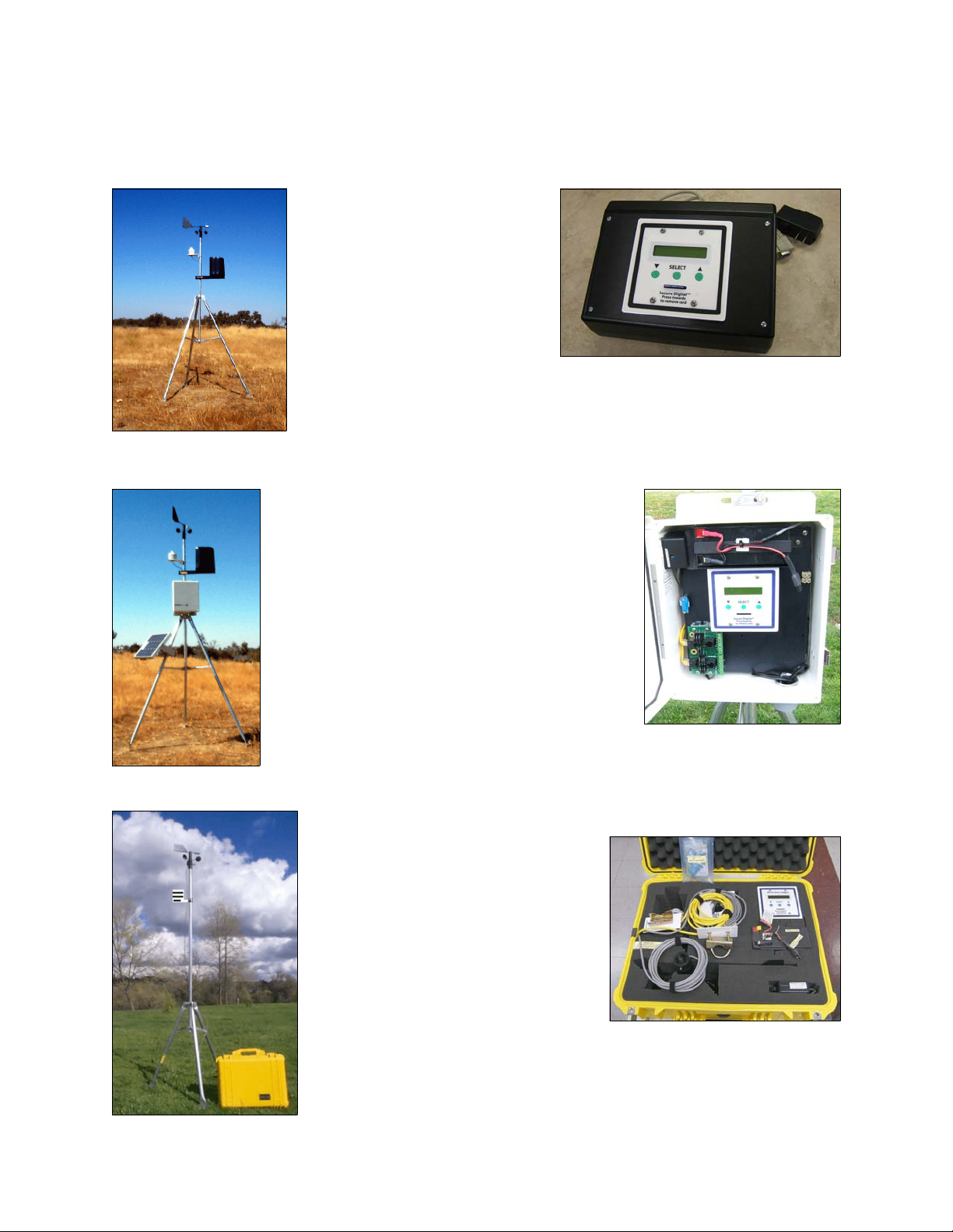
EQUIPMENT CONFIGURATION AND IDENTIFICATION
WMS-25
Modular Weather Station
WMS-25-DL Desktop Data Logger with Display
with AC Power Adapter and Serial Output Cable
WMS-25-NEMA
Modular Weather Station
with Optional Solar Panel Charger
WMS-25-NEMA-DL Data Logger in NEMA Enclosure
with 12V 7AH Battery & AC Charger, Surge Protection
WMS-25-P
Portable Weather Station
WMS-25-DL-P or -PRH
Data Logger in Carrying Case
with 12V 7AH Battery & AC Charger
Page 5

OMEGA
Model WMS-25 Weather Station
Instruction Manual
1.0 INTRODUCTION
The WMS-25 Modular Weather Stations are meteorological systems designed to be a
“user friendly” solution for data storage and real-time monitoring of weather conditions.
This manual covers all three versions: Desktop, NEMA, and Portable. The data logger
and general operation is the same on all versions.
The standard sensor package includes 6 weather parameters: wind speed and
direction, temperature and relative humidity, barometric pressure, and precipitation,
(additional optional sensors can be added), a 5-foot tripod and 5-foot vertical mast for
sensor mounting, and a data logger with LCD display. The portable systems have a
3-foot tripod with 6-foot mast. Pressure and rain sensors are optional.
No computer is required for setup and viewing data. A simple menu interface using the
LCD display and three front panel buttons makes setup easy.
Data is recorded directly to a Secure Digital (SD™) card, providing convenient data
downloads and storage for many months of data. The data logger is compatible with
standard SD cards up to 2GB. Logging at 1 minute intervals, a 2GB card will store over
5 years of data. A new file is created and saved to the card each day.
An RS232 serial output is standard and allows real time viewing of the data on a PC
with any terminal emulator program, for example HyperTerminal, Putty, or the optional
WMS-25-STR Graphical Display Software.
Using the stored recorded data is simple. The SD card is removed from the logger,
inserted into the SD card reader, then plugged in to the USB port on your computer
(Windows, Macintosh, and Linux). This will then show up as a drive. To view and graph
the data, click on the file corresponding to the day of interest. Microsoft Excel,
OpenOffice.org, or any spreadsheet program can be used to view, graph, and analyze
your data.
Typical data sample showing one line:
2016-06-15 13:51:50,4.2,10.1,190,,,,,,,,,0.04,223,12.14,,,,57.807,67.471,28.700,,192
1
Page 6

2.0 DESCRIPTION
The WMS-25 Weather Station has been set up and configured for the six standard
sensors: speed, direction, temperature, humidity, barometric pressure, and rainfall. It
has been shipped for a plug and play operation.
Data Logger
The WMS-25 data logger’s easy-to-use interface includes a 16-character by 2-line
backlit LCD screen, which displays current information and is used for configuring the
data logger. A simple menu-driven interface using the LCD and three front panel
buttons makes setup easy. A bright back-light makes the data logger easy to use at
night. A Secure Digital (SD™) card slot makes recording and accessing data easy.
Sensors
The standard WMS-25 sensors have been designed to be rugged, compact, and
lightweight. They interface directly to the data logger without the need for additional
signal conditioning.
Wind Speed and Direction ~ WMS-25-WSD
The wind sensor combines a three-cup anemometer and a wind vane on a single axis.
The anemometer is a contact-type wind sensor which, when rotated by the wind,
triggers a series of momentary switch closures that are directly related to wind speed.
The wind vane uses a 20K ohm potentiometer to sense direction changes. Depending
on the position of the potentiometer wiper, an analog voltage is output that corresponds
to the position of the vane. By orienting the vane to North (360 degrees) during
installation, wind can be easily calculated from the output voltage. The resolution of the
wind vane is 1 degree (azimuth display) or 16 compass points (on LCD display only).
Barometric Pressure ~ WMS-25-BP (optional on portable stations)
The barometric pressure sensor is set for sea level when it leaves the factory.
It will read absolute pressure. Barometric pressure varies with elevation, the data logger
can be set up to read corrected to sea level pressure for the elevation at which it is
installed. This is done adding the correct offset in inches in the analog setup menu. You
will need to know the correction in inches for the elevation at your location before you
change it. Instructions are provided in the manual.
Temperature and Relative Humidity ~ WMS-25-TH
The WMS-25-TH is a combination temperature and relative humidity sensor installed a
solar radiation shield. Temperature and humidity are sensed using a sensor element
which changes voltage with temperature and humidity fluctuations. (The warm-up time
to stabilize is 10 minutes.)
2
Page 7
Rain ~ WMS-25-RG (optional on portable stations)
The 8 inch rain gauge with mast mounting arm provided with the WMS-25 is a
traditional tipping bucket design. Resolution is 0.01 inches (0.254 mm) per tip.
3.0 CONFIGURATION AND OPERATION
Data Logger
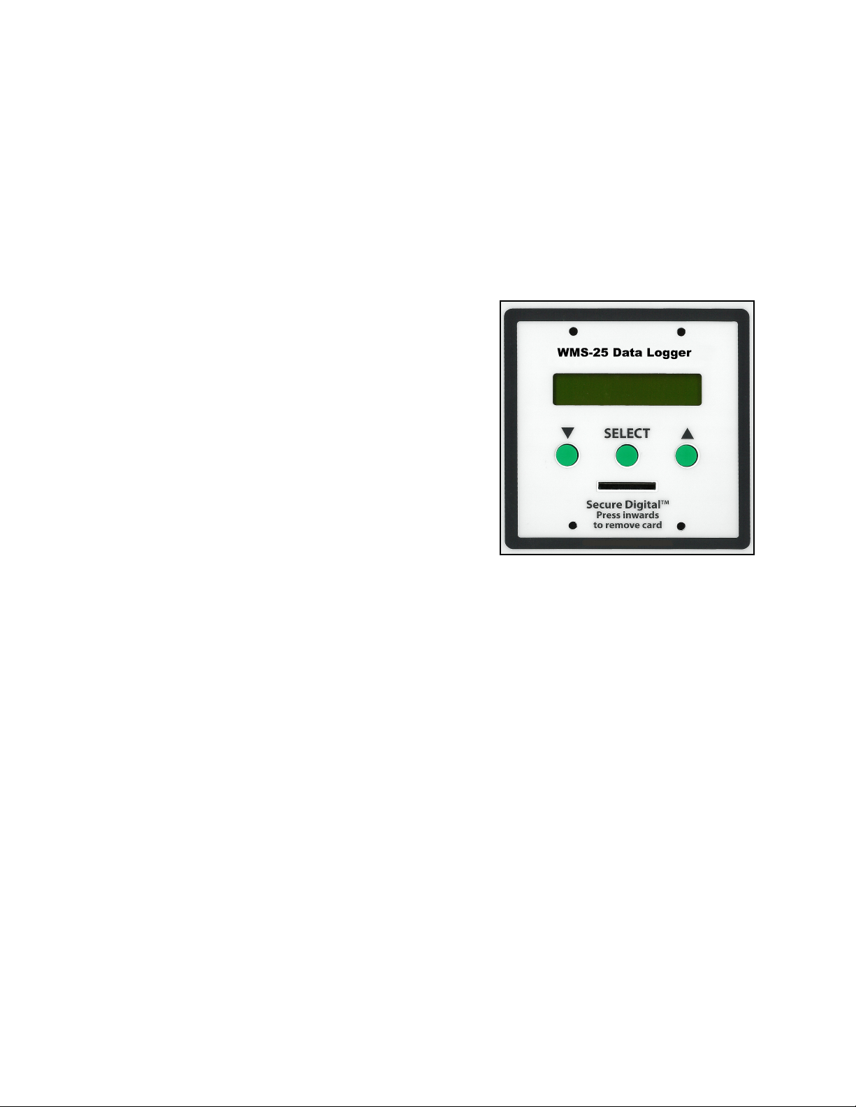
Navigation Buttons
Scrolls through display screens and allows user
setup menus. Moves values in the negative
direction.
SELECT Press to enter ‘Setup’ menu.
Scrolls through display screens and allows
setup menus. Moves values in the positive
direction.
All buttons respond to a single press. Holding a
button will not cause multiple actions to occur.
Secure Digital™ Card Slot
The data logger has a spring-loaded memory card slot. To insert a Secure Digital™
(SD™) card, place the card face up into the slot on the front panel and press the card
inwards until the card clicks into place. To remove card, press the card slightly inward
and the card will release.
The card should not be removed by pulling it out without first pressing it inwards. If a
card is pulled out in this manner, both the memory card and the card socket may be
damaged.
Menus
On the data logger display, the primary menus are: Main Setup Menu, Wind
Channels, Analog Channels, and Counter Channels. Submenus of the Main Setup
Menu are: Date Setup, Time Setup, Anemometer Setup, Wind Vane Setup, Log
Interval, Counter Setup, Analog Setup, Channels to Log, RS232 Setup, Wind Vane
Setup, Site Name Setup, Sync. Setup, and Restore Defaults. The wind data logger
has three keys: which moves backwards or down (depending on the screen);
SELECT which selects, sets, or moves to the next character; and which moves
forwards or up (depending on the screen). Since the WS-25 logger has been
pre-configured, there is no need to go into the sensor setup menus.
3
Page 8
Setting the Time and Date
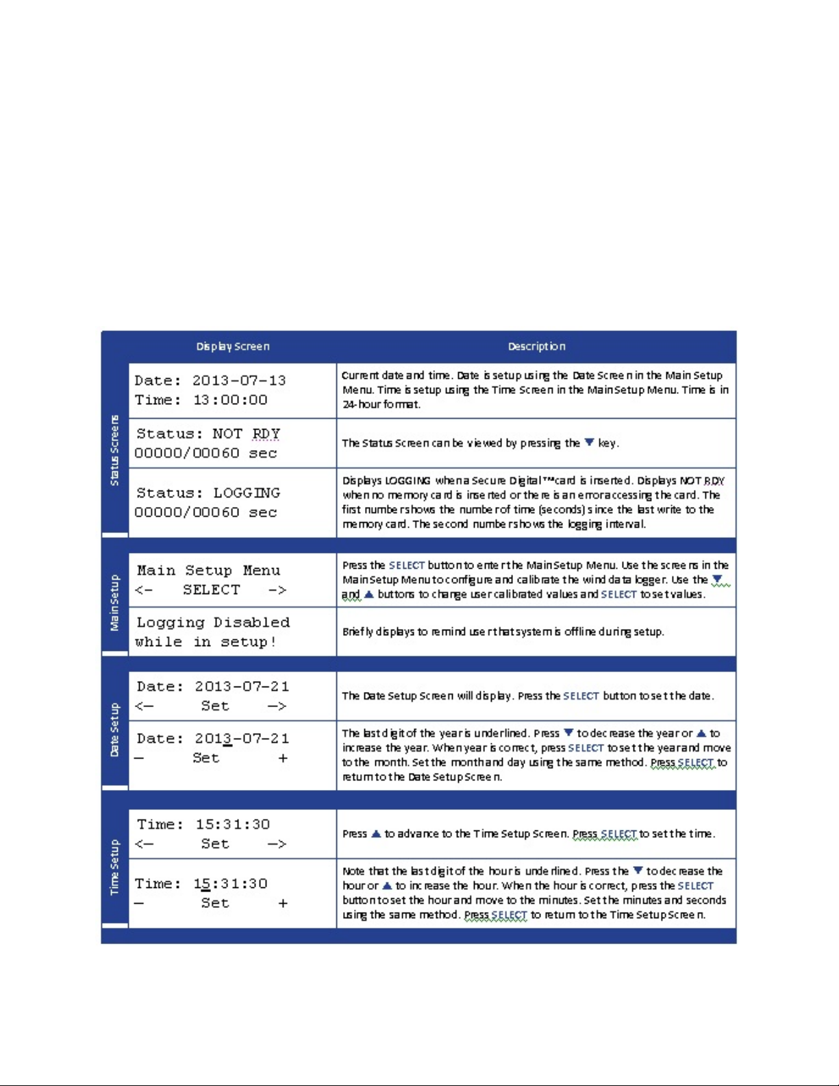
Using the ‘Time’ and ‘Date’ screens, one can both view and set the current date and
time. The wind data logger incorporates a real-time clock that keeps accurate time while
power is disconnected. The clock does not automatically adjust for daylight savings;
however it does automatically adjust for leap years. The date format used throughout
the wind data logger is YYYY-MM-DD.
See the CONFIGURATION AND OPERATION Table below for sample screen shots
and detailed instructions for changing time and date. The same method is used with all
data logger setup screens.
1 minute logging at the top of the minute :00 has been selected rather then free running
4
Page 9
Data Logging
The WMS-25 data logger can record measurements directly to an industry standard
Secure Digital™ or Multi-Media Card™. The data logger records both raw and
processed values in a simple text format that can be opened with any spreadsheet or
text editor.
Starting and Stopping Logging
Logging commences after the memory card is inserted into the data logger and
terminates after it is removed. Use the Logging Status screen to verify that the data
logger is recording. If a memory card is inserted but the data logger shows “NOT
READY” then there is a problem and the data logger WILL NOT record anything. Check
to be sure the card is fully inserted and meets the memory card requirements outlined
below.
Memory Card Requirements
The WMS-25 data logger is compatible with all sizes of SD (Secure Digital™) or MMC
(Multi-Media Card™) cards; however, it will not work with Secure Digital High Capacity
(SDHC) cards.
There is no need to format the SD card for this data logger mode.
Data
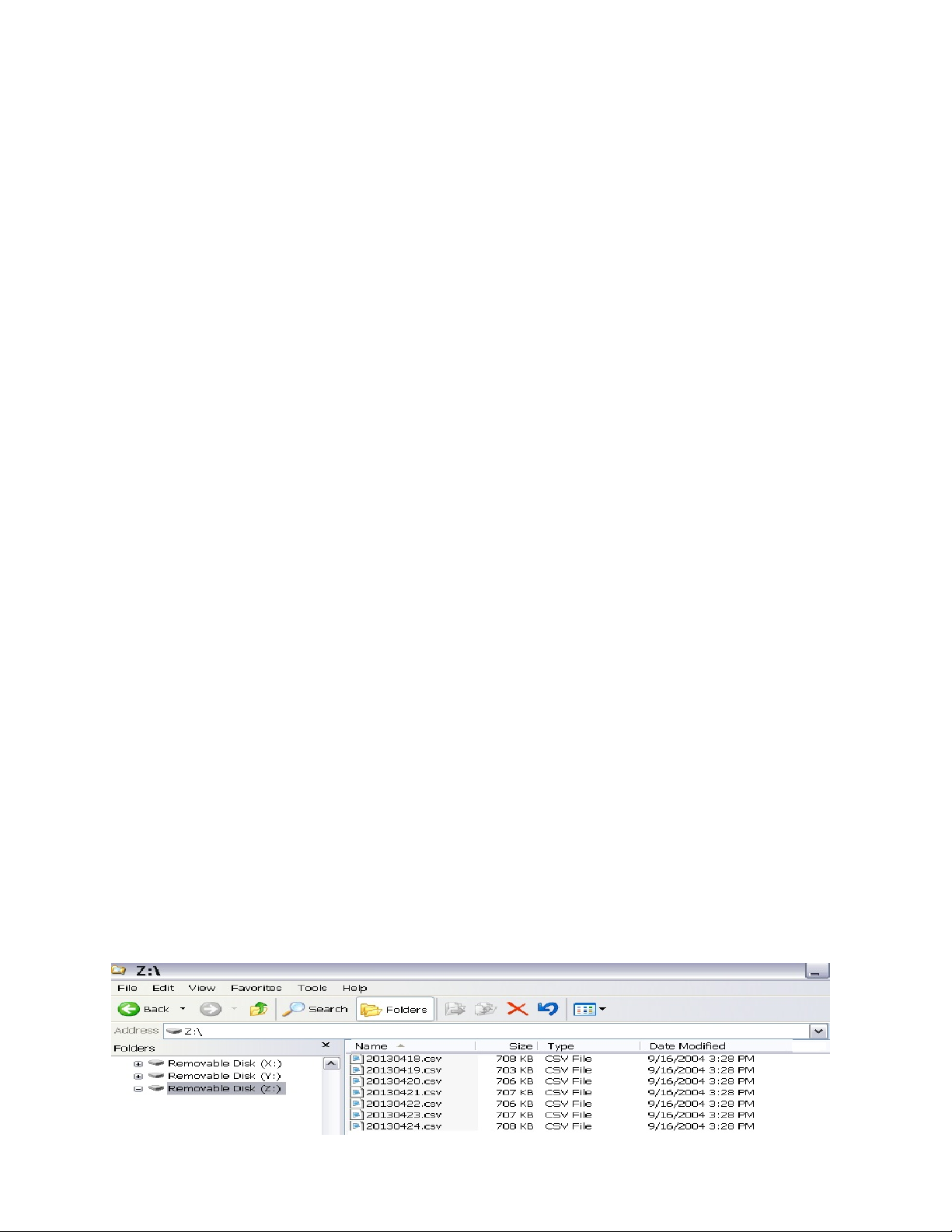
The WMS-25 data logger generates one file per calendar day. The file name is
YYYYMMDD.CSV (ex. 20160713.CSV) where YYYY is the four-digit year, MM is the
two-digit month, and DD is the two-digit day. Each file is stored in the main directory or
folder of the SD or MMC. The data logger also writes two other files that contain meta
information about the channels being logged. For most applications these files can be
ignored. The file consists of one record per line. On most computers, a single file can
be opened in a text editor by simply double clicking on its icon.
The data logger records Comma Separated Variable (CSV) files to the memory card.
CSV data can be used by nearly any spreadsheet software. First launch the program,
then use the ‘Open’ command in the File menu to select the CSV file created by the
data logger. (The date modified column has no function and can be ignored.)
5
Page 10

Microsoft Excel, Gnumeric, and Open Office.org Calculator are all good spreadsheet
programs. Gnumeric and OpenOffice.org Calc are free and can be downloaded from
the Internet.
2016-06-15 00:02:30,1.9,3.0,19,,,,,,,,,0.00,88,12.18,,,,71.829,28.556,965.721,,67
2016-06-15 00:02:31,2.3,2.3,16,,,,,,,,,0.00,91,12.14,,,,71.829,28.556,965.455,,120
4.0 INSTALLATION
Installation of the WMS-25 is simple and straightforward, thanks to its modular design
and terminal-strip connections.
1. Set up the tripod and vertical mast, and secure it.
2. Mount the sensors Wind, RH/T, Rain Gauge on the tripod.
3. Connect the sensor cables wires to the data logger.
4. Apply power the WMS-25 Logger.
5. Confirm and/or set the correct date and time.
6. Scroll thru the channels to verify the proper readings on the display.
7. Insert the SD memory into the logger. (Data is logged once a minute. This can be
changed as needed.)
8. A RS232 serial output is available for direct connections to a PC.
9. Done.
Refer to the “Quick Start” instruction booklet for sensor wiring connections,
power connections, and other special information.
Tripod Towers
The five-foot tripod tower provided with the WMS-25 is constructed of steel tubing for
durability and strength. Horizontal bracing is a feature of the tripod tower. The tripod’s
foot brackets can be bolted onto a concrete foundation or a wooden platform. The wind
speed and direction sensor mounts on top (the tapered end) of the five-foot aluminum
sensor mast. The solar radiation shield (for the temperature and humidity sensor) and
the rain gauge mounting arm are supplied with u-bolts to clamp onto this mast. For
stability, we recommend that the mast be inserted into both of the tripod’s collar clamps.
Guy kits are recommended for areas of high winds and ground kits are recommended
for areas with lightning activity.
The WMS-25P Portable Stations include a 3-foot tripod, with two 3-foot mast that
connect together end to end.
Caution: When installing the wind sensor, make sure that the sensor and cable are well
clear of any power lines.
6
Page 11

Lightning Protection and Grounding
A copper lightning protection ground lug, located on the data acquisition NEMA module,
this is the path to ground for all of the lightning protection circuitry in the
WMS-25-NEMA.
Connect a heavy copper wire to this lug the other end connects to a grounded outlet or
water pipe or Earth ground. In areas subject to severe lightning activity, we recommend
that you install a grounding rod.
Power Connections
The WMS-25 runs on 12Vdc power. It can be operated from a standard AC/DC power
adapter connected to a 110-240 Vac outlet, or from a 12Vdc battery on NEMA and
portable versions.
Main Memory Battery Backup
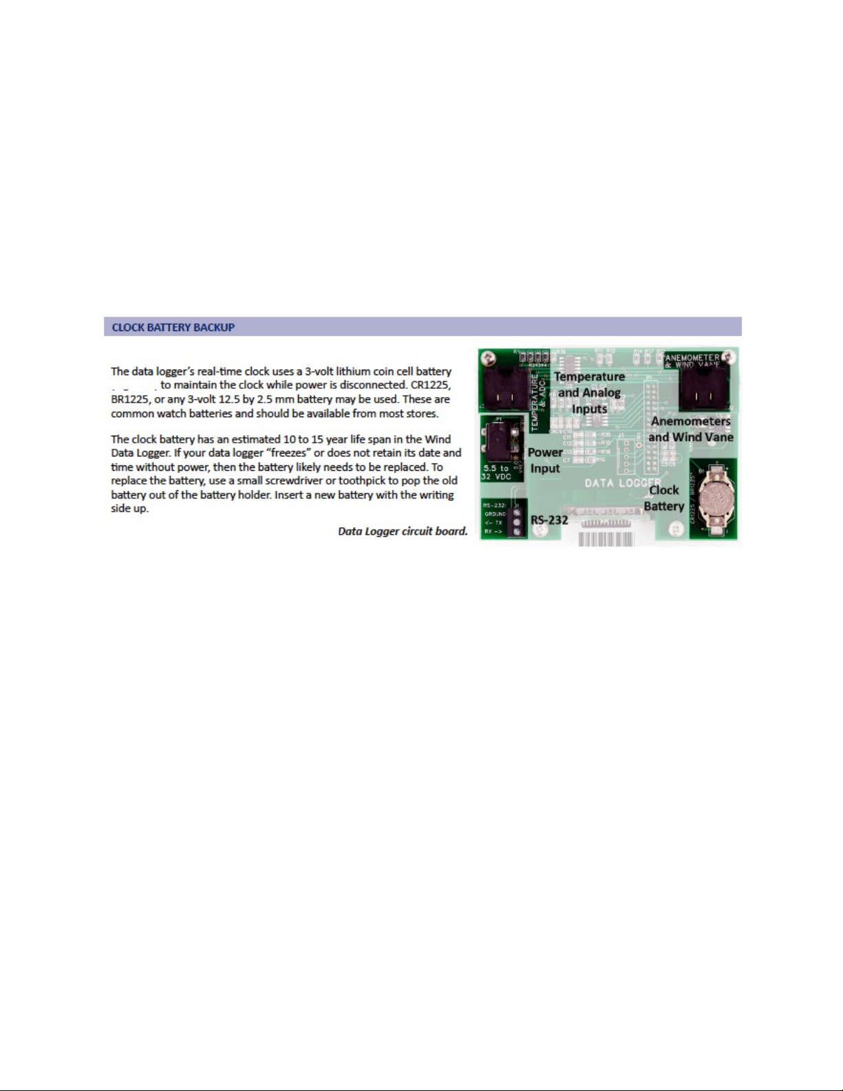
The WMS-25 main memory has a lithium battery backup so setup parameters, as well
the date and time stored data, will be retained even if the primary power source is
interrupted.
RS232 Interface
An RS232 interface is available, but not needed. It is used when connecting the
optional real time graphical display software to a PC.
The standard text data can be viewed on any terminal program. A new line on data will
be sent out every minute.
Sample data ....
2016-06-15 00:02 :3 0,1 .9 ,3.0,19,,,,,,,,,0 .00 ,8 8,12.18,,,,71.829 ,28.5 56,965 .7 21,,6 7
2016-06-15 00:02 :3 1,2 .3 ,2.3,16,,,,,,,,,0 .00 ,9 1,12.14,,,,71.829 ,28.5 56,965 .4 55,,1 20
The WMS-25 serial data communication between the user and the WMS-25 is
accomplished using RS232 communications protocol designed for short-distance use.
The standard 6-foot serial interface cable that connects the data logger to the computer
is terminated with a 9-pin “D” connector. The serial cable can be extended up to 200
feet.
For computers without a serial port, a USB-to-Serial converter may be used. When
installing the converter, be sure to note the Com port number it is assigned.
7
Page 12

Certain communications parameters must be specified in the computer to enable the
two devices to communicate. Using a communications software program such as
HyperTerminal, TeraTerm, or Putty, set them as follows:
Bits per second 9600
Data bits 8
Parity None
Stop bits 1
Flow control None
Emulation ANSI
Testing the Connection
Once the WMS-25 is connected to the computer, the connection can be tested by
turning the power on to the WMS-25. If the RS232 connection is sound, a line of data
will show every minute.
2016-06-15 16:02:30,1.9,3.0,19,,,,,,,,,0.00,88,12.18,,,,71.829,38.556,29.721,,67
A RS232 Output Tester Light is supplied with the unit. If the serial output is functioning,
the red light should flash every minute.
If the WMS-25 is functioning but you see nothing on the PC screen, the wrong serial
port may be selected. Try selecting Com 3 or another functioning serial port. You can
see a list of available ports in Computer > System Properties > Device Manager >
Ports.
Sensor Installation
Install the sensors in their chosen locations. Run cables from the sensors to the data
logger location, with no cable exceeding the maximum allowable length listed below.
Sensor Maximum Cable Length
Wind* 200' (66m)
T/RH* 150' (82m)
Rain* 200' (66m)
Barometric Pressure** 10' (3m)
Solar Radiation* (optional) 100' (33m)
*Std cable length 40' **Std cable length 18"
When the sensors have been installed and the cables run, connect and test them as
described in the following sections. Refer to the hook-up drawing at the back of this
manual to verify wire colors and physical connections.
8
Page 13
Data Logger
The data logger is configured at the factory for the following sensors. English US units
are the default, but metric units will be programmed on request. The units can be
changed to English or metric, as needed, in the sensor setup menus.
1. Wind speed and direction
2. Barometric pressure (optional on WMS-25-P portable stations)
3. Temperature and Relative Humidity
4. Rain Gauge (optional on WMS-25-P portable stations)
9
Page 14

Advanced Information
These are the WMS-25 DEFAULT SETTINGS for programming each channel using standard
WMS-25 sensors with English units.
Anemometer 0
m = +0001.2500 W MS-25-W SD (for m /s m = +0.567 , fo r knots m = +1.10, fo r k m h m = +2 .0 0)
b = +0000.0000
l = WIND SPEED
u = MPH (u = M /S, u = KT S , u = k m h)
Anemometer 1
m = +0001.2500
b = +0000.0000
l = WIND SPEED
u = MPH
Anemometer 2
m = +0001.2500
b = +0000.0000
l = WIND SPEED
u = MPH
WIND VANE SET UP
Linear *
Dir Offset 000°
Log Interval
Log Sec 00060
Counter Setup
Counter 0 OK As Is
Counter 1 OK As Is
Counter 2
m = +0000.0100 WMS-25-RG (for millimeters m = +0000.250)
b = +0000.0000
l = RAIN TODAY
u = IN (u = mm)
ANALOG SET UP
Analog 0 OK As Is
m = +0008.000
b = +000.0000
l = INPUT VOLTAGE
u = VDC
Analog 1 OK As Is
m = + 0001.000
b = + 0000.0000
l = WIND DIR
u = VDC
10
Page 15

Analog 2
m = +0598.8020
b = +0000.0000
l = SOLAR RAD
u = W/M
Analog 3 Aux. temp only
m = +0180.000 For degrees C m = +0100.0000
b = -0459.6900 For degrees C b = -0273.1500
l = AUX TEMP
u = °F For degrees C u = °C
Analog 4
m = +0070.9092 For degrees C m = + 0039.394
b = -0022.0000 For degrees C b = -0030.0000
l = TEMPERATURE
u = °F For degrees C u = °C
Analog 5
m = +0030.3030
b = +0000.0000
l = HUMIDITY
u = %
Analog 6 * The b value will be different on each sensor
m = +0006.4375 for millibars m = +0218.0000, for millimeters m = 0163.5134
b = +0003.6600 * for millibars* b = +0124.5400, for millimeters * m = 00090.9
l = BARO.PRESSURE
u = IN for millibars u = mb or hpa, for millimeters u = mm
Analog 7
m = +0001.0000
b = +0000.0000
l = EXT ADC
u = VDC
Channels to Log (these 7 are enabled, the others are disabled)
Anemometer 0 (wind speed)
Counter 2 (rainfall daily total)
Wind Direction (wind direction)
Analog 0 (battery voltage or DC power input)
Analog 4 (temperature)
Analog 5 (humidity)
Analog 6 (barometric pressure)
RS232 Enabled
Baud: 9600
SITE NAME
WMS25
11
Page 16

Data Record Format Information on Memory Card
There are no description headers generated on the stored data. 23 Fields are generated, but
only the ones being used are saved. The ,,, is where the missing fields would appear if they
were needed.
Sample data with the 6 Standard Sensors connected WMS-25-DL 1 min logging, English units
Date and Tim e, Spee d , Gust, Spd coun t,,,,,,,,, Rain, W Dir, inVo lts, Tem p °F , Hum % , B P inhg, cksum
2016-06-15 02:19:00, 0.3, 0 .9 , 19 ,,,,,,,,, 0.00, 351, 12.14,,,, 8 3.1, 26 .7, 28.473,, 230
2016-06-15 02:20 :0 0,0 .7 ,1.2,28,,,,,,,,,0 .00 ,3 51,12.14,,,,83.1,26.7,28.465,,95
2016-06-15 02:21 :0 0,0 .9 ,1.4,31,,,,,,,,,0 .00 ,3 51,12.14,,,,83.1,26.7,28.465,,8
Sample data with the 4 Standard Sensors connected WMS-25-P,1 min logging, English units
Date and Tim e, Spee d , Gust, Spd coun t,,,,,,,,,, W D ir, In p u t Voltag e, Temp °F, H u m idity % , cksu m
2016-06-15 17:58:00, 4.9, 2 2.2, 27 7 ,,,,,,,,,, 24 9, 13 .0 8,,,, 73.30 1, 18 .0 88,,, 198
2016-06-15 17:59 :0 0,2 .7 ,12.6 ,128,,,,,,,,,,269,13.04 ,,,,73 .387,18.310 ,,,3 6
2016-06-15 18:00 :0 0,3 .2 ,3.5,83,,,,,,,,,,315,1 3.08,,,,73.474,18 .4 58,,,44
Many WMS-25-DL are setup in metric units with m/s, °C, millimeters and millibars.
Refer to the Quick Start As Shipped sheet for your exact setup.
Converting Wind Speed Pulse Count to Average Wind Speed
The ‘Wind Pulses’ screen in the Main Display Loop shows the number of anemometer
revolutions since the last write to the memory card. The pulse count information can easily be
converted to average wind speed using the following formula:
Average Wind Speed = ((WCx/sample_interval) * anemo_m) + ( anemo_b)
Example using the following snippet of data from the data logger WMS-25-WSD sensor and a
sampling interval of 60 seconds recording in MPH:
2016-06-15 16:11:00,18.0,19.4,810
As seen in the data snippet above or the reading from the data logger ‘Wind Pulse’ screen,
WC0 = 810. This information can then be used with the formula above:
Average MPH = ((810/60) * 1.25) + 0.0 = 16.87 MPH
A complete data logger manual with internal PCB schematics is available upon request.
12
Page 17

WARRANTY/DISCLAIMER
OMEGA ENGINEERING, INC. warrants this unit to be free of defects in materials and workmanship for a
period of 13 months from date of purchase. OMEGA’s WARRANTY adds an additional one (1) month
grace period to the normal one (1) year product warranty to cover handling and shipping time. This
ensures that OMEGA’s customers receive maximum coverage on each product.
If the unit malfunctions, it must be returned to the factory for evaluation. OMEGA’s Customer Service
Department will issue an Authorized Return (AR) number immediately upon phone or written request.
Upon examination by OMEGA, if the unit is found to be defective, it will be repaired or replaced at no
charge. OMEGA’s WARRANTY does not apply to defects resulting from any action of the purchaser,
including but not limited to mishandling, improper interfacing, operation outside of design limits,
improper repair, or unauthorized modification. This WARRANTY is VOID if the unit shows evidence of
having been tampered with or shows evidence of having been damaged as a result of excessive corrosion;
or current, heat, moisture or vibration; improper specification; misapplication; misuse or other operating
conditions outside of OMEGA’s control. Components in which wear is not warranted, include but are not
limited to contact points, fuses, and triacs.
OMEGA is pleased to offer suggestions on the use of its various products. However,
OMEGA neither assumes responsibility for any omissions or errors nor assumes liability for
any damages that result from the use of its products in accordance with information provided
by OMEGA, either verbal or written. OMEGA warrants only that the parts manufactured by the
company will be as specified and free of defects. OMEGA MAKES NO OTHER WARRANTIES OR
REPRESENTATIONS OF ANY KIND WHATSOEVER, EXPRESSED OR IMPLIED, EXCEPT THAT OF
TITLE, AND ALL IMPLIED WARRANTIES INCLUDING ANY WARRANTY OF MERCHANTABILITY
AND FITNESS FOR A PARTICULAR PURPOSE ARE HEREBY DISCLAIMED. LIMITATION OF
LIABILITY: The remedies of purchaser set forth herein are exclusive, and the total liability of
OMEGA with respect to this order, whether based on contract, warranty, negligence,
indemnification, strict liability or otherwise, shall not exceed the purchase price of the
component upon which liability is based. In no event shall OMEGA be liable for
consequential, incidental or special damages.
CONDITIONS: Equipment sold by OMEGA is not intended to be used, nor shall it be used: (1) as a “Basic
Component” under 10 CFR 21 (NRC), used in or with any nuclear installation or activity; or (2) in medical
applications or used on humans. Should any Product(s) be used in or with any nuclear installation or
activity, medical application, used on humans, or misused in any way, OMEGA assumes no responsibility
as set forth in our basic WARRANTY/DISCLAIMER language, and, additionally, purchaser will indemnify
OMEGA and hold OMEGA harmless from any liability or damage whatsoever arising out of the use of the
Product(s) in such a manner.
RETURN REQUESTS/INQUIRIES
Direct all warranty and repair requests/inquiries to the OMEGA Customer Service Department.
BEFORE RETURNING ANY PRODUCT(S) TO OMEGA, PURCHASER MUST OBTAIN AN AUTHORIZED
RETURN (AR) NUMBER FROM OMEGA’S CUSTOMER SERVICE DEPARTMENT (IN ORDER TO AVOID
PROCESSING DELAYS). The assigned AR number should then be marked on the outside of the return
package and on any correspondence.
The purchaser is responsible for shipping charges, freight, insurance and proper packaging to prevent
breakage in transit.
FOR WARRANTY RETURNS, please have the
following information available BEFORE contacting
OMEGA:
1. Purchase Order number under which the product
was PURCHASED,
2. Model and serial number of the product under
warranty, and
3. Repair instructions and/or specific problems
relative to the product.
OMEGA’s policy is to make running changes, not model changes, whenever an improvement is possible. This affords
our customers the latest in technology and engineering.
OMEGA is a registered trademark of OMEGA ENGINEERING, INC.
© Copyright 2015 OMEGA ENGINEERING, INC. All rights reserved. This document may not be copied, photocopied,
reproduced, translated, or reduced to any electronic medium or machine-readable form, in whole or in part, without the
prior written consent of OMEGA ENGINEERING, INC.
FOR NON-WARRANTY REPAIRS,
OMEGA for current repair charges. Have
the following information available BEFORE
contacting OMEGA:
1. Purchase Order number to cover the COST
of the repair,
2. Model and serial number of the product, and
3. Repair instructions and/or specific problems
relative to the product.
consult
Page 18

Where Do I Find Everything I Need for
Process Measurement and Control?
OMEGA…Of Course!
Shop online at omega.com
TEMPERATURE
MU
Thermocouple, RTD & Thermistor Probes, Connectors, Panels & Assemblies
MU
Wire: Thermocouple, RTD & Thermistor
MU
Calibrators & Ice Point References
MU
Recorders, Controllers & Process Monitors
MU
Infrared Pyrometers
PRESSURE, STRAIN AND FORCE
MU
Transducers & Strain Gages
MU
Load Cells & Pressure Gages
MU
Displacement Transducers
MU
Instrumentation & Accessories
FLOW/LEVEL
MU
Rotameters, Gas Mass Flowmeters & Flow Computers
MU
Air Velocity Indicators
MU
Turbine/Paddlewheel Systems
MU
Totalizers & Batch Controllers
SM
pH/CONDUCTIVITY
MU
pH Electrodes, Testers & Accessories
MU
Benchtop/Laboratory Meters
MU
Controllers, Calibrators, Simulators & Pumps
MU
Industrial pH & Conductivity Equipment
DATA ACQUISITION
MU
Data Acquisition & Engineering Software
MU
Communications-Based Acquisition Systems
MU
Plug-in Cards for Apple, IBM & Compatibles
MU
Data Logging Systems
MU
Recorders, Printers & Plotters
HEATERS
MU
Heating Cable
MU
Cartridge & Strip Heaters
MU
Immersion & Band Heaters
MU
Flexible Heaters
MU
Laboratory Heaters
ENVIRONMENTAL
MONITORING AND CONTROL
MU
Metering & Control Instrumentation
MU
Refractometers
MU
Pumps & Tubing
MU
Air, Soil & Water Monitors
MU
Industrial Water & Wastewater Treatment
MU
pH, Conductivity & Dissolved Oxygen Instruments
M-5586/07/16
 Loading...