

Page 1
omega.com
e-mail: [email protected]
For latest product manuals:
omegamanual.info
User’s Guide
WM7600
M-4374/1006
Shop online at
Page 2

Servicing North America:
USA: One Omega Drive, P.O. Box 4047
ISO 9001 Certified Stamford CT 06907-0047
TEL: (203) 359-1660 FAX: (203) 359-7700
e-mail: [email protected]
Canada: 976 Bergar
Laval (Quebec) H7L 5A1, Canada
TEL: (514) 856-6928 FAX: (514) 856-6886
e-mail: [email protected]
For immediate technical or application assistance:
USA and Canada: Sales Service: 1-800-826-6342 / 1-800-TC-OMEGA
®
Customer Service: 1-800-622-2378 / 1-800-622-BEST
®
Engineering Service: 1-800-872-9436 / 1-800-USA-WHEN
®
TELEX: 996404 EASYLINK: 62968934 CABLE: OMEGA
Mexico: En Espan˜ol: (001) 203-359-7803 e-mail: [email protected]
FAX: (001) 203-359-7807 [email protected]
Servicing Europe:
Benelux: Postbus 8034, 1180 LA Amstelveen, The Netherlands
TEL: +31 (0)20 3472121 FAX: +31 (0)20 6434643
Toll Free in Benelux: 0800 0993344
e-mail: [email protected]
Czech Republic: Frystatska 184, 733 01 Karviná, Czech Republic
France: 11, rue Jacques Cartier, 78280 Guyancourt, France
TEL: +33 (0)1 61 37 2900 FAX: +33 (0)1 30 57 5427
Toll Free in France: 0800 466 342
e-mail: [email protected]
Germany/Austria: Daimlerstrasse 26, D-75392 Deckenpfronn, Germany
TEL: +49 (0)7056 9398-0 FAX: +49 (0)7056 9398-29
Toll Free in Germany: 0800 639 7678
e-mail: [email protected]
United Kingdom: One Omega Drive, River Bend Technology Centre
ISO 9002 Certified Northbank, Irlam, Manchester
M44 5BD United Kingdom
TEL: +44 (0)161 777 6611 FAX: +44 (0)161 777 6622
Toll Free in United Kingdom: 0800-488-488
e-mail: [email protected]
OMEGAnet®Online Service Internet e-mail
www.omega.com [email protected]
It is the policy of OMEGA to comply with all worldwide safety and EMC/EMI regulations that
apply. OMEGA is constantly pursuing certification of its products to the European New Approach
Directives. OMEGA will add the CE mark to every appropriate device upon certification.
The information contained in this document is believed to be correct, but OMEGA Engineering, Inc. accepts
no liability for any errors it contains, and reserves the right to alter specifications without notice.
WARNING: These products are not designed for use in, and should not be used for, human applications.
Page 3

TABLE OF CONTENTS
SPECIFICATIONS………………………………………3
INSTALLATION…………………………………………4
SETUP ACCESS………………………………………..5
MENU LAYOUT...………………………………………6
CONFIGURATION……………………………………..7
REMOTE SERIAL DISPLAY………………………….8
CALIBRATION………………………………………….9
SERIAL PORTS………………………………………10
SERIAL COMMUNICATIONS……………………….11
ANALOG OUTPUT……………………………………13
DIGITAL INPUT/OUTPUT……………………………15
SETPOINTS……………………………………………17
OVER/UNDER…………………………………………17
BATCH MODE…………………………………………18
TIME & DATE………………………………………….19
WEIGH IN/OUT………………………………………..20
SMART SERIAL……………………………………….23
ASCII CHART………………………………………….28
DISPLAY MESSAGES………………………………..32
115/220 VAC…………………………………………..33
2
Page 4

SPECIFICATIONS
Truck IN/OUT operation: Up to 300 stored transactions
Smart Serial Setup: 8 custom print files plus 8 macro files, 30 characters each.
Batch Start/Stop: Control from front panel or remote input.
Setpoint Operation: 4 output relays configurable for normal setpoints, over/under or
manual/auto batch modes.
LOAD CELL A/D CONVERTER
TYPE: 24 bit delta sigma
EXCITATION: 5 VDC, 120 mA max.
SIGNAL INPUT: 16 mv
SENSITIVITY: 0.1 uV/grad
UPDATE RATE: 30 update/second
DISPLAY: Six (6) Decades, 0.6 inch LED
KEYPAD: Full numeric plus controls
POWER INPUT: 117/217 VAC, 50-60 HZ, 20 watts, fuse 0.25 A Slo-Blow.
SERIAL PORTS:
Port 1: RS232C or 20ma
Port 2: RS485, RS232C or 20mA.
ENCLOSURE: Stainless Steel, NEMA 4x, Tilt - Stand Base, 7lbs.
CASE: 9” (w) x 6.44” (h) x 4” (d) Tilt or panel mount.
OPTIONS:
TIME & DATE: 12/24 hr, battery backed.
ANALOG OUTPUT: 0-10v, 4-20ma (16 bit D/A).
DIO: 4 AC/DC – inputs, 4 AC outputs (SS Relays, 0.5 amp)
Optional Case: 10” (w) x 6.5” (h) x 4” (d) Tilt only.
Panel Mount: Kit (replaces tilt stand).
3
Page 5
INSTALLATION
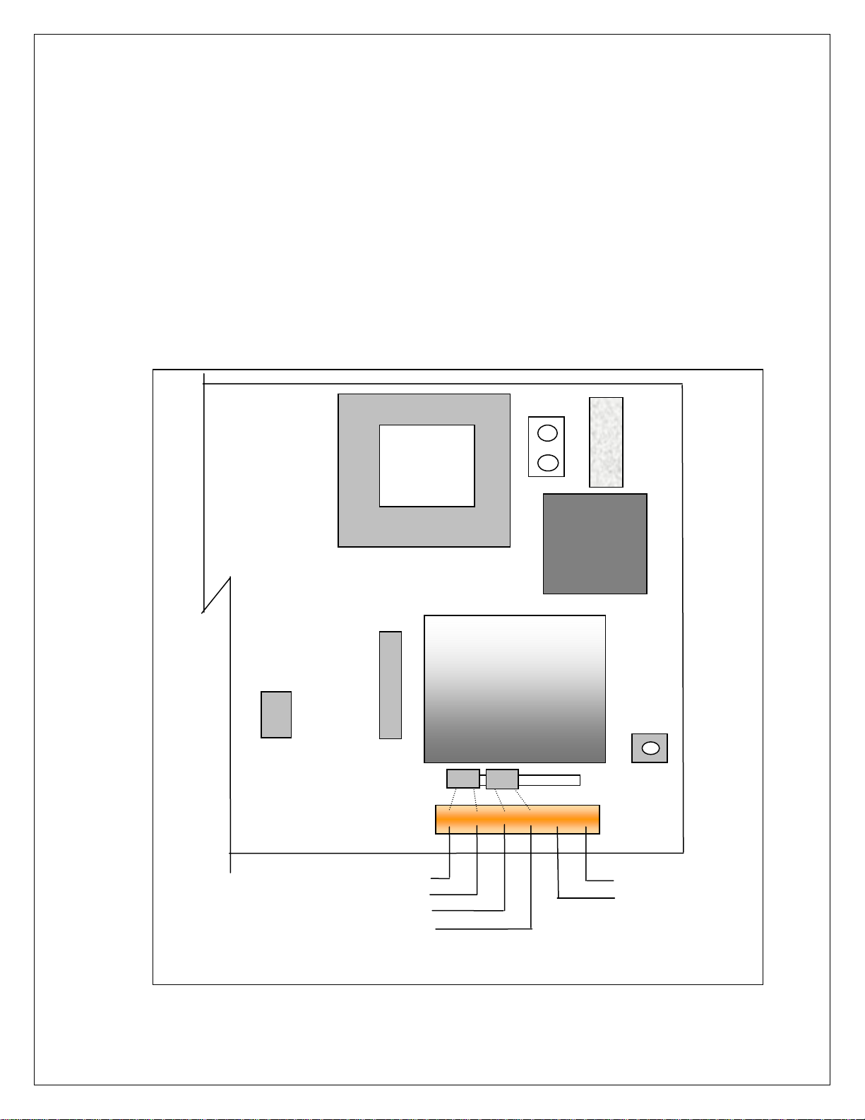
POWER WIRING: The indicator is designed to be operated from 117/217 VAC, 50-60 Hz. The
unit power cord must be plugged into a grounded 3 - wire polarized AC wall socket. All normal
wiring and grounding precautions should be observed, including use of a "clean" AC power
line.
SCALE WIRING:The unit is equipped with cable gland entry for load cell cable insertion and
internal (pluggable) terminal strip for 4 / 6 wire connection. Remove sense jumpers P11-8/7,
P11-6/5 for six wire.
Transformer
P12
F1
0.25A
SB
Line
Filter
1 2
A
J1
B
P5
Shielded
A/D Converter
8 7 6 5 P11
SW4
CAL
EW-1000 Rev…..
6 5 4 3 2 1 TB-1
Excitation +
Sense +
Excitation –
Sense -
Signal +
Signal -
4
Page 6
SETUP ACCESS
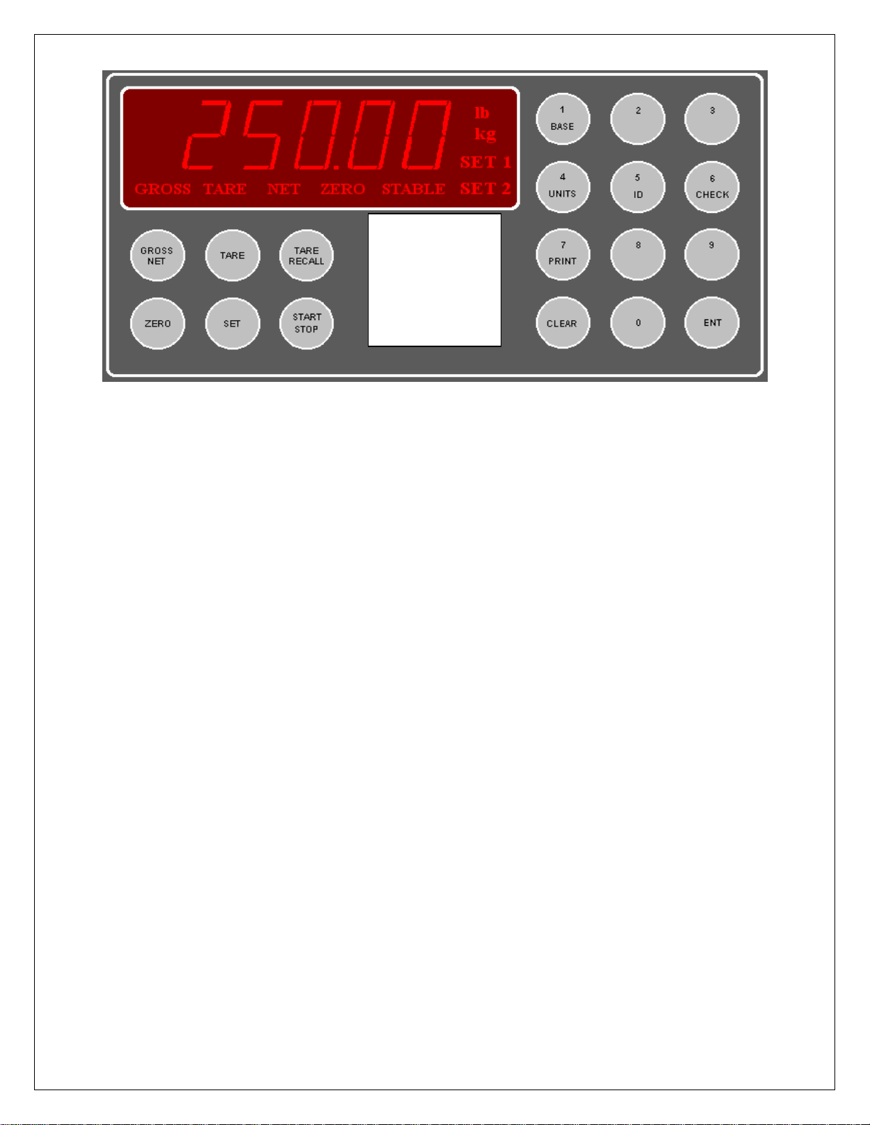
To access instrument configuration, calibration or to enable options, depress the “Zero” key for
five seconds.
The Audit Trail counters (“Pxxxx” and “Cxxxx”) are displayed first followed by access code
request (“AC?”). The initial factory setting is “0000” which can be entered with four steps of the
“0” key (“AC0000”) and “ENT”. If no entry is made, instrument returns to operate mode.
The access code can be changed to any four digit combination during setup exit when display
again shows “AC?”.
The “Check” key provides the software version “V 1.XX” followed by the display test routine.
Use the “ENT” key to advance to the keyboard test and to exit tests.
After entry, use the “Tare Recall” key to select a main menu; configuration (“SEL.CFG”),
calibration (“SEL.CAL”), or options (“SEL.OPX”) and “Start/Stop” to back step.
The “Gross/Net” key enters selected menu and is used to step through sub categories.
Individual parameter selection is made with the “Tare/Recall” key, which then steps through
the parameter choices (“Zero” key back steps within the menu).
The “ENT” key is used at any point to “back” up from categories to menus and to “save?” and
“AC?” and exit.
During the exit steps, if changes were made, the display is “save?” with alternate “no”. To save
changes, use the “Units” key to select “yes” and “ENT” to exit.
Calibration numeric entries are entered directly followed with the “ENT” key.
Front panel access is inhibited if conventional “sealing” is applied by
setting jumper J1-1 in the B position. The board mounted “CAL” button is
then used for access.
5
Page 7
Menu Layout
CFG
CAL
OP1
OP2
OP3
OP4
OP5
OP6
OP7
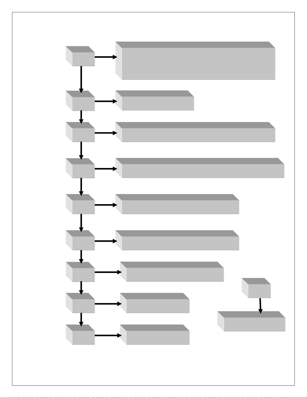
Configuration: Divisions, count by, decimal, over
range, filter, AZM, zero range, ISM, lb/kg, serial port
selection, DIO enable
Calibration: Zero, Span
Analog Output: Gross, Net, Display; Zero, Span, Trim
Setpoint DIO: Setpoint, Over/Under, Manual / Auto Batch
Time & Date: 24 hr, 12 hr, Print format
Weigh – In / Weigh – Out: Truck mode
10 Point Linearity, Filter selection
OP8
Totalizer
AC/DC Battery
Smart Serial
6
Page 8
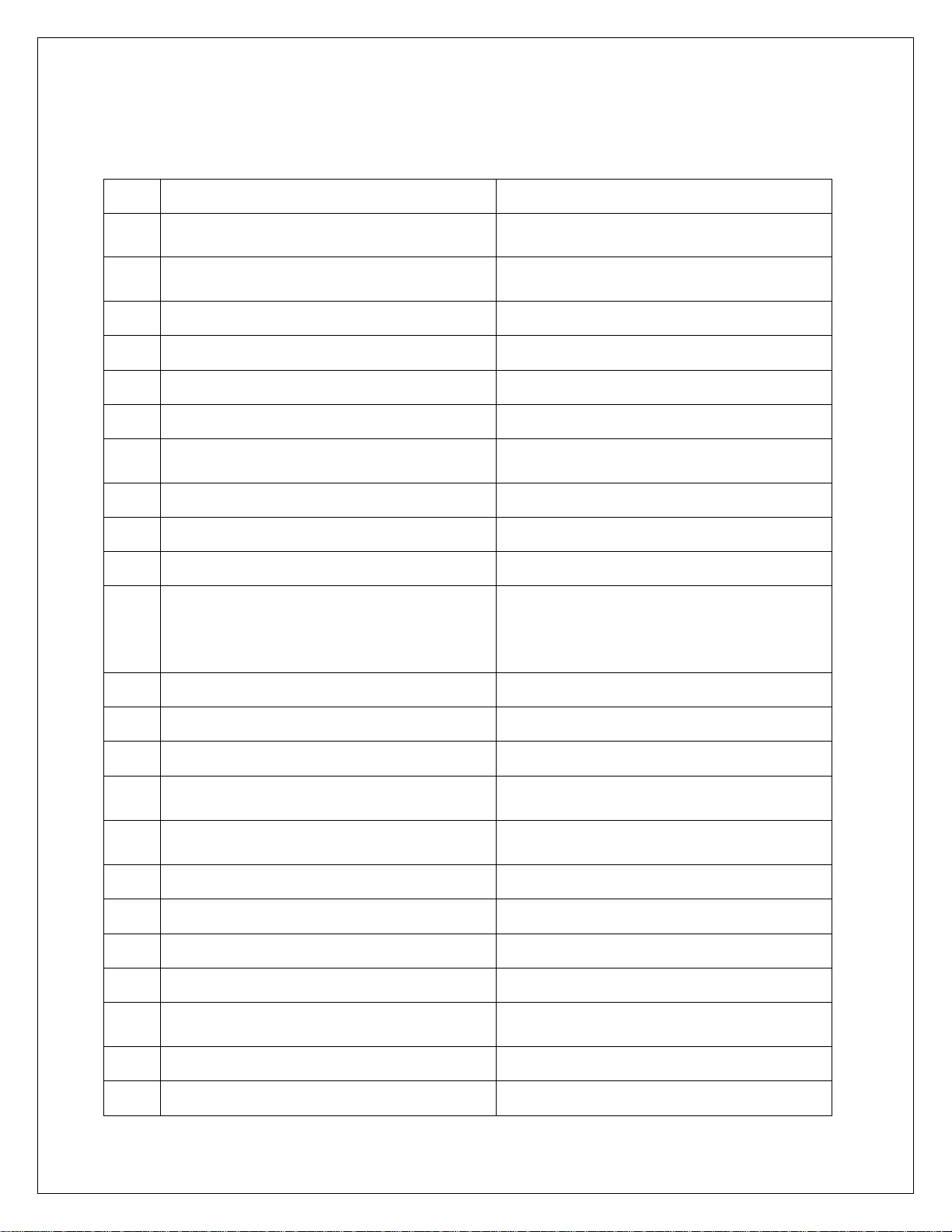
CONFIGURATION: “SEL.CFG” Use Gross/Net to enter the menu and step to each category,
Tare Recall to select parameters. ENT to return to menu selection.
Capacity is the combination of “1”, “2” and “3”.
Example: 1__100, 2___2 and 3__0.0 = 2,000 x 0.2 lb
Step Parameters Definition
1 5, 10, 15, 20…100, 120…1000
2 1, 2, 5, 10, 20, 50, and 100.
Number of divisions x100
100 = 10,000 divisions
Count by selection
10,000 divisions, count by 2 = 20,000
3 0, 0.0, 0.00, 0.000, and 0.0000 Decimal point selection
4 105P, 9 d (105% or 9 divisions) Overrange selection
5 1, 2, 3, 4, 5, 6, 8, 10, 12, 15……90 Digital filter selection (averaging)
6 off, 0.5, 1, 3, 5, 10 (divisions) Auto Zero Maintenance (AZM)
7 1.9, 5, 10, 20, FS (% of capacity)
Zero range selection
1.9% of 2,000 x 0.2 = 38.0 lb
7.1 off, on (ISM) Zero’s scale on power-up
8 off, 1, 3, 5,10 (divisions) Motion Band selection
9 lb, kg, con Units selection and convert
Port 1 serial output selection
10 nt, Gtn, n.nt, n.Gtn.
nt display only, Gtn is Gross Tare Net
and n.nt/n.Gtn inhibit negative gross
printing
11 off, co, de Off, Continuous, or Demand
12 7o, 7E, 8n 7- odd, 7- even or 8- none
13 12, 24, 48, 96 Baud rate selection
14 off, 1, 2, 3, 5, 10, 15 (seconds)
19 A, b
Delay between lines or continuous
output.
A : adds “STX” in continuous
b : No “STX” in continuous
20 nt, Gtn, n.nt, n.Gtn Port 2 serial output selection
21 off, co, de, Ln Off, Continuous, Demand, Network
22 7o, 7E, 8n 7- odd, 7- even or 8- none
23 12, 24, 48, 96 Baud rate selection
24 off, 1, 2, 3, 5, 10, 15 (seconds)
Delay between lines or continuous
output.
25 1 – 16 (RS485/RS422) Network address selection
30 off, on DIO Inputs
7
Page 9
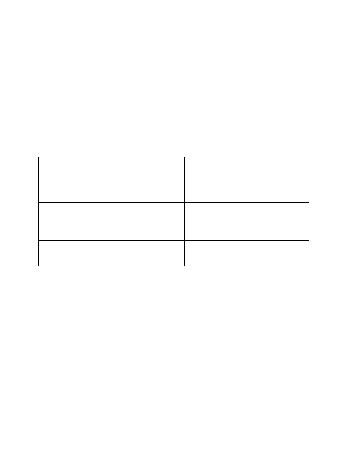
Remote Serial Display (RSD) Option
In RSD mode the instrument can be set to work with another unit as a “remote” either as the
main or the slave unit. Communication is pre-set for channel two only on both units.
(RS232, 9600, 8, none)
When in remote mode, re-access to the following selections requires using the internal “cal”
switch.
Remote unit can have full or partial control of the main unit. Devices are available to replace
the cable for wireless communication.
rd.En : Selects Indicator as Remote
40 rd.OF, rd.En, rd.re
Display (RSD)
rd.re : Allows indicator to operate
w/RSD
41 En.On Allow remote keypad operation
42 Zr.On Enable/Disable zero key
43 tr.On Enable/Disable tare key
44 Un.On Enable/Disable unit key
45 Pr.On Enable/Disable print key
46 Fn.On Enable/Disable all other functions
8
Page 10

CALIBRATION: “SEL.CAL” Use Gross/Net to enter the menu indicated by a flashing “C” on
the left and live weight is displayed. Scale zero (dead load) or adjusting span (single or multipoint) are independent. Therefore either can be done and repeated as necessary before
exciting calibration. If an error has been made, exit without “storing” will return to prior setup.
KEY (FUNCTION) DISPLAY Definition
(Live weight 123 lb) “C”__123 Cal mode scale reading
Zero (acquire dead load) “------“ to “C___0.0” acquires new dead load
(Live weight 5000 lb) “C”__4995 Scale reading with load
Enter numeric value directly:
(Adjustment complete) 005000 adjusted value
Then ENT:
(Adjust span) “------“ to “C” 5000 displays new span
Repeat as required then ENT to exit CAL
“Save ?” “No” or “Save ?” “Yes” use Units to select and ENT to store “yes” with changes or
“no” to exit without changes.
Continue with ENT to “Ent AC” which allows access code change by entering a new four digit
code and ENT or ENT with no entry to maintain current password.
Option 5 Ten point calibration: Allows up to 10 span points (pt1…….pt10). Zeroing the scale
clears the existing values. Points are assigned incrementally with error indication if the addition
is not above the prior point or exceeding scale capacity.
Filter selection included for rolling or box averaging.
5.1 OFF, On Enable 10 point span
5.2 A, b
A : Rolling average
B : Box average
9
Page 11
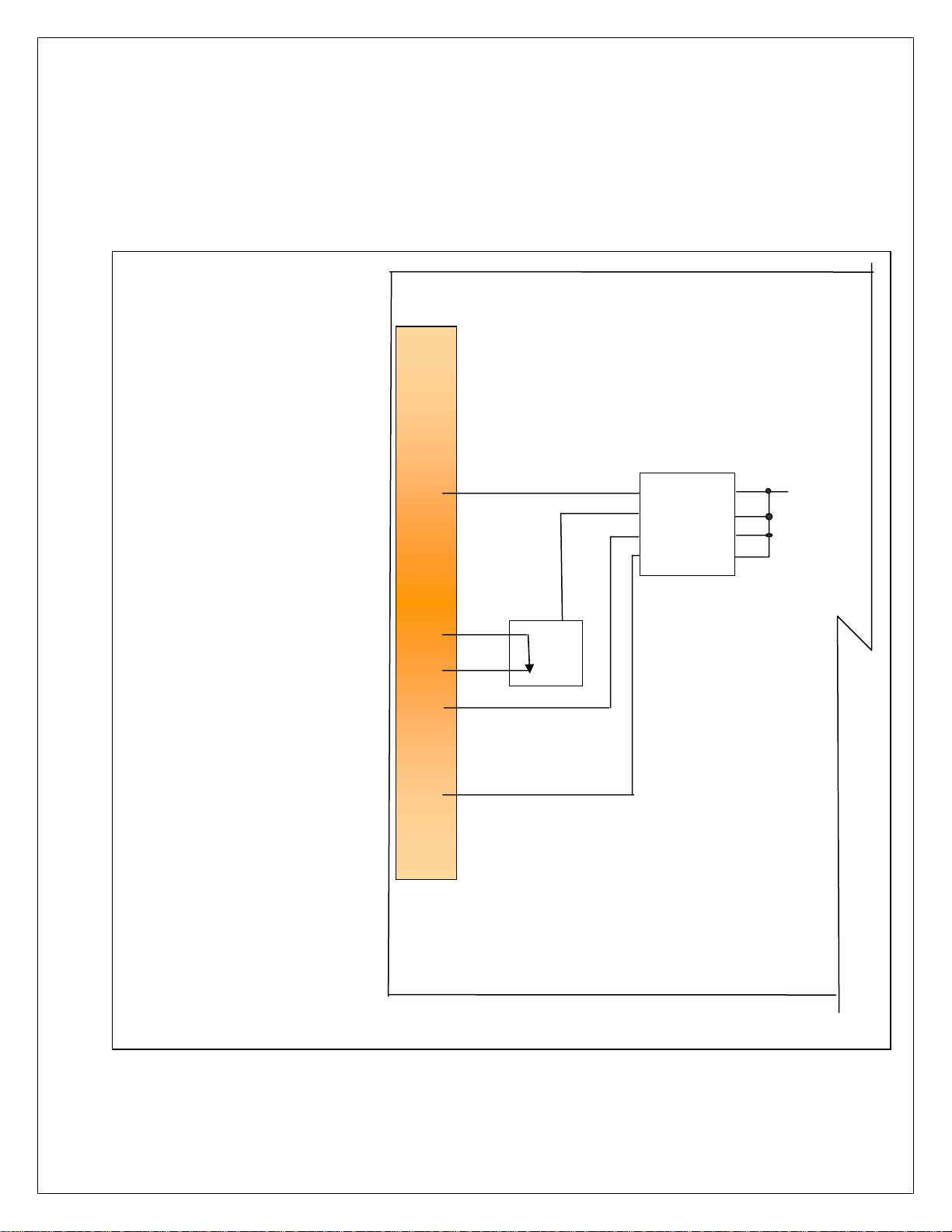
SERIAL PORTS
Port 1: RS232 duplex (Rx,Tx), 20ma (Tx).
Port 2: RS232 duplex (Rx,Tx), 20ma (Rx,Tx), RS485, or RS422.
Note: Position jumper on J2 for Port 2 receive selection.
GND
Tx1, RS232
Rx1, RS232
Tx2, RS232
Rx2, RS232
Tx1, -20ma
Tx1,Tx2,+20ma (5 vdc)
Tx2, -20ma
Rx2,+20ma
Rx2, -20ma
B, RS485, RS422-Tx
A, RS485, RS422-Tx
B, RS422-Rx
A, RS422-Rx
GND
1
2
3
4
5
6
7
8
9
10
11
12
13
14
15
O1
A-RS232
B-20ma
C-RS485
D-RS422
J2
Rx2
EW-1000 Rev…
10
Page 12

Serial Communications
Remote Commands
<Z><cr> Zero Scale “Gross” mode, no motion, inside zero range.
<N><cr> Switch to Net “Gross” mode with Tare stored.
<G><cr> Switch to Gross “Net” mode.
<T><cr> Auto Tare Switch to Net, no motion, not at “Gross” zero.
<P><cr> Print Valid display, No motion
Data Formats
Demand Mode: <stx><pol><DATA><sp><lb/kg><sp><GR/NT><cr/lf>
Continuous Mode: <stx><pol><DATA><L/K><G/N><status><cr/lf>
Brackets “<>” are not sent
Stx: “Start of Text” character (ASCII 002) (can be removed in continuous: config 19)
pol: Polarity sign, “SPACE” (ASCII 032) for positive or (-) sign (ASCII 045) for negative
sp: Space character (ASCII 032)
DATA: Seven (7) digit data field including decimal point or fixed (dummy) zero if selected.
“Leading Zero Suppression” with leading zeros transmitted as “space” characters.
lb/kg: Two (2) character field data identification for weight units, in demand (printer) mode.
Weight in lb = “lb” (ASCII 108,098), weight in kg = “kg” (ASCII 107,103)
L/K: One (1) character field data identification for weight units in continuous (computer)
mode.
Weight in lb = “L” (ASCII 076), weight in kg = “K” (ASCII 075)
GR/NT: Two (2) character field data identification for weighing mode in demand (printer)
mode.
Gross Mode = “GR” (ASCII 071,082), Net Mode = “NT” (ASCII 078,084)
11
Page 13

G/N: One (1) character field data identification for weighing mode in continuous
(computer) mode.
Gross Mode = “G” (ASCII 071), Net Mode = “N” (ASCII 078)
status: One (1) character data identification used in the continuous (computer) output
mode to identify the status of the indicator. Characters are listed below in order of priority.
Calibration/configuration <D> (ASCII 068)
Over/Under Range <O> (ASCII 079)
Motion <M> (ASCII 077)
Center of Zero <C> (ASCII 067)
None of the above <sp>(ASCII 032)
cr/lf: Two (2) character field, “Carriage Return” (ASCII 013), “Line Feed” (ASCII 010)
Guidelines for Serial Output:
Demand format will inhibit “print” when scale is in “motion” or with negative “Gross” weight, even
in “Net” mode (based on setting “CFG 10”).
Local Network Protocol:
Command to the indicator:
<*><DD><00><cmd><data entry><CR>
Response from indicator:
<:><00><DD><cmd echoed><data resp><CR>
Where: (<,> brackets not sent)
* = Message from master (2AH)
DD = Indicators address
00 = Master address (fixed at 00)
CR = Message terminator (ODH)
: = Response from indicator (3AH)
cmd = Command to indicator
cmd ech = Command echoed from indicator
data ent = Data entered into indicator
data resp = Data response from indicator
12
Page 14
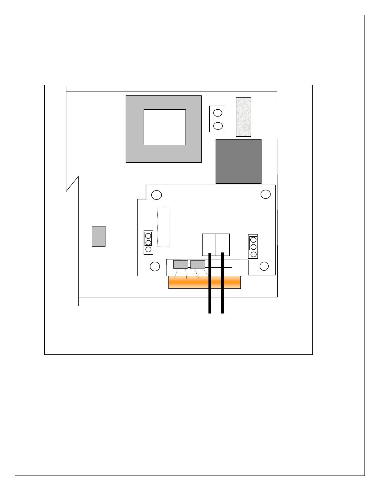
OPTION 1: Analog Output
0 – 10 Vdc or 4 – 20 ma, select with jumpers J1 and J2
Transformer
P12
P5
EW-1000-AOUT
A
J1
B
1 2
V
J1
I
TB 20
1 2
- +
8 7 6 5 P11
EW-1000 Rev…..
6 5 4 3 2 1 TB-1
0 – 10 Vdc or 4 – 20 ma
Position J1 & J2 for V/I
- +
13
F1
Line
Filter
0.25A
SB
J2
V
I
Page 15

Option 1 Analog Output: “SEL.OP1” Use Gross/Net to enter the menu and step to
each category, Tare Recall to select parameters. ENT to return to menu selection.
DISPLAY Parameters Definition
1.1__Gr Gr, Net, DSP Analog tracks gross, net or display
“1.5__Zr” “000” (flashes current analog starting point)
Adjust value and ENT to adjust starting point.
“1.6__FS” “500” (flashes current analog span point)
Adjust value and ENT to adjust full scale.
1.7__ZrA While monitoring the output, use Start/Stop to decrease, Tare Recall to
increase the analog reading (Zero trim digi-pot).
1.8__FSA While monitoring the output, use Start/Stop to decrease, Tare Recall to
increase the analog reading (Span Trim digi-pot).
ENT to exit OP1.
14
Page 16
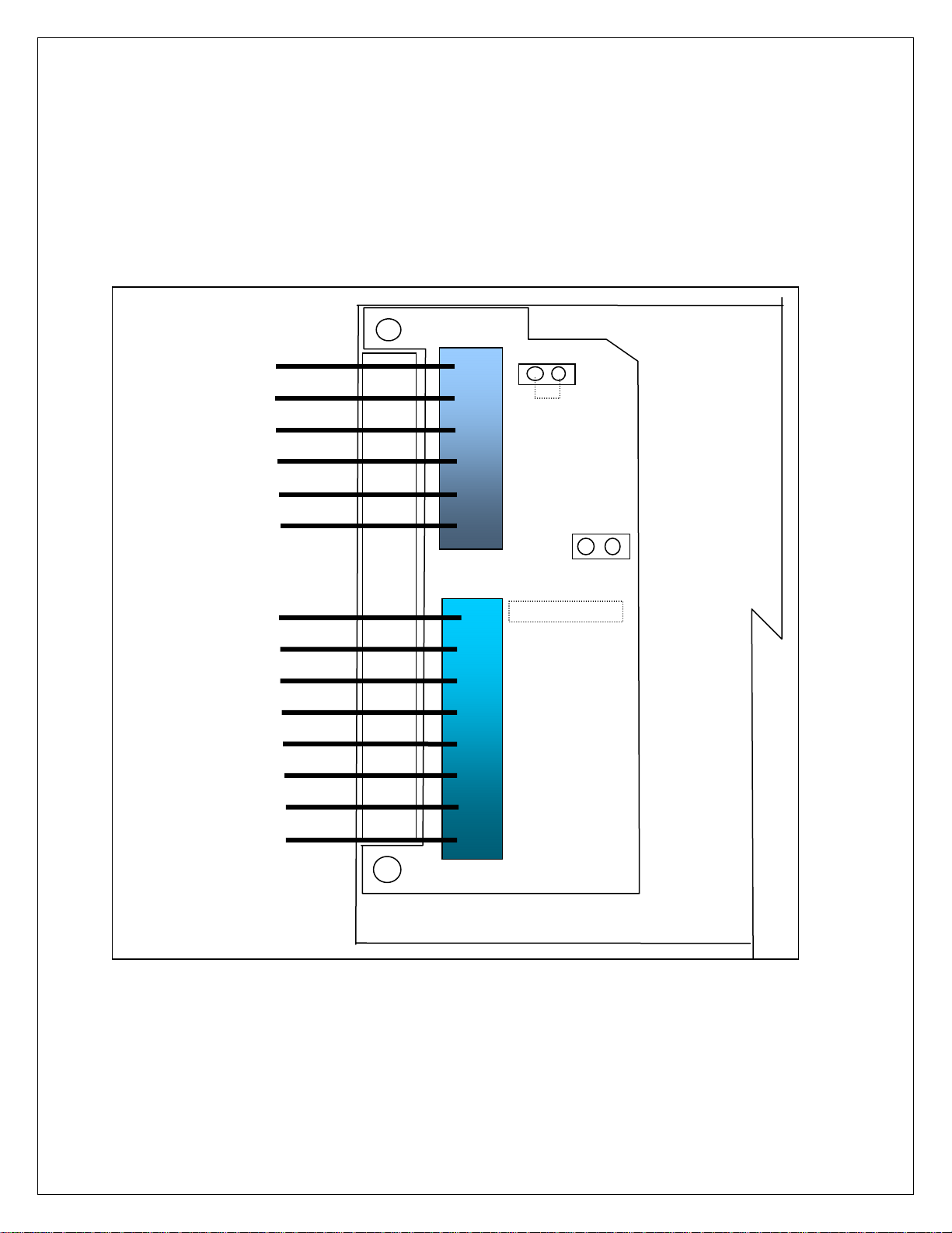
OPTIONS 2: DIO
AC Inputs; D1, D2 are not installed, J1 = short (underside), J2 = open, R1 – R4 = 18k
(3w, 5%, flame proof).
DC Inputs; D1, D2 are installed, J1 = open (cut trace), J2 = short, R1 – R4 = 1.5k (1/2w,
5%, carbon film). AC Outputs; Solid State Relays, 120VAC, 0.5A.
TB 30
COM
COM
IN 1
IN 2
IN 3
IN 4
1
2
3
4
5
6
J1
J2
K1 OUT 1
K2 OUT 2
K3 OUT 3
K4 OUT 4
D1
D2
1
2
3
4
5
6
7
8
EW-1000-DIO
P4
TB 31
EW-1000 Rev…
.
15
Page 17
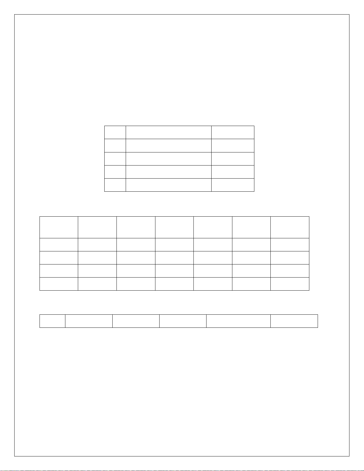
Option 2 DIO: “SEL.OP2” First select the operating mode for “Setpoint”, “Over/Under”,
“Manual or Auto Batch”. After setup, the parameters for the selection are entered from
the weighing mode.
Use Gross/Net to enter the menu and step to each category, Tare Recall to select
parameters. ENT to return to menu selection.
Note: external Inputs are enabled in Configuration with “CFG 30”.
DIO Inputs can be configured for 120vac, 5vdc or dry contact.
IN 1 Gross/Net Stop
IN 2 Tare Start
IN 3 Zero Zero
IN 4 Print Print
DIO Outputs are 120vac (0.5 amp) or optional 24 vdc, based on operating mode:
Normal Batch
Dual Setpt 1 Setpt 2 Ov/Un Man B Auto B
Out 1 Setpt1-A Main 1 Main 1 Low Main 1 Main 1
Out 2 Setpt1-B Fast F1 Fast F1 Accept Fast F1 Fast F1
Out 3 Setpt2-A Tol Main 2 High Main 2 Main 2
Out 4 Setpt2-B Zero B Fast F2 Zero Zero Fast F2
Checkweigher “Bar” graph legends:
Ck1-3 Out Low Low Accept High Out High
Setpoint values are entered from “Weighing Mode” by the SET key and direct numeric
entry.
Weight errors of any kind (e.g., ol, ul, etc) will de-energize all relay outputs and abort a
batch if one is in progress.
Four outputs are available to use as two setpoints with main and fast feed, single
setpoint main and fast feed plus tolerance and zero band. Also Pre-Act can be applied
to the main, for material in-flight compensation.
16
Page 18
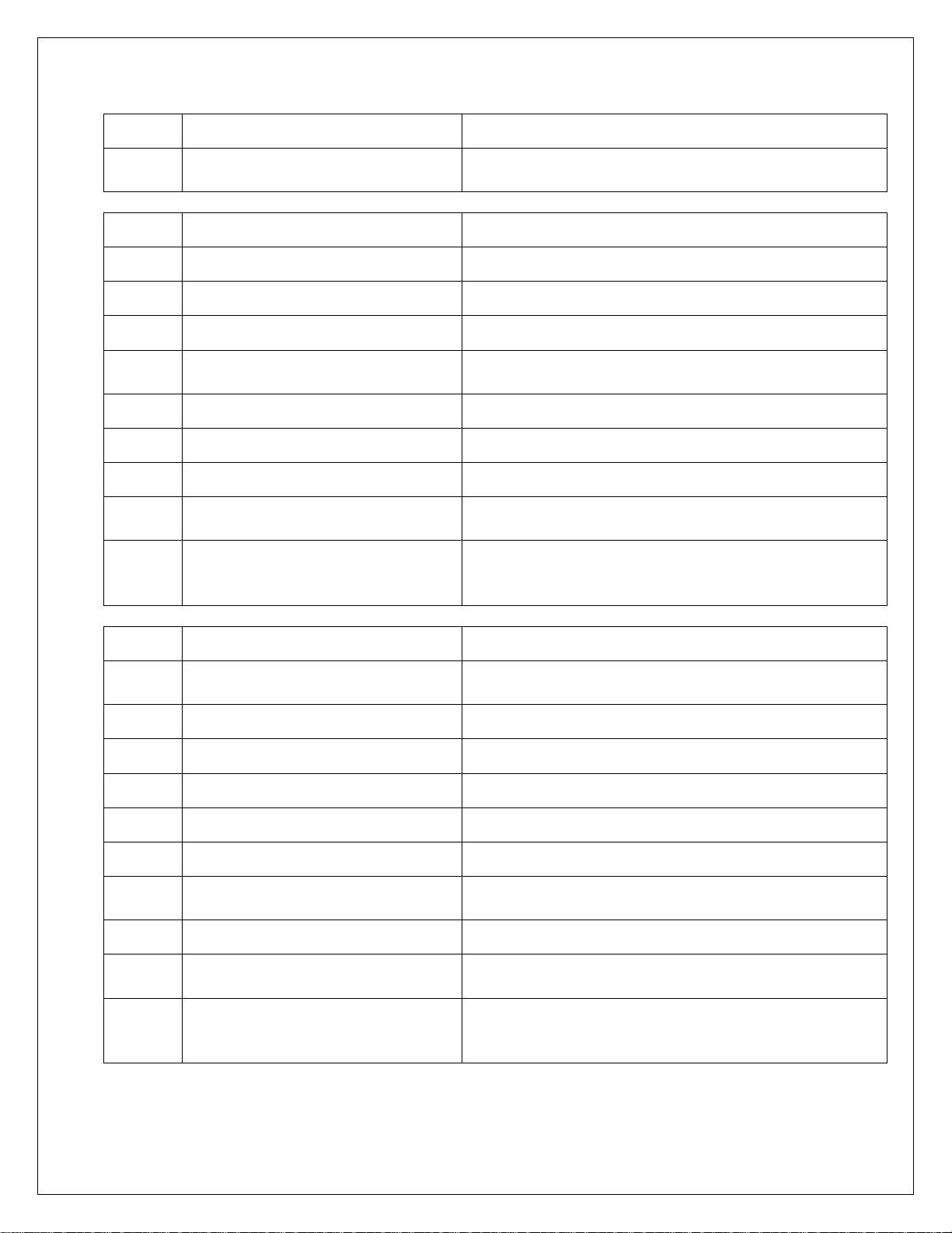
Step Parameter Definition
2.0 OFF, SP, OU.UN, bAt1, bAt2
2.0 SP
2.2
2.3
2.4
2.6
2.7
2.8
2.10
2.11
Off, s1, s1.p, s1.d, s.p.d, Dual Setpoint. 1 + pre-act, + drib, + both, Set1-A&B.
Gr, nt, dSP, Count Setpoint 1 tracks Gross, Net, Display, Count
POS, ZER Output on below reading (POS), inverted (ZER)
Off, s2, s2.p, s2.d, s2.p.d, tOL,
Dual
Gr, nt, dSP, Count Setpoint. 2 + pre-act, + dribble, + both
POS, ZER Output on below reading (POS), inverted (ZER)
ZbO Zero band output (input weight value)
Off, On
SP1.trG (Target) = 1000
s.p.d
example
SP1.PrE (Pre-act) = 5
SP1.drb (Dribble) = 10
Mode select: setpoint, over/under (check
weighing), Manual Batch, Auto Batch
Setpoint
Setpoint. 2 + pre-act, + dribble, + both,
Tolerance, Set2-A&B.
Hysteresis, provides 3 grads to prevent relay
chatter
Main and Fast Feed are on until reading reaches
990, then Fast Feed turns off and Main continues
until Pre-act at 995
2.0 OU.UN
2.2
2.3
2.4
2.5
2.6
2.10
2.11
2.12
HL
example
Off, HL, tGt, Ck1, Ck2, Ck3
Gr, net, dSP Outputs track Gross, Net, Display
POS, ZER Invert low
POS, ZER Invert accept
POS, ZER Invert high
ZbO Zero band output (input weight value)
Off, On
Off, On Enables “Bar” graph legends
Low = 950
High = 1050
Target = 1000
tGt
example
Low = 50
High = 50
Over/Under – check weighing
High/Low band, Target and +/- band, Check
Weigher 1-3.
Hysteresis, provides 3 grads to prevent relay
chatter
Then low is on until 950, then accept is on until
1050 and high is on above 1050.
Outputs match above example for HL
17
Page 19
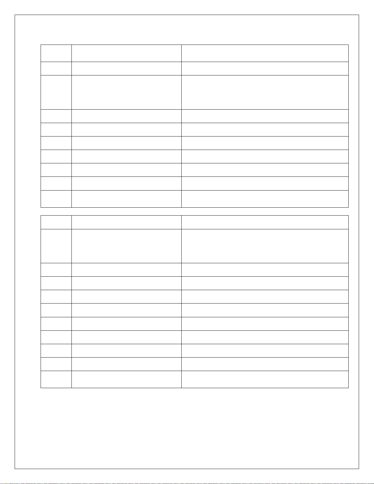
Note: Batch printouts are from Port 1
only
2.0 Bat 1
2.1
2.2
2.3
2.4
2.6
2.7
2.8
2.10
2.0 Bat 2
2.1
Prn, tAr, dln
Off, s1, s1.p, s1.d, s.p.d Setpoint. 1 + pre-act, + dribble, + both
Gr, nt, dSP, Count Setpoint 1 tracks Gross, Net, Display, Count
POS, ZER Output on below reading (POS), inverted (ZER)
Off, s2, s2.p, s2.d, s2.p.d Setpoint. 2 + pre-act, + dribble, + both
Gr, nt, dSP, Count Setpoint. 2 + pre-act, + dribble, + both
POS, ZER Output on below reading (POS), inverted (ZER)
ZbO
Prn, tAr, dln
Manual Batch mode, pauses between setpoints
7400 uses print, tare or external (DIO) for start.
Pressing any key other than “start” will pause and
a second push will abort. 7600E uses Start/Stop
panel switch
Zero band output (input weight value), available if
S2 dribble not used
Auto Batch mode, continues without pause
7400 uses print, tare or external (DIO) for start.
Pressing any key other than “start” will pause and
a second push will abort. 7600E uses Start/Stop
panel switch
2.10
2.2
2.3
2.4
2.5
2.6
2.7
2.8
2.9
Off, s1, s1.p, s1.d, s.p.d Setpoint. 1 + pre-act, + dribble, + both
Gr, nt, dSP, Count Setpoint 1 tracks Gross, Net, Display, Count
POS, ZER Output on below reading (POS), inverted (ZER)
Off, 1, 2, 3, …., 10 Time Delay (settling) before print
Off, s2, s2.p, s2.d, s2.p.d Setpoint. 2 + pre-act, + dribble, + both
Gr, nt, dSP, Count Setpoint. 2 + pre-act, + dribble, + both
POS, ZER Output on below reading (POS), inverted (ZER)
Off, 1, 2, 3, …., 10 Time Delay (settling) before print
ZbO
Zero band output (input weight value), available if
S2 dribble not used
18
Page 20
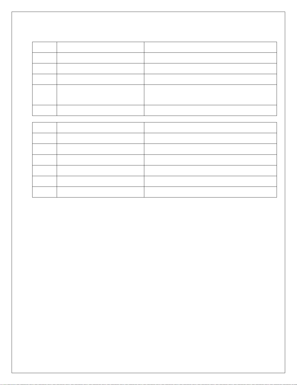
OP3 Time & Date
3.1
3.2
3.3
3.4
3.5
OP4
OP5
OP6
6.1
---, 24H, 12A, 12P Skip time, 24 hour, 12 hour am, 12 hour pm
T1 Set time: hh mm ss
dA Set date: mm dd yy
S.no, no, Let
Off, Un, Ab, On Print under, above or on the same line
Weigh – In / Weigh - Out See page 19
10 Point Linearity On, Off see page 9
Totalizer
Off, On Enable Totalizer (operates with Batch or Print)
Month print selection, short numerical
(mm/dd/yy), number 01 thru 12, month spelled
out
6.2
Option 6 Totalizer: Operates with “print” function in normal mode or batch mode.
In normal mode, current value is added to the totalizer with each “Print” command. The
reset band is used to inhibit a double add when not in Batch Mode.
View the Total with the “2” key and during the display (AC..XXXX), the “Print” key is
used to print the total, the “Ent” key returns to weigh mode.
The “Clear” key is used to clear the totalizer by first changing the message from
“Clr.ACC…no” to “Clr.ACC…yes” with the “Units” key and “Ent” to complete. A
“Cleared” message is provided for conformation.
Note: Totalizer works with port 1 only and the “Print” key is disabled when Batch Mode
and Totalizer are both enabled.
Off, 1……50 Totalizer reset band
19
Page 21
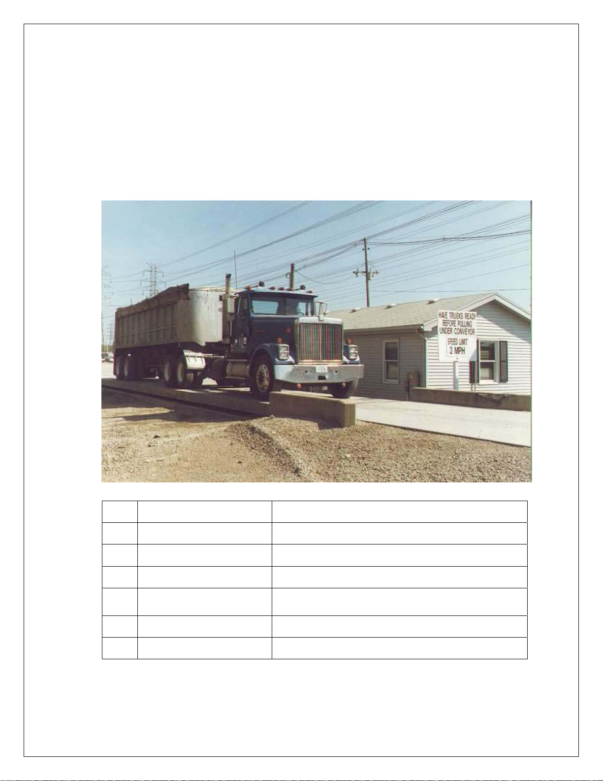
OPTION 4: Weigh – In / Weigh – Out
Truck Scale Application: Provides storage up to 300 transactions with six digit
Identification. Operates in “Gross” only.
This mode provides a system for single scale applications to determine net weight by
storing incoming weight and completing the transaction with out going weight.
Options are provided to maintain “store” Tares or to manually input tare weight.
4.1
4.2
4.3
4.4
4.5
4.6
4.7
Note: Print format based on smart serial setup or unlabeled default.
Off, On Turn on Weigh–in / Weigh-out
No, Yes Delete record after weigh–out transaction
No, Yes Enable manual tare
1, 2 Select print port 1 or 2
8n1, 7e1, 7o1
1200…..9600 BAUD rate selection
Off, 1, 2, 3 Line feed delay
Data setup, 8 bit no parity one stop, 7 bit even
one stop, 7 bit odd one stop
20
Page 22

Full Truck IN
Truck enters scale full, scale indicates “Stable”.
Operator inserts ticket and pushes “Print” key.
Display responds with “Id no” prompt.
Operator enters truck “ID Number”, up to 6 – digits.
Operator pushes “Ent” key.
Printer prints: Time/Date (optional)
(xxxxxx) ID. NO.
(xxxxxx) lb GR
Truck goes to empty load.
Empty truck returns to scale, scale indicates “Stable”.
Operator pushes “Print” key and “Id no” prompt appears.
Operator enters same ID Number as previously printed.
Operator pushes “Ent” key.
Printer prints complete transaction:
Time/Date (optional)
(xxxxxx) ID. NO.
(xxxxxx) lb GR Recalled
(xxxxxx) lb TR
(xxxxxx) lb NT
Empty Truck IN
Truck enters scale empty, scale indicates “Stable”.
Operator inserts ticket and pushes “Print” key.
Display responds with “Id no” prompt.
Operator enters truck “ID Number”, up to 6 – digits.
Operator pushes “Ent” key.
Printer prints: Time/Date (optional)
(xxxxxx) ID. NO.
(xxxxxx) lb GR
Truck goes to fill load.
Full truck returns to scale, scale indicates “Stable”.
Operator pushes “Print” key and “Id no” prompt appears.
Operator enters same ID Number as previously printed.
Operator pushes “Ent” key.
21
Page 23

Printer prints complete transaction:
Time/Date (optional)
(xxxxxx) ID. NO.
(xxxxxx) lb GR
(xxxxxx) lb TR Recalled
(xxxxxx) lb NT
Fixed Tare
Truck enters scale full, scale indicates “Stable”.
Operator inserts ticket and pushes “Print” key.
Display responds with “Id no” prompt.
Operator enters truck “ID Number”, up to 6 – digits.
Operator pushes “Tare” key.
Display responds with “Tare” prompt.
Operator enters tare weight.
Operator pushes the “Ent” key.
Printer prints: Time/Date (optional)
(xxxxxx) ID. NO.
(xxxxxx) lb GR
(xxxxxx) lb TR (Recalled*) Keyed
(xxxxxx) lb NT
*”Recalled” added if from stored Tare.
Transaction Buffer: Select / Print / Clear / Clear All
Select ID: With “ID” displayed, user can select a stored ID by pressing “Set”
(up) or “Start/Stop” (down) to scroll through the buffer.
Print Buffer: Pushing Gross/Net with ID displayed will cause output of the
complete buffer ( ID with Tare).
Clear ID: Pushing clear with ID displayed will clear that ID and step to the
next.
Clear ALL: With “ID”, holding the clear switch will prompt “Rec.Clr” and using
unit to switch to “yes” and enter will clear entire buffer.
22
Page 24

Option 7: SMART SERIAL I/O
The SMART SERIAL I/O option now offers a wide degree of flexibility for an operator to
customize the serial output format for individual system requirements. The custom print
currently supports:
Specifying starting and terminating characters (stx, cr, lf, etc.).
Adding printer control characters.
Custom headers, titles, etc..
Customized parameters such as "GROSS WEIGHT" instead of "GR".
Custom insertion of special parameters such as time/date and identification no.
Truck mode custom printing.
Custom continuous serial protocol.
Custom 'P' print out in duplex mode.
FEATURES:
* Eight (8) custom print files automatically assigned.
* Eight (8) macro files for easy setup of headers, titles, etc. .
* Capability to upload and download the custom print files to a host computer.
* Maximum file length is 30 characters and/or parameters. Maximum number of
characters in an output string is (250).
Note! Custom print does not support RS485 protocol
STANDARD SERIAL CONFIGURATION:
The SMART SERIAL I/O Option allows standard serial output ports to be modified and
imported into the serial output data stream.
The table below lists configuration parameters and Option modes that are associated
with the customized print.
CUSTOM PROTOCOL FILE SELECTION:
The selection of the associated custom print file is performed automatically by serial port
and the data mode (GROSS, NET, TOTAL RECALL, or SPECIAL) that the instrument is
currently in at the time of a print. In other words, if Ports 1 & 2 were selected for demand
print (dE) and the instrument was in the "GROSS" mode at the time of a print request of the
data, the serial output for Port 1 would use the contents of file 1 (7.1) and the contents of
file 5 (7.5) for Port 2.
23
Page 25
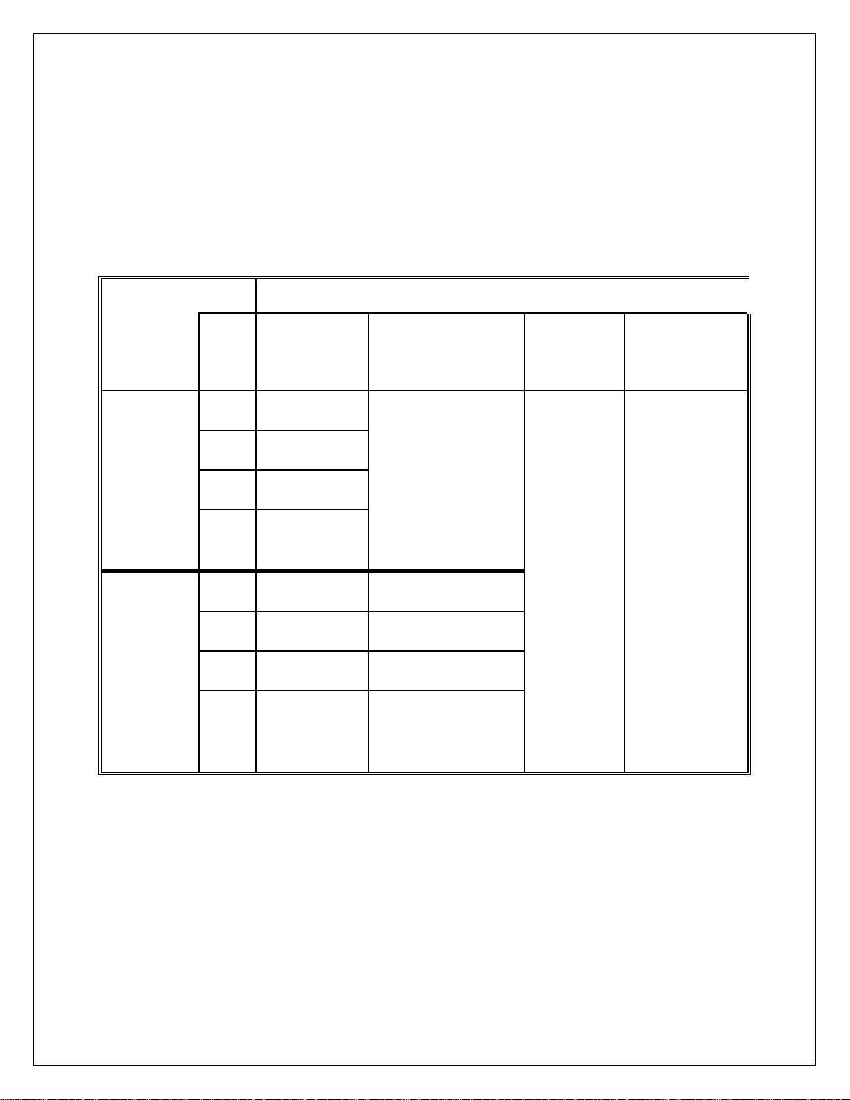
GENERAL:
The selections under Option 7 may be divided into three main functional groups; the first 8
files (7.1 to 7.8), each of which can store up to 30 ASCII and/or parameter codes, are files
pertaining to the actual customization of serial output data and are themselves further
subdivided into Port 1 files (7.1 to 7.4) and Port 2 files (7.5 to 7.8), the second functional
group pertains to the 8 MACRO files (7.9 to 7.16) that may be entered into the primary files
(7.1 to 7.8) by their associated parameter codes 600 to 607 (7.9 = parameter code 600
etc.), each of these files can also store up to 30 ASCII and/or parameter codes.
FILE
CUSTOMIZING
NORMAL
MODE
TRUCK
MODE
MACROS
(8)
MACRO
Parameter
codes
PORT 1
PORT 2
7.1
7.2
7.3
7.4
7.5
7.6
7.7
7.8
Gross data
Net data
Total data
Special
(for future use)
Gross data Truck Entry
Net data
Total data
Special
Truck Mode
Output Port is
selected under
option 4, Port 1
selection mirrors
Port 2 below.
7.9 600
7.10 601
7.11 602
7.12 603
7.13 604
Truck Out Empty 7.14 605
Truck Out Full
7.15 606
Truck Fixed Tare 7.16 607
(for future
use)
Notes:
If Option 7 is enabled ("on") but a designated file is set to off then that print mode will print
its default format (eg. file 7.1 off - the GROSS data from Port 1 is sent out in its default
format).
24
Page 26

MACRO FILES (7.9 TO 7.16):
There are eight (8) macro files that can be accessed in any of the prime Print Files 1 - 8
(7.1 to 7.8) using the "600" series codes. Each macro file holds up to 30 ASCII characters
and/or parameter codes.
Example: A header stating the company's name Scrap inc. is desired when Port 1 outputs
GROSS mode weight data.
Printout = Scrap inc.
30000 LB GR 05/13/2005 12:30am
PRINT FILE 1 (7.1 - Port 1 "GROSS" mode data)
LINE # CODE CODE definition
01 002 STX (start of text)
02 600 * macro file #1 (7.9)
03 200 gross wt. with "LB/KG GR"
04 032 SP (space)
05 601 *macro file #2 (7.10)
06 013 CR (carriage return)
07 010 LF (line feed)
08 999 END OF FILE
CODE 600 (MACRO FILE 7.9) CODE 601 (MACRO FILE 7.10)
LINE # CODE CODE definition LINE # CODE Definition
01 083 S character 01 402 Date
02 099 c character 02 032 SP
03 114 r character 03 401 Time
04 097 a character 04 999 END
05 112 p character
06 032 SP (space)
07 105 i character
08 110 n character
09 099 c character
10 046 . (period)
11 013 CR (carriage return)
12 010 LF (line feed)
13 999 END OF FILE
25
Page 27
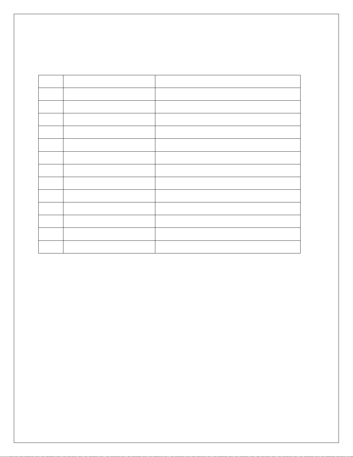
CREATING AND EDITING FILES: OPTION 7 CONFIGURATION
7.0
7.X
7.1
Off, On Enables smart serial
Off, On Enables each print buffer 7.1…..7.16
Key Description
SET Access buffer 7.1 and exit when done
0-9 Use numeric keys to enter code 0-999
ENT Enter code
CLEAR Clear the code
START/STOP Insert code
TARE RECALL Clear entire (current) buffer
GROSS/NET Steps to next buffer position
TARE Go to first buffer position
ZERO Go to last buffer position
26
Page 28

IMPORTANT! All files must be terminated with code 999
CUSTOM PRINT FILES REMOTE READ AND WRITE
SSC (Smart Serial Codes) command is provided to read or write buffer data 7.1…7.16.
Example:
Read
SSC<CR>
SSC 1 2 600 200 32 601 13 10 999
SSC 9 83 99 114 97 112 32 105 110 99 46 13 10 999
SSC 10 402 32 401 999
Write
SSC<sp><X><yyy><yyy><cr> Where X = buffer 1…16 (7.1…7.16), yyy = code
With a txt editor (such as Windows Notepad) and the serial loader program, buffers can
be created and edited.
Text strings can also be entered directly surrounded by quotes:
SSC 9 “Scrap inc.” 702 999
Note: the 702 command CR/LF (13 10).
27
Page 29
ASCII CONTROL CODE CHART 1
CONTROL
CHAR
CODE
CONTROL
CHAR
CODE
SYMBOLS
CHAR
CODE
NUMBERS
CHAR
CODE
NUL
SOH
STX
ETX
EOT
ENQ
ACK
BEL
BS
HT
LF
VT
FF
CR
SO
SI
000
001
002
003
004
005
006
007
008
009
010
011
012
013
014
015
DLE
DC1
DC2
DC3
DC4
NAK
SYN
ETB
CAN
SUB
ESC
EM
FS
GS
RS
US
016
017
018
019
020
021
022
023
024
025
026
027
028
029
030
031
SP
!
"
#
$
%
&
'
(
)
*
+
,
-
.
/
032
033
034
035
036
037
038
039
040
041
042
043
044
045
046
047
0
1
2
3
4
5
6
7
8
9
:
;
<
=
>
?
048
049
050
051
052
053
054
055
056
057
058
059
060
061
062
063
28
Page 30
ASCII CONTROL CODE CHART 2
UPPER CASE
CHAR
@
A
B
C
D
E
F
G
H
I
J
K
L
M
N
O
CODE
064
065
066
067
068
069
070
071
072
073
074
075
076
077
078
079
UPPER CASE
CHAR
P
Q
R
S
T
U
V
W
X
Y
Z
[
\
]
^
_
CODE
080
081
082
083
084
085
086
087
088
089
090
091
092
093
094
095
LOWER CASE
CHAR
`
a
b
c
d
e
f
g
h
i
j
k
l
m
n
o
CODE
096
097
098
099
100
101
102
103
104
105
106
107
108
109
110
111
LOWER CASE
CHAR
p
q
r
s
t
u
v
w
x
y
z
{
|
}
~
CODE
112
113
114
115
116
117
118
119
120
121
122
123
124
125
126
29
Page 31
PARAMETER CONTROL CODE CHART
CODE
DESCRIPTION CODE DESCRIPTION
200
201
202
203
210
211
212
213
220
221
222
223
230
231
232
233
GROSS WT & 'LB/KG GR'
GROSS WT & 'LG/KG'
GROSS WT
GROSS WT(no 0 blanking)
NET WT & 'LB/KG NT'
NET WT & 'LN/KN'
NET WT
NET WT (no 0 blanking)
TARE WT & 'LB/KG TR'
TARE WT & 'LT/KT'
TARE WT
TARE WT(no 0 blanking)
TOTAL WT & lb/kg
TOTAL WT & LA/KA
TOTAL WT ONLY
TATAL WT (no “0” blanking)
240 TRUCK GR0SS 'LB/KG GR'
241 TRUCK GROSS ONLY
242 TRUCK TARE 'LB/KG TR'
243 TRUCK TARE ONLY
244 TRUCK NET 'LB/KG NT'
245 TRUCK NET ONLY
300 STATUS CHARACTER
400 TIME & DATE PER SETUP
401 TIME PER SETUP
402 DATE PER SETUP
500 IDENT NO. & 'ID. NO.'
501 IDENT NO. ONLY
510 TICKET NO & COUNT
511 COUNT ONLY
702 CR/LF
30
Page 32
CUSTOM SERIAL ENTRY WORKSHEET
LINE COD
E
1
2
3
4
5
6
7
8
9
10
11
12
13
14
15
DESCRIPTION
LINE COD
16
17
18
19
20
21
22
23
24
25
26
27
28
29
30
E
DESCRIPTION
Option 8: AC/DC operation
8.1
8.2
Off, On Enables battery charger
Off, 5, 15, 30, 90, 120 Auto shutoff in minutes, timer resets with motion
31
Page 33
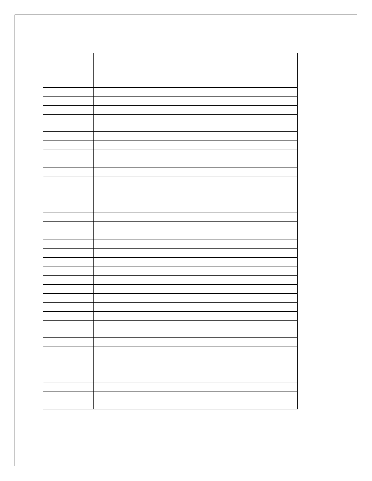
DISPLAY MESSAGES
MESSAGE DESCRIPTION
DAC
IIC.ERR
RST
ON
AUTO
ERR6.x
-232-
UPDATE
LO.BATT
D BATT
ULULUL
OLOLOL
------
7x00
Err 10
Err 13
ADC.Err
CHECK
rC.xxxx
Err.80
Err.81
-CAL-
Err.OFF
RTC.RST
RST ID
AC OK
E-1234
Err 40
Err 31
Err 30
PC Err
D/A card detected - Displayed under the check function.
IIC short - Power-up hardware failure indication.
EEPROM is reset by EER command - Power-up message
Displayed on power-up when the DC power push-button is
pressed.
EEPROM is reset - Power-up message
Key-pad key is stuck.
Serial calibration/setup is active.
Enhancement calculation in progress.
Low battery
Dead battery
Under-load (-400 graduations under dead-zero)
Over-load (+9 graduations or 105% from dead-zero
reference)
A/D acquisition is in progress.
Instrument mode selection.
Number > 999999
Number < -99999
A/D hardware failure (channel one only).
Check mode accessed.
Lower four-digits of the ROM check-sum.
Serial command data error.
Unknown serial command.
Remote calibration
Hardware failure of the D.C. power on/off circuitry.
The clock is reset to 01:01:04 12:00:00am.
The ID EEPROM has been reset since it was detected as
corrupt.
Access code entered has been accepted.
EEPROM set 1,2,3, and/or 4 have been fixed.
Positive or negative signal overload (check sense
connections).
Bad tare entry
Push to Zero out of range
Piece Weight Entry is out of range
32
Page 34
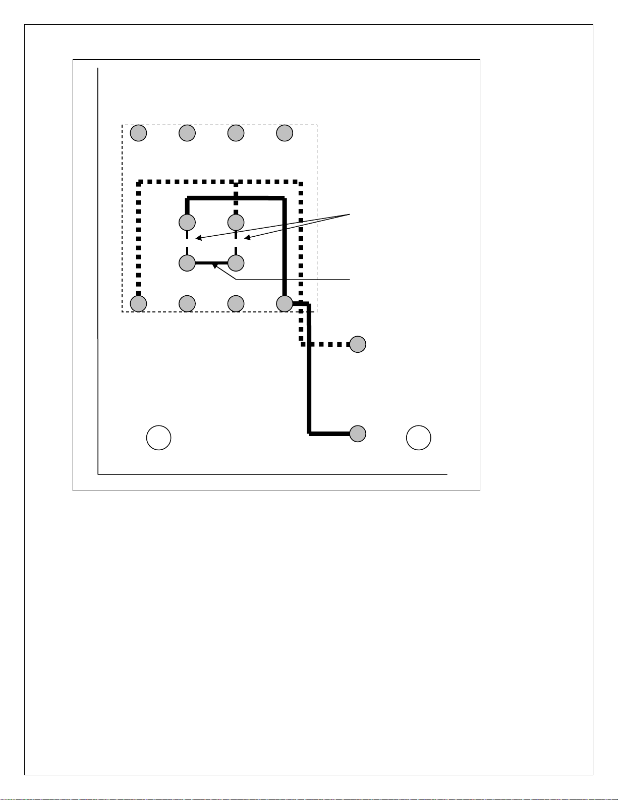
115 to 220 VAC Conversion : EW1000 Bottom Side
CUT CLAD
2-Places
ADD Jumper
33
Page 35

WARRANTY/DISCLAIMER
OMEGA ENGINEERING, INC. warrants this unit to be free of defects in materials and workmanship for a
period of 13 months from date of purchase. OMEGA’s WARRANTY adds an additional one (1) month
grace period to the normal one (1) year product warranty to cover handling and shipping time. This
ensures that OMEGA’s customers receive maximum coverage on each product.
If the unit malfunctions, it must be returned to the factory for evaluation. OMEGA’s Customer Service
Department will issue an Authorized Return (AR) number immediately upon phone or written request.
Upon examination by OMEGA, if the unit is found to be defective, it will be repaired or replaced at no
charge. OMEGA’s WARRANTY does not apply to defects resulting from any action of the purchaser,
including but not limited to mishandling, improper interfacing, operation outside of design limits,
improper repair, or unauthorized modification. This WARRANTY is VOID if the unit shows evidence of
having been tampered with or shows evidence of having been damaged as a result of excessive corrosion;
or current, heat, moisture or vibration; improper specification; misapplication; misuse or other operating
conditions outside of OMEGA’s control. Components which wear are not warranted, including but not
limited to contact points, fuses, and triacs.
OMEGA is pleased to offer suggestions on the use of its various products. However,
OMEGA neither assumes responsibility for any omissions or errors nor assumes liability for any
damages that result from the use of its products in accordance with information provided by
OMEGA, either verbal or written. OMEGA warrants only that the parts manufactured by it will be
as specified and free of defects. OMEGA MAKES NO OTHER WARRANTIES OR
REPRESENTATIONS OF ANY KIND WHATSOEVER, EXPRESS OR IMPLIED, EXCEPT THAT OF TITLE,
AND ALL IMPLIED WARRANTIES INCLUDING ANY WARRANTY OF MERCHANTABILITY AND
FITNESS FOR A PARTICULAR PURPOSE ARE HEREBY DISCLAIMED. LIMITATION OF
LIABILITY: The remedies of purchaser set forth herein are exclusive, and the total liability of
OMEGA with respect to this order, whether based on contract, warranty, negligence,
indemnification, strict liability or otherwise, shall not exceed the purchase price of the
component upon which liability is based. In no event shall OMEGA be liable for
consequential, incidental or special damages.
CONDITIONS: Equipment sold by OMEGA is not intended to be used, nor shall it be used: (1) as a “Basic
Component” under 10 CFR 21 (NRC), used in or with any nuclear installation or activity; or (2) in medical
applications or used on humans. Should any Product(s) be used in or with any nuclear installation or
activity, medical application, used on humans, or misused in any way, OMEGA assumes no responsibility
as set forth in our basic WARRANTY/ DISCLAIMER language, and, additionally, purchaser will indemnify
OMEGA and hold OMEGA harmless from any liability or damage whatsoever arising out of the use of the
Product(s) in such a manner.
RETURN REQUESTS/INQUIRIES
Direct all warranty and repair requests/inquiries to the OMEGA Customer Service Department. BEFORE
RETURNING ANY PRODUCT(S) TO OMEGA, PURCHASER MUST OBTAIN AN AUTHORIZED RETURN
(AR) NUMBER FROM OMEGA’S CUSTOMER SERVICE DEPARTMENT (IN ORDER TO AVOID
PROCESSING DELAYS). The assigned AR number should then be marked on the outside of the return
package and on any correspondence.
The purchaser is responsible for shipping charges, freight, insurance and proper packaging to prevent
breakage in transit.
FOR W
ARRANTY RETURNS, please have the
following information available BEFORE
contacting OMEGA:
1. Purchase Order number under which the product
was PURCHASED,
2. Model and serial number of the product under
warranty, and
3. Repair instructions and/or specific problems
relative to the product.
FOR NON-WARRANTY REPAIRS,
consult OMEGA
for current repair charges. Have the following
information available BEFORE contacting OMEGA:
1. Purchase Order number to cover the COST
of the repair,
2. Model and serial number of the product, and
3. Repair instructions and/or specific problems
relative to the product.
OMEGA’s policy is to make running changes, not model changes, whenever an improvement is possible. This affords
our customers the latest in technology and engineering.
OMEGA is a registered trademark of OMEGA ENGINEERING, INC.
© Copyright 2004 OMEGA ENGINEERING, INC. All rights reserved. This document may not be copied, photocopied,
reproduced, translated, or reduced to any electronic medium or machine-readable form, in whole or in part, without the
prior written consent of OMEGA ENGINEERING, INC.
Page 36

M-4374/1006
Where Do I Find Everything I Need for
Process Measurement and Contr ol?
OMEGA…Of Course!
Shop online at www.omega.com
TEMPERA TURE
Thermocouple, RTD & Thermistor Probes, Connectors, Panels & Assemblies
Wire: Thermocouple, RTD & Thermistor
Calibrators & Ice Point References
Recorders, Controllers & Process Monitors
Infrared Pyrometers
PRESSURE, STRAIN AND FORCE
Transducers & Strain Gages
Load Cells & Pressure Gages
Displacement Transducers
Instrumentation & Accessories
FLOW/LEVEL
Rotameters, Gas Mass Flowmeters & Flow Computers
Air Velocity Indicators
Turbine/Paddlewheel Systems
Totalizers & Batch Controllers
pH/CONDUCTIVITY
pH Electrodes, Testers & Accessories
Benchtop/Laboratory Meters
Controllers, Calibrators, Simulators & Pumps
Industrial pH & Conductivity Equipment
DA TA ACQUISITION
Data Acquisition & Engineering Software
Communications-Based Acquisition Systems
Plug-in Cards for Apple, IBM & Compatibles
Datalogging Systems
Recorders, Printers & Plotters
HEA TERS
Heating Cable
Cartridge & Strip Heaters
Immersion & Band Heaters
Flexible Heaters
Laboratory Heaters
ENVIRONMENT AL
MONITORING AND CONTROL
Metering & Control Instrumentation
Refractometers
Pumps & Tubing
Air, Soil & Water Monitors
Industrial Water & Wastewater Treatment
pH, Conductivity & Dissolved Oxygen Instruments
 Loading...