

Page 1
WE35-DHD00-T1
By Dwye
r
Bulletin V-WE35
Series WE35 3-Way NPT Brass Ball Valve
Specications - Installation and Operating Instructions
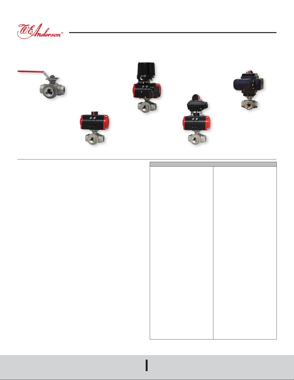
WE35-DDA02-T1-AA01
WE35-DDA02-L1 WE35-DDA02-T3-NN05
The SERIES WE35 incorporates a full port 3-way brass ball valve for great ow rates
with minimal pressure drop. The valve features a blowout proof stem for added safety,
reinforced PTFE seats and seals for longer life, and a brass ball for better performance.
Actuators are direct mounted creating a compact assembly for tight spaces.
The Series WE35 can be congured with either an electric or pneumatic actuator.
Electric actuators are available in weatherproof or explosion-proof, a variety of supply
voltages, and two-position or modulating control. Two-position actuators use the
supply voltage to drive the valve open or closed, while the modulating actuator accepts
a 4 to 20 mA input for valve positioning. Actuators feature thermal overload protection
and permanently lubricated gear train.
The pneumatic double acting actuator uses an air supply to drive the valve open
and closed. The actuator has two supply ports, with one driving the valve open and
the other driving the valve closed. Spring return pneumatic actuators use the air
supply to open the valve and internally loaded springs return the valve to the closed
position. Also available is the SN solenoid valve to electrically switch the air supply
pressure between the air supply ports for opening and closing the valve. Actuators
are constructed of anodized and epoxy coated aluminum for years of corrosion free
service.
SPECIFICATIONS
VALV E
Service: Compatible liquids and gases.
Body: 3-way.
Line Sizes: 1/2 to 2˝.
End Connections: Female NPT.
Pressure Limits: 600 psi (41 bar) WOG.
Wetted Materials: Body, ball, and stem:
Brass; Seat, seal, and packing: PTFE.
Temperature Limits: -20 to 425°F (-30
to 220°C).
Other Materials: O-ring: NBR; Handle,
stem nut, ferrule: SS; Handle Sleeve:
Vinyl; Body and cap: Nickle plated.
ACTUATORS
Pneumatic “DA” and “SR” Series
Type: DA series is a double acting and
SR series is a spring return (rack and
pinion).
Normal Supply Pressure: DA: 40 to 115
psi (2.7 to 7.9 bar); SR: 80 psi (5.5 bar).
Maximum Supply Pressure: 120 psi
(8.6 bar).
Air Connections: DA02 to DA03: 1/4˝
female NPT; SR02 to SR04: 1/4” female
NPT.
Housing Material: Anodized aluminum
body and epoxy coated aluminum end
caps.
Temperature Limits: -40 to 176°F (-40
to 80°C).
Accessory Mounting: NAMUR
standard.
WE35-DTD01-T3-A
Electric “TD” and “MD” Series
Power Requirements: 110 VAC, 220
VAC, 24 VAC, or 24 VDC (MD models
not available in 24 VDC).
Power Consumption: See instruction
manual.
Cycle Time (per 90°): TD01: 4 s; MD01:
10 s; TD02: 20 s).
Duty Rating: 85%.
Enclosure Rating: NEMA 4X (IP67).
Housing Material: Powder coated
aluminum.
Temperature Limits: -22 to 140°F (-30
to 60°C).
Electrical Connection: 1/2˝ female NPT.
Modulating Input: 4 to 20 mA.
Standard Features: Manual override,
position indicator, and TD models come
with two limit switches.
Electric “TI” and “MI” Series
Power Requirements: 110 VAC, 220
VAC, 24 VAC, 24 VDC.
Power Consumption: See instruction
manual.
Cycle Time (per 90°): See instruction
manual.
Duty Rating: See instruction manual.
Enclosure Rating: NEMA 7, designed
to meet hazardous locations: Class I,
Group C & D; Class II, Group E, F & G;
Division I & II.
Housing Material: Powder coated
aluminum.
Temperature Limits: -40 to 140°F (-40
to 60°C).
Electrical Connection: 1/2˝ female NPT.
Modulating Input: 4 to 20 mA.
Standard Features: Position indicator
and two limit switches.
W.E. ANDERSON
A DIVISION OF
DWYER INSTRUMENTS, INC.
P.O. BOX 373 • MICHIGAN CITY, INDIANA 46360, U.S.A.
Phone: 219/879-8000
Fax: 219/872-9057
www.dwyer-inst.com
e-mail: [email protected]
Page 2
L
Ra
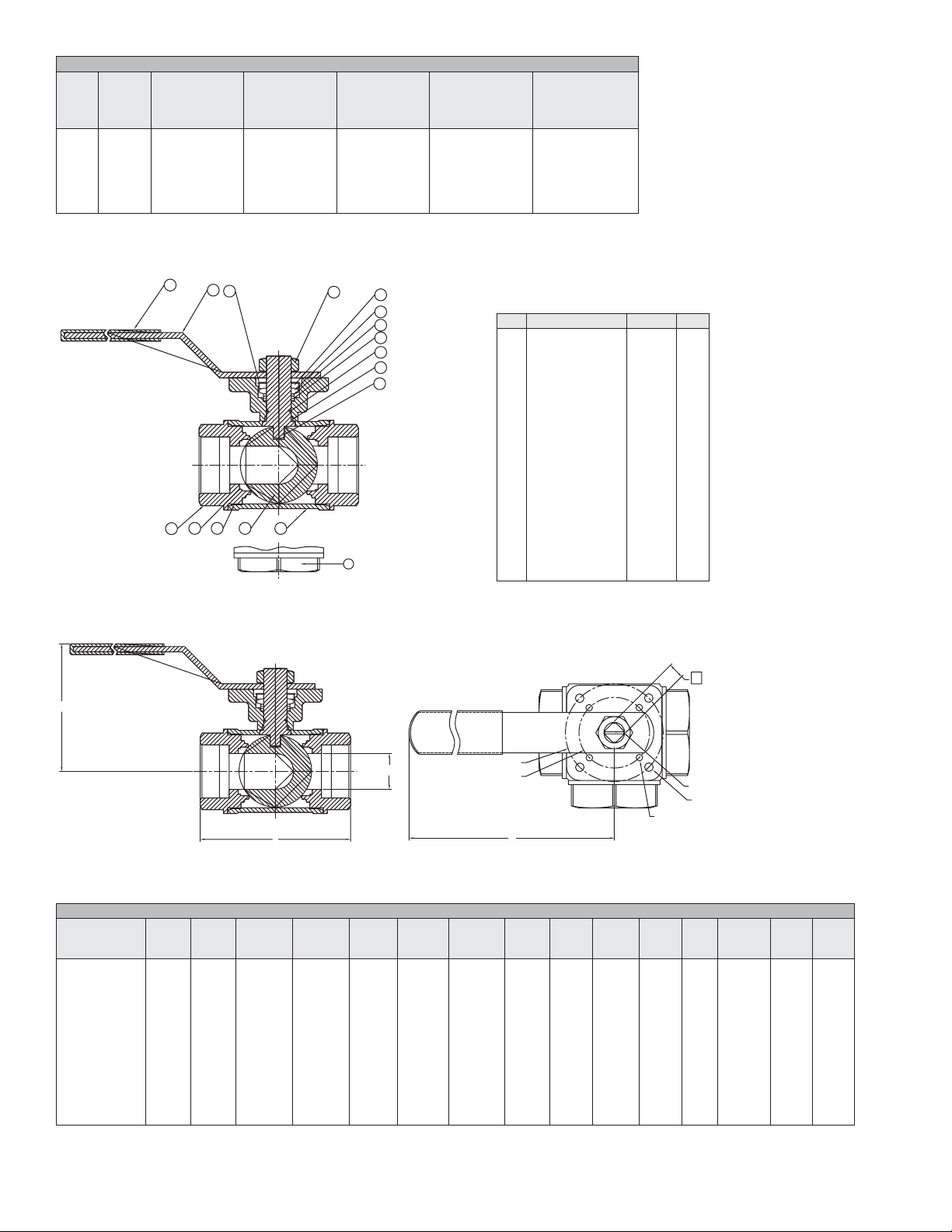
MODEL CHART
Cv
Size
(gal/min)
1/2˝
13
3/4˝
37
1˝
49
1-1/14˝
59
1-1/2˝
100
2˝
115
VALVE BILL OF MATERIALS
Popular
Hand Operated
Model
WE35-CHD00-T1
WE35-DHD00-T1
WE35-EHD00-T1
WE35-FHD00-T1
WE35-GHD00-T1
WE35-HHD00-T1
15
2
435
14
16
Popular
Double Acting
Pneumatic
Model
WE35-CDA02-T2
WE35-DDA02-T2
WE35-EDA02-T2
WE35-FDA03-T2
WE35-GDA03-T2
WE35-HDA03-T2
1
Popular
Spring Return
Pneumatic
Model
WE35-CSR02-T2
WE35-DSR03-T2
WE35-ESR03-T2
WE35-FSR03-T2
WE35-GSR03-T2
WE35-HSR04-T2
13
12
11
10
9
8
7
6
18
Popular NEMA 4X
Two Position
Electric
(110 VAC) Model
WE35-CTD01-T2-A
WE35-DTD01-T2-A
WE35-ETD01-T2-A
WE35-FTD01-T2-A
WE35-GTD01-T2-A
WE35-HTD02-T2-A
Item Description Material Qty
1
2
3
4
5
6
7
8
9
10
11
12
13
14
15
16
17
18
Popular NEMA 4X
Modulating
Electric
(110 VAC) Model
WE35-CMD01-T2-A
WE35-DMD01-T2-A
WE35-EMD01-T2-A
WE35-FMD01-T2-A
WE35-GMD01-T2-A
WE35-HMD01-T2-A
Body
Cap-A
Ball
Ball seat
Joint gasket
Stem
Thrust washer
O-ring
Stem packing
Gasket
V sealing
Lock nut
Stem nut
Handle
Handle cover
Ferrule
Stopper, bolt & Nut
Cap-B
Brass
Brass
Brass
PTFE
PTFE
Brass
NBR
NBR
PTFE
PTFE
AISI 304
AISI 304
AISI 304
AISI 304
PVC
AISI 304
AISI 304
Brass
1
2
1
2
1
1
1
1
1-2
1
1
1
1
1
1
1
1
1
VALVE DIMENSIONAL DRAWING
H
MODEL CHART
Model Size
WE35-CHD00-T1
WE35-DHD00-T1
WE35-EHD00-T1
WE35-FHD00-T1
WE35-GHD00-T1
WE35-HHD00-T1
Ø A
in (mm)Lin (mm)Win (mm)Hin (mm)
13/32˝
1/2˝
(10)
1/2˝
3/4˝
(13)
1˝
3/4˝
(19)
1-1/4˝
63/64˝
(25)
1-1/2˝
1-17/64˝
(32)
2˝
1-1/2˝
(38)
2-61/64˝
(75)
3-23/64˝
(85)
3-15/16˝
(100)
4-39/64˝
(117)
5-19/32˝
(142)
6-9/64˝
(156)
5-33/64˝
(140)
6-5/16˝
(160)
6-5/16˝
(160)
7-9/32˝
(185)
7-9/32˝
(185)
7-9/32˝
(185)
1-37/64˝
(40)
1-49/64˝
(45)
1-57/64˝
(48)
2-11/64˝
(55)
2-13/32˝
(61)
2-3/4˝
(70)
ØA
Ø D1
in (mm)
-
1-31/32˝
(50)
1-31/32˝
(50)
2-49/64˝
(70)
2-49/64˝
(70)
2-49/64˝
(70)
S
ØD1
ØD2
W
Ø D2
in (mm) ISOØSin (mm)Rain (mm)Rbin (mm) PORT M1
1-27/64˝
(36)
-
-
1-31/32˝
(50)
1-31/32˝
(50)
1-31/32˝
(50)
F03
F05
F05
F07/F05
F07/F05
F07/F05
23/64˝
(9)
7/16˝
(11)
7/16˝
(11)
9/16˝
(14)
9/16˝
(14)
9/16˝
(14)
-
R1/8˝
(R3)
R1/8˝
(R3)
R11/64˝
(R4)
R11/64˝
(R4)
R11/64˝
(R4)
R7/64˝
(R2.5)
-
-
R1/8˝
(R3)
R1/8˝
(R3)
R1/8˝
(R3)
M1
Rb
M12x1.5
L
M14x1.5
L
M14x1.5
L
M18x1.5
L
M18x1.5
L
M18x1.5
L
Torque
(in-lb)
62
89
124
142
142
222
CV
(gal/
min)
13
37
49
59
100
115
2
Page 3
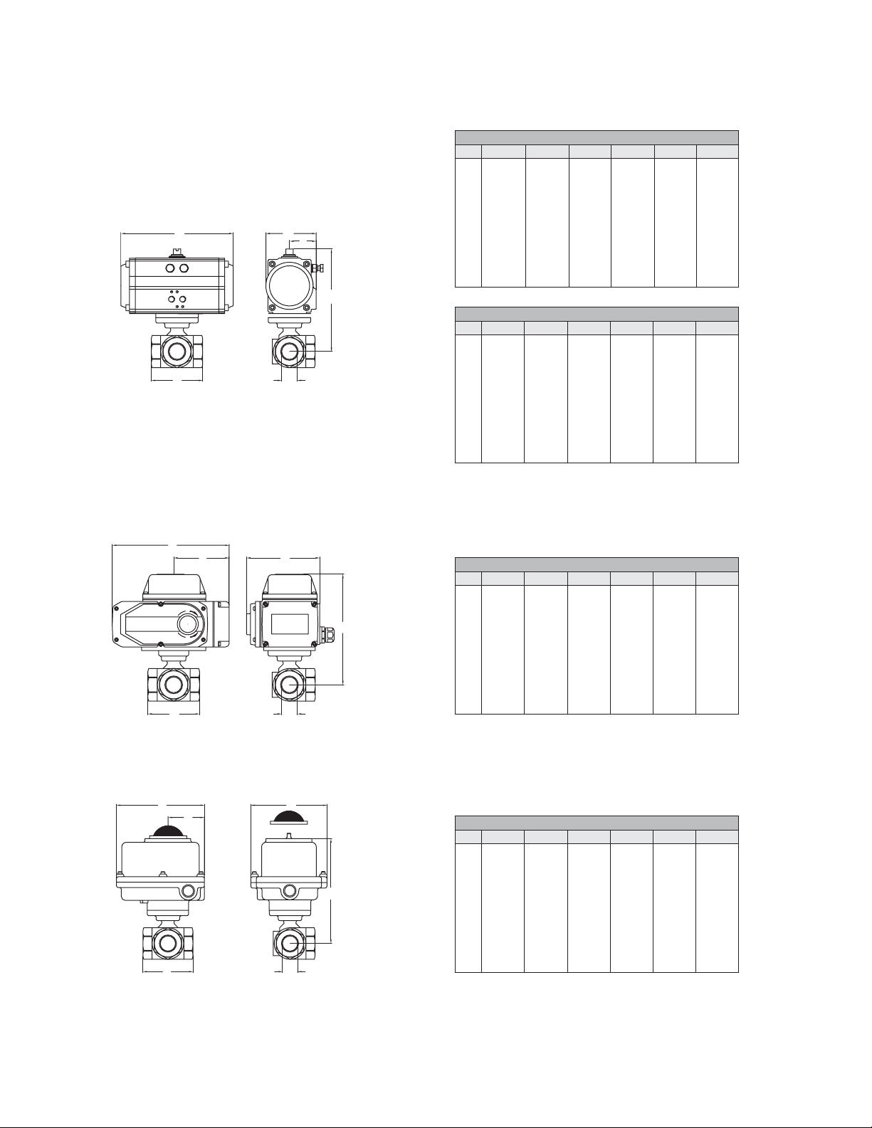
AUTOMATED VALVE DRAWINGS
B
D
NPT
W/ PNEUMATIC ACTUATOR
D
B
W/ ELECTRIC ACTUATOR
D
B
NPT
W/ EXPLOSION-PROOF ELECTRIC ACTUATOR
E
DOUBLE ACTING PNEUMATIC ACTUATOR
NPT 1/2˝ 3/4˝ 1˝ 1-1/4˝ 1-1/2˝ 2˝
5-1/4˝
B
133 mm
2-3/4˝
C
71 mm
D
3˝
C
F
76 mm
E
5-3/4˝
145 mm
F
1-5/8˝
41 mm
5-3/8˝
136 mm
2-3/4˝
71 mm
3-3/8˝
86 mm
5-3/4˝
145 mm
1-5/8˝
41 mm
6-3/8˝
162 mm
3-1/4˝
82 mm
3-7/8˝
99 mm
6-5/8˝
169 mm
1-3/4˝
46 mm
6-5/8˝
167 mm
3-1/4˝
82 mm
4-5/8˝
117 mm
6-5/8˝
169 mm
1-3/4˝
46 mm
7-3/4˝
196 mm
3-3/4˝
94 mm
4-7/8˝
124 mm
7-7/8˝
201 mm
2˝
52 mm
8˝
205 mm
3-3/4˝
94 mm
5-7/8˝
148 mm
7-7/8˝
201 mm
2˝
52 mm
SPRING RETURN PNEUMATIC ACTUATOR
NPT 1/2˝ 3/4˝ 1˝ 1-1/4˝ 1-1/2˝ 2˝
5-1/4˝
B
133 mm
2-3/4˝
C
71 mm
D
3˝
76 mm
E
5-3/4˝
145 mm
F
1-5/8˝
41 mm
5-3/8˝
136 mm
2-3/4˝
71 mm
3-3/8˝
86 mm
5-3/4˝
145 mm
1-3/4˝
46 mm
6-7/8˝
174 mm
3-3/4˝
94 mm
3-7/8˝
99 mm
7-7/8˝
201 mm
2˝
52 mm
7-3/8˝
187 mm
4˝
101 mm
4-5/8˝
117 mm
10-1/2˝
268 mm
2-1/8˝
55 mm
8-1/2˝
216 mm
4-1/4˝
109 mm
4-7/8˝
124 mm
9-1/2˝
242 mm
2-1/4˝
58 mm
9-3/8˝
237 mm
4-3/4˝
122 mm
5-7/8˝
148 mm
10-7/8˝
275 mm
2-1/2˝
64 mm
E
S
O
E
F
OPEN
F
C
ELECTRIC ACTUATOR
NPT 1/2˝ 3/4˝ 1˝ 1-1/4˝ 1-1/2˝ 2˝
6-1/2˝
NPT
B
167 mm
5-1/4˝
C
133 mm
D
3˝
76 mm
E
6-1/8˝
154 mm
F
2-3/4˝
68 mm
10-1/8˝
257 mm
9-3/8˝
239 mm
3-3/8˝
86 mm
8-1/2˝
217 mm
5˝
126 mm
8-1/2˝
216 mm
9-3/8˝
239 mm
3-7/8˝
99 mm
8-1/2˝
217 mm
5˝
126 mm
11-3/8˝
290 mm
7-1/8˝
180 mm
4-5/8˝
117 mm
8-1/2˝
216 mm
5-3/8˝
136 mm
10-1/8˝
256 mm
7-1/8˝
180 mm
4-7/8˝
124 mm
8-1/2˝
216 mm
5-3/8˝
136 mm
10-3/8˝
264 mm
7-1/8˝
180 mm
5-7/8˝
148 mm
8-1/2˝
216 mm
5-3/8˝
136 mm
C
EXPLOSION-PROOF ELECTRIC ACTUATOR
NPT 1/2˝ 3/4˝ 1˝ 1-1/4˝ 1-1/2˝ 2˝
6-7/8˝
B
174 mm
4-1/2˝
C
113 mm
D
3˝
76 mm
E
6-1/4˝
160 mm
F
3˝
77 mm
7˝
177 mm
4-1/2˝
113 mm
3-3/8˝
86 mm
6-1/4˝
160 mm
3˝
77 mm
7-3/8˝
186 mm
4-1/2˝
113 mm
3-7/8˝
99 mm
6-1/4˝
160 mm
3˝
77 mm
7-1/2˝
192 mm
4-1/2˝
113 mm
4-5/8˝
117 mm
6-1/4˝
160 mm
3˝
77 mm
9-1/4˝
234 mm
4-3/4˝
121 mm
4-7/8˝
124 mm
7-3/4˝
196 mm
3-7/8˝
98 mm
9-1/2˝
242 mm
4-3/4˝
121 mm
5-7/8˝
148 mm
7-3/4˝
196 mm
3-7/8˝
98 mm
3
Page 4
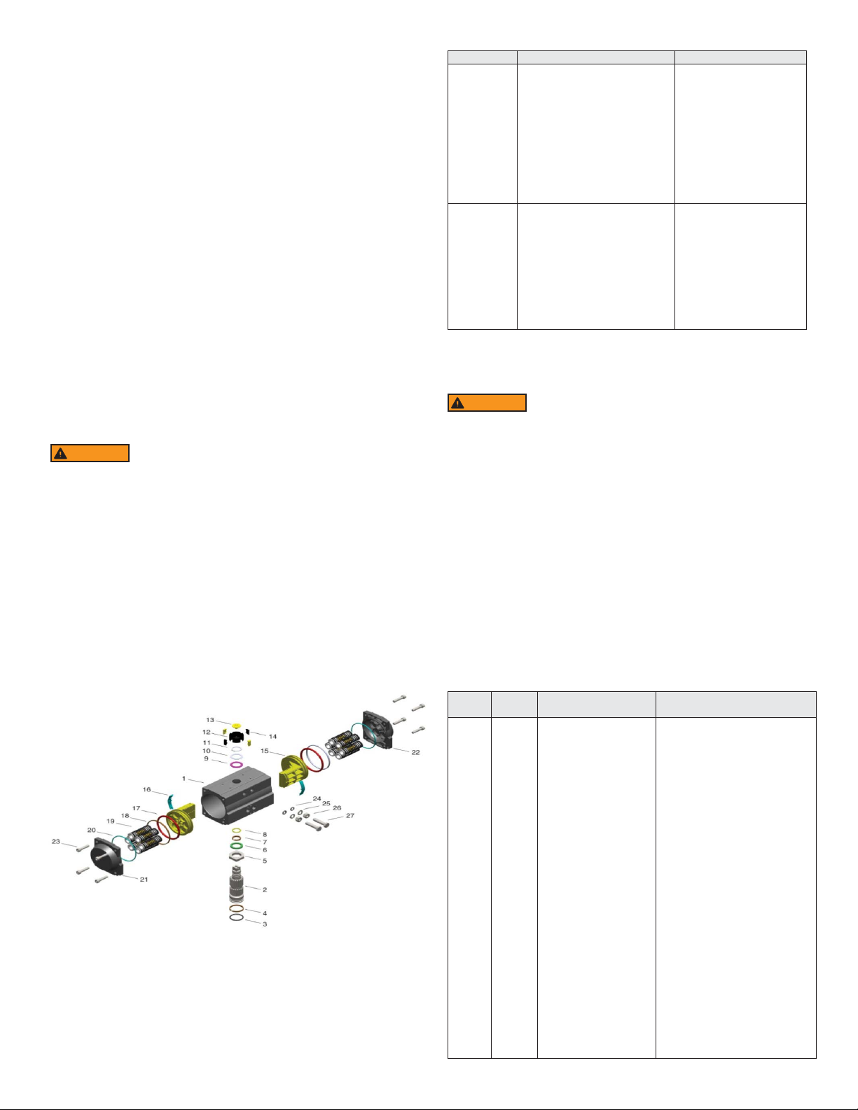
PNEUMATIC ACTUATOR
Note: For optimal operation, pneumatic actuators should be run with a supply of
clean, lubricated air.
Spring Return Actuator Operation
Air to PORT 2 (the left hand port) causes the actuator to turn counterclockwise
(CCW). Loss of air to PORT 2 causes air to exhaust and the actuator turns clockwise
(CW). This is the FAIL CLOSE operation.
Double Acting Actuators Operation
Air to PORT 2 (the left hand port) causes the actuator to turn counterclockwise
(CCW). Air to PORT 1 (the right hand port) causes the actuator to turn clockwise
(CW).
Pneumatic Actuator Maintenance
Routine maintenance of pneumatic actuator:
• Keep the air supply dry and clean
• Keep the actuator surface clean and free from dust
• Periodic checks should be done to make sure all ttings are tight
• Pneumatic actuators are supplied with lubrication to last the entire life span of the
actuator under normal operating conditions.
The outer surface of the pneumatic actuator should be clean to avoid friction
or corrosion. All ttings and connections should be tight to prevent leaks during
operation. Check the bolts mounting the valve to the actuator to make sure they
have not come loose during shipping or installation. Make sure the valve and
actuator are not rubbing or jamming against other components during operation.
The actuator should be inspected annually to make sure all ttings and bolts are
tight and nothing has come loose during operation.
Disassembling Pneumatic Actuators
WARNING
removed, and that the actuator has been disassembled from the valve.
1. Loosen the end cap fasteners (23) with a wrench (size varies depending on
actuator model). On the spring return actuator, alternate 3 to 5 turns on each
fastener until the springs are completely decompressed. Use caution when
removing the cap since the springs are under load until the fasteners are fully
extended.
2. Remove the pinion snap ring (13) with a lock ring tool. The indicator (12) may
now be removed.
3. Turn the pinion shaft (2) counter clockwise until the pistons are at the full end
of travel. Disengage the pistons (15) from the pinion. (Note: Low pressure air-
-3 to 5 psi MAXIMUM--might be required to force the pistons completely from the
body.) Note the position of the pistons before removing them from the actuator
body.
4. Remove the pinion through the bottom of the actuator. The actuator is now
completely disassembled.
Before beginning disassembly, ensure that the air supply to the
actuator has been disconnected, all accessories have been
Pneumatic Actuators Bill of Materials
Failures Inspection Items Corrective Action
Pneumatic
actuator
won’t operate
Pneumatic
actuator runs
slowly
Reassembling Pneumatic Actuators
WARNING
1. Apply a light lm of grease to all O-rings and the pinion before replacing.
2. Put the pinion (2) back through the actuator with the ats of the pinion shaft
running parallel with the body.
3. When reassembling the actuator, make sure that the piston racks are square
to the actuator body and returned to their original orientation.
(Note: The normal operation of all spring return pneumatic actuators is FAIL
CLOSED. To change the orientation to FAIL OPEN, rotate the racks 180º to
create a reverse operation.
4. When replacing springs in a spring return actuator, ensure that the springs are
replaced in their identical position in the end cap from which they were removed.
(Note: In some circumstances, you might want to change the standard 80 pound
spring set to t your application and available air pressure.)
5. Seal the end caps with a petroleum lubricant and bolt to actuator body.
6. Check the seal of the actuator by covering seal areas (pinion, end caps) with
soapy water and using low pressure air to the actuator to ensure that no bubbles
are produced.
Part
Number Quantity Part Name Material
1
2
3
4
5
6
7
8
9
10
11
12
13
14
15
16
17
18
19
20
21
22
23
24
25
26
27
4
1. Check the solenoid valve. Is the
coil burnt out or is the solenoid
spool?
2. The actuator will not move
because of debris in the gears.
3. The pneumatic line to the
actuator is distorted or smashed.
4. The pneumatic line is frozen
because of low temperatures and
moisture.
1. The air supply pressure is
insufcient.
2. Are other pneumatic devices
consuming the air required for the
actuator to operate?
3. The pneumatic actuator is
undersized for the application.
Be sure the actuator surfaces are free of debris and scratches
before reassembling.
1
1
1
1
1
1
1
1
1
1
1
1
1
4
2
2
2
2
5 to 12
2
1
1
8
2
2
2
2
Cylinder
Output shaft
O-ring
Bearing
Adjusting cam
Thrust bearing
Bearing
O-ring
Bearing
Gasket
Damping ring
Position indicator
Screw
Position indicating Inserts
Piston
Guide ring
O-ring
Guide ring
Spring assembly
O-ring
Left end cap
Right end cap
End cap bolt
O-ring
Gasket
Nut
Adjusting bolt
1. Replace the solenoid
valve coil or remove debris.
2. Disassemble the actuator,
clean the debris and
reassemble the actuator.
3. Replace pneumatic line to
the actuator.
4. Warm the pneumatic lines
and remove moisture from
supply lines.
1. Increase the air supply
pressure and look for leaks
in the supply pressure
pipeline.
2. Increase the air supply
or reduce the number of
devices operating at the
same time.
3. Replace the actuator with
a larger actuator.
Extruded aluminum alloy
Stainless steel
Fluorine silicon rubber
Nylon46
Stainless steel
Nylon46
Nylon46
Fluorine silicon rubber
Nylon46
Stainless steel
Stainless steel
PPPP+30%GF
PPPP+30%GF
PPPP+30%GF
Casting aluminum alloy
Nylon46
Fluorine silicon rubber
Fluorine-carbon composite material
Alloy spring steel
Fluorine silicon rubber
Casting aluminum alloy
Casting aluminum alloy
Stainless steel
Fluorine silicon rubber
Stainless steel
Stainless steel
Stainless steel
Page 5
MODEL CHART
Model
ACT-DA01
ACT-DA02
ACT-DA03
ACT-DA04
ACT-DA05
ACT-DA06
ACT-DA07
ACT-DA08
ACT-DA09
DA Double-Action Output Torque (lb-in)
Air Pressure
40 psi 50 psi 60 psi 70 psi 80 psi 90 psi 100 psi 110 psi 115 psi
49
104
182
302
396
567
845
1497
2253
61
130
228
377
495
709
1056
1871
2816
74
155
274
453
594
851
1267
2245
3379
86
181
319
528
693
993
1478
2619
3942
98
207
365
603
792
1135
1690
2993
4506
110
233
411
679
891
1277
1901
3367
5069
123
259
456
754
990
1419
2112
3742
5632
135
285
502
830
1089
1561
2323
4116
6195
142
300
529
875
1148
1649
2450
4340
6533
MODEL CHART
Model
ACT-SR02
ACT-SR03
ACT-SR04
ACT-SR05
ACT-SR06
ACT-SR07
ACT-SR08
ACT-SR09
ACT-SR10
ELECTRIC ACTUATORS
Electric Installation
1. Operate valve manually and place in the open position.
2. Remove any mechanical stops the valve might have. (DO NOT REMOVE ANY
PARTS NECESSARY FOR THE PROPER OPERATION OF THE VALVE,
SUCH AS THE PACKING GLAND, PACKING NUT, ETC.)
3. Ensure that the actuator output shaft and valve stem are aligned properly. If
they are not, operate the valve manually until they are correct.
4. Remove actuator cover.
5. Bring power to the actuator. CAUTION: Make sure power is OFF at the main
box.
6. Wire the actuator per the diagram attached to the inside of the cover. Special
actuators (those with positioner boards, etc.) will have diagrams enclosed
inside the cover.
7. Securely tighten bolts used to mount the actuator to a mounting bracket or
directly to the valve mounting pad if it is ISO5211 compliant.
8. Cycle the unit several times and check the open and closed positions of the
valve. Cams are pre-adjusted at the factory; due to the variety of valve designs
and types however, slight adjustments might be required.
9. Replace cover and tighten screws.
Spring
Quantity
10
10
10
10
10
10
10
10
10
SR Single Acting Pneumatic Actuator (lb-in)
Air Pressure
70 psi 80 psi 90 psi 100 psi 110 psi 115 psi Spring Torque
0°
90°
0°
90°
0°
90°
0°
90°
Start
111
199
348
430
608
783
1682
2303
3479
End
86
143
254
312
458
663
1208
1483
2274
Start
137
245
424
529
750
994
2056
2866
4337
End
112
189
330
411
599
874
1583
2046
3133
Start
163
291
499
628
891
1206
2430
3429
5195
End
138
235
405
510
741
1085
1957
2609
3991
Start
189
336
575
727
1033
1417
2804
3992
6053
End
164
280
481
609
883
1297
2331
3173
4849
0°
Start
215
382
650
826
1175
1628
3178
4556
6911
90°
0°
90°
End
Start
189
231
326
409
556
695
708
885
1025
1260
1508
1755
2705
3403
3736
4894
5707
7426
To Set The Closed Position
1. Apply power to terminals to move the valve toward the closed position. The
bottom cam and switch control the closed position. In the closed position, the set
screw in the bottom cam will be accessible.
2. If the valve is not closed completely:
a. Slightly loosen the set screw on the bottom cam.
b. Rotate the cam counterclockwise (CCW) by hand until the switch makes
contact. Contact is made when a slight click can be heard. By making
incremental CCW movements of the bottom cam, the valve can be positioned
precisely in the desired position.
c. When the top cam is set, tighten the set screw securely.
3. If the valve closes too far:
a. Apply power to terminals. This will begin to rotate valve CCW. When valve is
fully closed and in the exact position desired, remove power from actuator.
b. Loosen the set screw in the top cam.
c. Rotate the top cam clockwise (CW) until the switch arm drops off the round
portion of the cam onto the at section. A slight click can be heard as the
switch is no longer making contact with the round part of the cam.
d. Continue applying power to terminals until valve is in the desired position.
End
205
353
601
767
1110
1635
2930
4074
6222
90°
Start0°End
96
70
176
120
274
180
381
263
536
386
817
696
1416
938
2363
1575
3549
2407
To Set The Open Position
1. Cycle the valve to the open position by applying power to terminals. The top cam
and switch control this position. In the open position, the set screw in the top cam
will be accessible.
2. If the valve is not open completely:
a. Slightly loosen the set screw on the top cam.
b. Rotate the cam clockwise (CW) by hand until the switch makes contact.
Contact is made when a slight click can be heard. By making incremental
CW movements of the top cam, the valve can be positioned precisely in the
desired position.
c. When the top cam is set, tighten the set screw securely.
3. If the valve opens too far:
a. Apply power to terminals. This will begin to rotate valve CW. When valve is
fully open and in the exact position desired, remove power from actuator.
b. Loosen the set screw in the top cam.
c. Rotate the top cam counterclockwise (CCW) until the switch arm drops off
the round portion of the cam onto the at section. A slight click can be heard
as the switch changes state.
d. Continue applying power to terminals until valve is in the desired position.
5
Page 6
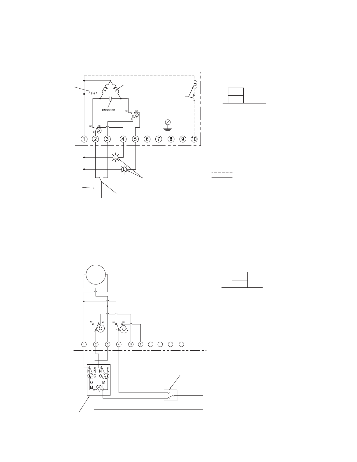
Electric Actuators Wiring Diagram: ACT-TI & ACT-MI
OPTIONAL
BRAKE
A.C.
SUPPLY
POWER
TI01-A to TI06-A1: 110 VAC, TI01-B to TI06-B: 220 VAC, TI01-C to TI06-C: 24 VAC
PSC MOTOR
OPTIONAL HEATER
& THERMOSTAT
SW. #1
SW.
#2
DPDT CONTROL SWITCH
N
HOT
SHOWN FOR ILLUSTRATION
ONLY
Wiring Diagrams for
GROUND
SCREW
FIELD WIRING
LIGHTS FOR REMOTE
POSITION INDICATION
SW. #2 OPEN LIMIT
SW. #1 CLOSE LIMIT
SWITCH LAYOUT
NOTES:
POWER TO TERMINALS ONE & TWO OPENS THE VALVE
(CCW ROTATION)
POWER TO TERMINALS ONE & THREE CLOSES THE VALVE
(CW ROTATION)
TERMINALS 4 & 5 ARE FOR LIGHT INDICATION
WIRING DIAGRAM ILLUSTRATES THE ACTUATOR IN THE
OPEN POSITION
OPTIONAL EQUIPMENT
FIELD WIRING
DC
-
+
MOTOR
SW.
#1
CA
M
REVERSING RELAY SUPPLIED BY CUSTOMER
ACTUATOR SHOWN IN OPEN
POSITION
SW.
#2
CA
M
FIELD WIRING
Wiring Diagrams for
TI01-D to TI06-D: 24 VDC
SPDT SWITCH SHOWN FOR
ILLUSTRATION ONLY
DC VOLTAGE
SW.#1
SW.#2
SWITCH #1 OPEN SWITCH
SWITCH #2 CLOSE SWITCH
OPERATION:
POWER TO 1 & 2 FOR CCW ROTATION
POWER TO 3 & 4 FOR CW ROTATION
TERMINALS 5 & 6 FOR FIELD LIGHT
INDICATION CONNECTION
-
+
6
Page 7
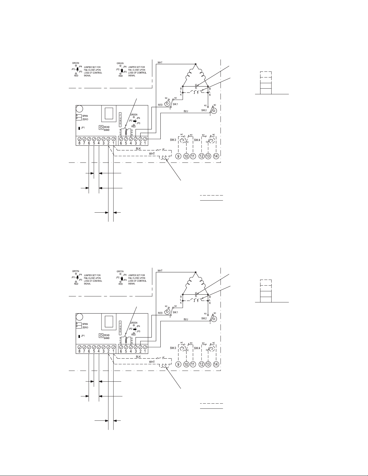
MI01-A to MI06-A1: 110 VAC, MI01-B to MI06-B: 220 VAC, MI01-C to MI06-C: 24 VAC
Wiring Diagrams for
JUMPER AS SHOWN BELOW IS FAIL IN
LAST POSITION UPON LOSS OF SIGNAL
1K OHM FEEDBACK
POTENTIOMETER
4-20mA POSITIONER
J2
4-20mA CONTROL
+
+
1PH-60HZ
POWER SUPPLY
-
HOT
SIGNAL
0-10VDC or 0-5VDC
CONTROL SIGNAL
REMOVE JP2, JP3 & JP4
N
FIELD
WIRING
J1
PSC MOTOR
AUXILIARY SWITCHES
OPTIONAL
HEATER &
THERMOSTAT
OPTIONAL
CAPACITOR
BRAKE
OPTIONAL
NOTE:
ACTUATOR SHIPPED IN OPEN
POSITION, 20mA REPRESENTS OPEN
POSITION. DO NOT ADJUST FEEDBACK
POTENTIOMETER OR LIMIT SWITCHES
THEY ARE FACTORY SET AND DO NOT
REQUIRE CALIBRATION. TO
CALIBRATE THE OPEN AND CLOSE
POSITION, USE THE ZERO (4mA) AND
SPAN (20mA) TRIM POTENTIOMETERS.
TO CALIBRATE, OPERAT E ACTUATOR
TO CLOSE POSITION AND ADJUST WITH
ZERO TRIM POT THEN OPERATE TO
OPEN POSITION AND SET USING SPAN
TRIM POT. NO FURTHER CALIBRATION IS
NECESSARY.
OPTIONAL EQUIPMENT
FIELD WIRING
WIRING DIAGRAM FOR 1Ph/60Hz ELECTRIC
ACTUATOR WITH 4-20mA, 0-5Vdc OR 0-10Vdc CONTROL.
SW. 4, OPEN
SW. 3, CLOSE
SW. 2, OPEN
SW. 1, CLOSE
JUMPER AS SHOWN BELOW IS FAIL IN
LAST POSITION UPON LOSS OF SIGNAL
1K OHM FEEDBACK
POTENTIOMETER
4-20mA POSITIONER
J2
4-20mA CONTROL
+
+
1PH-60HZ
POWER SUPPLY
-
HOT
SIGNAL
0-10VDC or 0-5VDC
CONTROL SIGNAL
REMOVE JP2, JP3 & JP4
N
FIELD
WIRING
Wiring Diagrams for
MI01-D to MI06-D: 24 VDC
PSC MOTOR
AUXILIARY SWITCHES
OPTIONAL
J1
HEATER &
THERMOSTAT
OPTIONAL
WIRING DIAGRAM FOR 1Ph/60Hz ELECTRIC
ACTUATOR WITH 4-20mA, 0-5Vdc OR 0-10Vdc CONTROL.
CAPACITOR
BRAKE
OPTIONAL
NOTE:
ACTUATOR SHIPPED IN OPEN
POSITION, 20mA REPRESENTS OPEN
POSITION. DO NOT ADJUST FEEDBACK
POTENTIOMETER OR LIMIT SWITCHES
THEY ARE FACTORY SET AND DO NOT
REQUIRE CALIBRATION. TO
CALIBRATE THE OPEN AND CLOSE
POSITION, USE THE ZERO (4mA) AND
SPAN (20mA) TRIM POTENTIOMETERS.
TO CALIBRATE, OPERAT E ACTUATOR
TO CLOSE POSITION AND ADJUST WITH
ZERO TRIM POT THEN OPERATE TO
OPEN POSITION AND SET USING SPAN
TRIM POT. NO FURTHER CALIBRATION IS
NECESSARY.
OPTIONAL EQUIPMENT
FIELD WIRING
SW. 4, OPEN
SW. 3, CLOSE
SW. 2, OPEN
SW. 1, CLOSE
7
Page 8
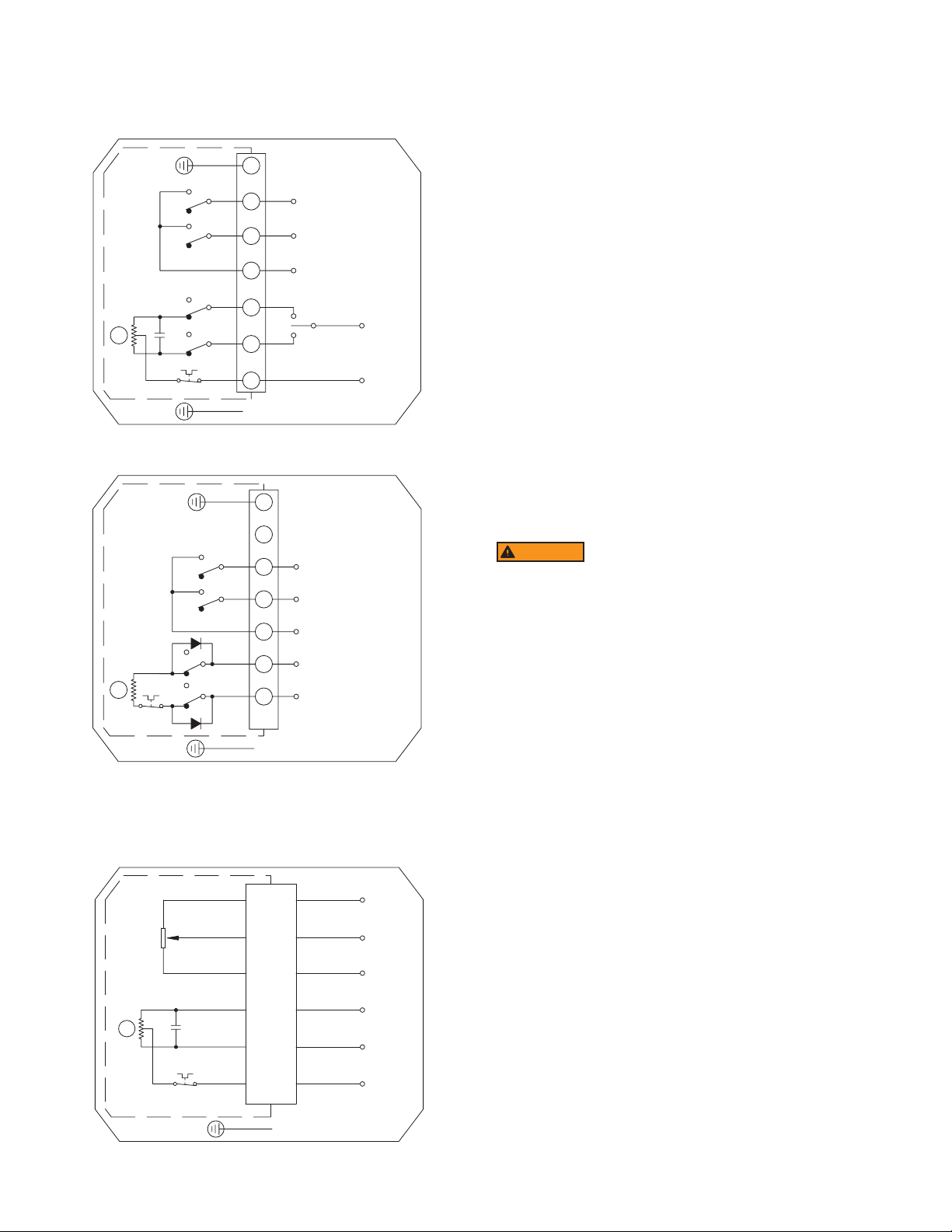
Electric Actuators Wiring Diagram: ACT-TD & ACT-MD
TD01-A to TD06-A: 110 VAC, TD01-B to TD06-B: 220 VAC,
C
M
M
Wiring Diagrams for
TD01-C to TD06-C: 24 VAC
PE
Y&G
7
GREY
BROWN
WHITE
BLACK
OLS
CLS
TD01-D to TD06-D: 24 VDC
PE
D1
OLS
CLS
D2
TD01-D to TD06-D: 24 VDC
6
5
4
3
RED
2
BLUE
1
PE
Wiring Diagrams for
Y&G
7
6
GREY
BROWN
WHITE
Wiring Diagrams for
BLACK
RED
5
4
3
2
1
PE
FULL-CLOSE SIGNAL
FULL-OPEN SIGNAL
COM
OPEN
K
CLOSE
FULL-CLOSE SIGNAL
FULL-OPEN SIGNAL
COM
-
+
CLOSE
L
N
+
-
OPEN
Note: To speed up installation of the control wires to the ACT-MDXX modulating
actuator, it is recommended to remove the control module from the actuator. The
control module can be removed by removing the two mounting screws on the left
and right of the control module. Install the control wires to the correct terminal points
and then reinstall the control module.
Electric Actuator Maintenance
Once the actuator has been properly installed, it requires no maintenance. The gear
train has been lubricated and in most cases will never be opened.
Duty Cycle Denition
“Duty Cycle” means the starting frequency.
Formula: Running Time
–
> Rest Time = Running Time x (1 - duty cycle) ÷ duty cycle
For example: The running time is 15 seconds
30% duty cycle 15 x [(1 - 30%) / 30%] = 35
75% duty cycle 15 x [(1 - 75%) / 75%] = 5
If the duty cycle is higher, the rest time will be shortened, which means the starting
frequency will be higher.
Thermal Overload
All actuators are equipped with thermal overload protection to guard the motor
against damage due to overheating.
Mechanical Overload
All actuators are designed to withstand stall conditions. It is not recommended to
subject the unit to repeated stall conditions.
Explosion-Proof Electric Actuators
WARNING
actuator while in a hazardous location. Removal of the
cover while in a hazardous location could cause ignition of
hazardous atmospheres.
2. DO NOT under any circumstances use an explosion-proof electric actuator in a
hazardous location that does not meet the specications for which the actuator
was designed.
3. Always verify that all electrical circuits are de-energized before opening the
actuator.
4. Always mount and cycle test the actuator on the valve in a non-hazardous
location.
5. When removing the cover, care must be taken not to scratch, scar of deform the
ame path of the cover and base of the actuator, since this will negate the NEMA
rating of the enclosure.
6. When replacing the cover, take care that the gasket is in place to assure proper
clearance after the cover is secured.
7. All electrical connections must be in accordance with the specications for which
the unit is being used.
8. Should the unit ever require maintenance, remove from the hazardous location
before attempting to work on the unit.
If the actuator is in a critical application, it is advisable to have a standby unit in
stock.
÷ (Running Time + Rest Time) x 100% = duty cycle
–
> The rest time will be 35 seconds
–
> The rest time will be 5 seconds
1. DO NOT under any circumstances remove the cover of the
PINK
RP
K
I
M
PURPLE
ORANGE
BLACK
C
RED
BLUE
OUTPUT SIGNAL
INPUT SIGNAL
SERVO CONTROLLER
POWER
PE
+
-
+
-
L
N
8
Page 9
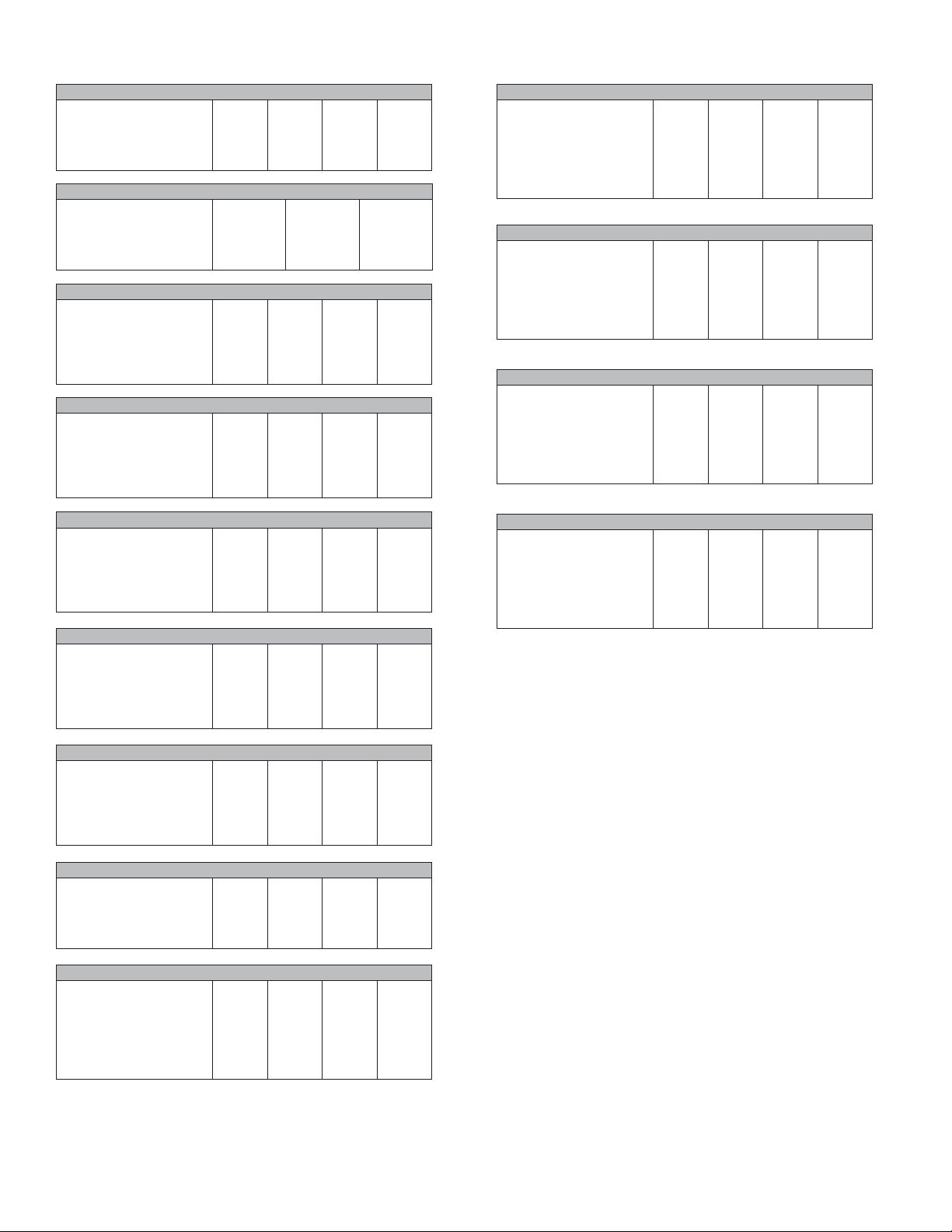
Electric Actuators Performance Rating
TD01
Voltage
Cycle Time
Duty Cycle (Two-Position)
AMP Draw
Torque (in-lb)
MD01
Voltage
Cycle Time
Duty Cycle (Modulating)
AMP Draw
Torque (in-lb)
TD02 and MD02 (MD Not Available in 24 VDC)
Voltage
Cycle Time
Duty Cycle (Two-Position)
Duty Cycle (Modulating)
AMP Draw
Torque (in-lb)
TD03 and MD03 (MD Not Available in 24 VDC)
Voltage
Cycle Time
Duty Cycle (Two-Position)
Duty Cycle (Modulating)
AMP Draw
Torque (in-lb)
TD04 and MD04 (MD Not Available in 24 VDC)
Voltage
Cycle Time
Duty Cycle (Two-Position)
Duty Cycle (Modulating)
AMP Draw
Torque (in-lb)
TD05 and MD05 (MD Not Available in 24 VDC)
Voltage
Cycle Time
Duty Cycle (Two-Position)
Duty Cycle (Modulating)
AMP Draw
Torque (in-lb)
TD06 and MD06 (MD Not Available in 24 VDC)
Voltage
Cycle Time
Duty Cycle (Two-Position)
Duty Cycle (Modulating)
AMP Draw
Torque (in-lb)
110 VAC
4 s
85%
0.24 A
177
110 VAC
10 s
85%
0.24 A
265
110 VAC
20 s
85%
85%
0.24 A
442
110 VAC
30 s
85%
85%
0.57 A
885
110 VAC
30 s
85%
85%
0.65 A
1770
110 VAC
30 s
85%
85%
1.12 A
3540
110 VAC
45 s
85%
85%
1.18 A
5210
220 VAC
4 s
85%
0.16 A
177
220 VAC
20 s
85%
85%
0.16 A
442
220 VAC
30 s
85%
85%
0.35 A
885
220 VAC
30 s
85%
85%
0.37 A
1770
220 VAC
30 s
85%
85%
0.57 A
3540
220 VAC
45 s
85%
85%
0.60 A
5210
220 VAC
10 s
85%
0.16 A
265
24 VAC
4 s
85%
0.28 A
177
24 VAC
20 s
85%
85%
1.28 A
442
24 VAC
30 s
85%
85%
2.03 A
885
24 VAC
30 s
85%
85%
3.57 A
1770
24 VAC
30 s
85%
85%
5.13 A
3540
24 VAC
45 s
85%
85%
6.04 A
5210
24 VDC
4 s
85%
1.28 A
177
24 VAC
10 s
85%
1.28 A
265
24 VDC
20 s
85%
-
1.28 A
442
24 VDC
30 s
85%
-
2.03 A
885
24 VDC
30 s
85%
-
3.57 A
1770
24 VDC
30 s
85%
-
5.13 A
3540
24 VDC
45 s
85%
-
6.04 A
5210
TI03 and MI03
Voltage
Cycle Time (Two-Position)
Cycle Time (Modulating)
Duty Cycle (Two-Position)
Duty Cycle (Modulating)
Full Load AMP Draw
Torque (in-lb)
TI04 and MI04
Voltage
Cycle Time (Two-Position)
Cycle Time (Modulating)
Duty Cycle (Two-Position)
Duty Cycle (Modulating)
Full Load AMP Draw
Torque (in-lb)
TI05 and MI05
Voltage
Cycle Time (Two-Position)
Cycle Time (Modulating)
Duty Cycle (Two-Position)
Duty Cycle (Modulating)
Full Load AMP Draw
Torque (in-lb)
TI06 and MI06
Voltage
Cycle Time (Two-Position)
Cycle Time (Modulating)
Duty Cycle (Two-Position)
Duty Cycle (Modulating)
Full Load AMP Draw
Torque (in-lb)
MAINTENANCE/REPAIR
Upon nal installation of the Series WE, only routine maintenance is required. The
Series WE is not eld serviceable and should be returned if repair is needed. Field
repair should not be attempted and may void warranty.
WARRANTY/RETURN
Refer to “Terms and Conditions of Sale” in our catalog and on our website. Contact
customer service to receive a Return Goods Authorization number before shipping
the product back for repair. Be sure to include a brief description of the problem plus
any additional application notes.
110 VAC
5 s
10 s
25%
75%
0.38
300
110 VAC
10 s
20 s
25%
75%
0.38
400
110 VAC
15 s
30 s
25%
75%
0.38
675
110 VAC
15 s
30 s
25%
75%
0.38
1000
220 VAC
5 s
10 s
25%
75%
0.18
300
220 VAC
10 s
20 s
25%
75%
0.18
400
220 VAC
15 s
30 s
25%
75%
0.18
675
220 VAC
15 s
30 s
25%
75%
0.18
1000
24 VAC
5 s
5 s
25%
75%
0.7
300
24 VAC
10 s
10 s
25%
75%
0.9
400
24 VAC
15 s
15 s
25%
75%
0.7
675
24 VAC
15 s
15 s
25%
75%
1.1
1000
24 VDC
5 s
5 s
25%
75%
0.7
300
24 VDC
10 s
10 s
25%
75%
0.9
400
24 VDC
15 s
15 s
25%
75%
0.7
675
24 VDC
15 s
15 s
25%
75%
1.1
1000
TI01
Voltage
Cycle Time
Duty Cycle (Two-Position)
Full Load AMP Draw
Torque (in-lb)
TI02 and MI01, MI02
Voltage
Cycle Time (Two Position)
Cycle Time (Modulating)
Duty Cycle (Two-Position)
Duty Cycle (Modulating)
Full Load AMP Draw
Torque (in-lb)
110 VAC
2.5 s
25%
0.64
100
110 VAC
5 s
10 s
25%
75%
0.38
200
220 VAC
2.5 s
25%
0.32
100
220 VAC
5 s
10 s
25%
75%
0.18
200
24 VAC
2.5 s
25%
0.4
100
24 VAC
5 s
5 s
25%
75%
0.7
200
24 VDC
2.5 s
25%
0.4
100
24 VDC
5 s
5 s
25%
75%
0.7
200
9
Page 10

NOTES
__________________________________________________________________________________________________________________________________________
__________________________________________________________________________________________________________________________________________
__________________________________________________________________________________________________________________________________________
__________________________________________________________________________________________________________________________________________
__________________________________________________________________________________________________________________________________________
__________________________________________________________________________________________________________________________________________
__________________________________________________________________________________________________________________________________________
__________________________________________________________________________________________________________________________________________
__________________________________________________________________________________________________________________________________________
__________________________________________________________________________________________________________________________________________
__________________________________________________________________________________________________________________________________________
__________________________________________________________________________________________________________________________________________
__________________________________________________________________________________________________________________________________________
__________________________________________________________________________________________________________________________________________
__________________________________________________________________________________________________________________________________________
__________________________________________________________________________________________________________________________________________
__________________________________________________________________________________________________________________________________________
__________________________________________________________________________________________________________________________________________
__________________________________________________________________________________________________________________________________________
__________________________________________________________________________________________________________________________________________
__________________________________________________________________________________________________________________________________________
__________________________________________________________________________________________________________________________________________
__________________________________________________________________________________________________________________________________________
__________________________________________________________________________________________________________________________________________
__________________________________________________________________________________________________________________________________________
__________________________________________________________________________________________________________________________________________
10
Page 11

NOTES
__________________________________________________________________________________________________________________________________________
__________________________________________________________________________________________________________________________________________
__________________________________________________________________________________________________________________________________________
__________________________________________________________________________________________________________________________________________
__________________________________________________________________________________________________________________________________________
__________________________________________________________________________________________________________________________________________
__________________________________________________________________________________________________________________________________________
__________________________________________________________________________________________________________________________________________
__________________________________________________________________________________________________________________________________________
__________________________________________________________________________________________________________________________________________
__________________________________________________________________________________________________________________________________________
__________________________________________________________________________________________________________________________________________
__________________________________________________________________________________________________________________________________________
__________________________________________________________________________________________________________________________________________
__________________________________________________________________________________________________________________________________________
__________________________________________________________________________________________________________________________________________
__________________________________________________________________________________________________________________________________________
__________________________________________________________________________________________________________________________________________
__________________________________________________________________________________________________________________________________________
__________________________________________________________________________________________________________________________________________
__________________________________________________________________________________________________________________________________________
__________________________________________________________________________________________________________________________________________
__________________________________________________________________________________________________________________________________________
__________________________________________________________________________________________________________________________________________
__________________________________________________________________________________________________________________________________________
__________________________________________________________________________________________________________________________________________
11
Page 12

NOTES
__________________________________________________________________________________________________________________________________________
__________________________________________________________________________________________________________________________________________
__________________________________________________________________________________________________________________________________________
__________________________________________________________________________________________________________________________________________
__________________________________________________________________________________________________________________________________________
__________________________________________________________________________________________________________________________________________
__________________________________________________________________________________________________________________________________________
__________________________________________________________________________________________________________________________________________
__________________________________________________________________________________________________________________________________________
__________________________________________________________________________________________________________________________________________
__________________________________________________________________________________________________________________________________________
__________________________________________________________________________________________________________________________________________
__________________________________________________________________________________________________________________________________________
__________________________________________________________________________________________________________________________________________
__________________________________________________________________________________________________________________________________________
__________________________________________________________________________________________________________________________________________
__________________________________________________________________________________________________________________________________________
__________________________________________________________________________________________________________________________________________
__________________________________________________________________________________________________________________________________________
__________________________________________________________________________________________________________________________________________
__________________________________________________________________________________________________________________________________________
__________________________________________________________________________________________________________________________________________
__________________________________________________________________________________________________________________________________________
__________________________________________________________________________________________________________________________________________
__________________________________________________________________________________________________________________________________________
__________________________________________________________________________________________________________________________________________
©Copyright 2017 Dwyer Instruments, Inc. Printed in U.S.A. 11/17 FR# 444339-00 Rev. 1
W.E. ANDERSON
A DIVISION OF
DWYER INSTRUMENTS, INC.
P.O. BOX 373 • MICHIGAN CITY, INDIANA 46360, U.S.A.
12
Phone: 219/879-8000
Fax: 219/872-9057
www.dwyer-inst.com
e-mail: [email protected]
 Loading...