

Page 1
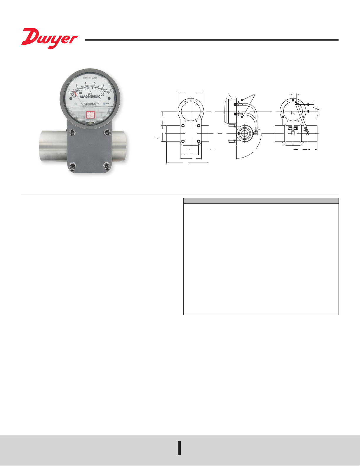
Series VFLO Venturi Flow Meter with Magnehelic® Gage
®
Specications - Installation and Operating Instructions
GAGE ASSEMBLY IS SHOWN
FLOW
[B]
[øC]
[ø4.750]
[E]
[A]
TO ILLUSTRATE MOUNTING
ORIENTATION
[D]
[F]
(1) MOUNTING
SCREWS
90° APPROX.
Bulletin F-VFLO
SIDE PORTS
[.687]
PLUGGED
[.500]
[1.250]
[G]
[H]
The Venturi Flow Meter with Magnehelic® Gage is fabricated from aluminum and
has a gradual Venturi prole to reduce pressure losses through the meter. Flexible
connections enable the meter to be used in vertical or horizontal applications. The
Magnehelic
pressure reading. Each meter is calibrated at standard atmospheric conditions. The
dual scale reads in SCFM and in w.c. The meter is supplied with ow correction
calculation sheet for various ow conditions. It is available in line sizes from 1˝ to 4˝
and can handle vacuum and pressure applications.
MOUNTING
Location:
The ow tube should be installed with minimum 8 diameters of pipe run ahead and 5
diameters of pipe run after. This will ensure steady ow and accurate readings.
Installation:
1. The meter can be installed in a vertical or horizontal position. The Magnehelic
gage must be positioned such that it is read in a horizontal orientation. The meter
comes in a horizontal left to right conguration. If a vertical orientation is required
remove the three mounting screws (1) from the back of the Magnehelic
reposition the gage within the bracket and re-tighten the screws.
2. The Magnehelic
make sure to keep the Magnehelic
Condensation may collect in the tube if it is below the gage and cause false
readings.
3. The Venturi Flow Tube must be connected in the correct orientation. For example,
in a left to right ow, the high pressure side which is on the left connects to the
high pressure port on the Magnehelic
and connects to the low pressure port of the Magnehelic
®
gage provides a large, clear and accurate display of your differential
®
gage,
®
gage can be mounted remotely from the meter. If this is done
®
gage above the Venturi Flow Tube assembly.
®
gage. The low pressure side is on the right
®
gage.
®
SPECIFICATIONS
Service: Air and non-combustible, compatible gases.
Wetted Materials: Aluminum, silicone, acrylic, polycarbonate, high carbon steel,
low carbon steel, brass, paper, acrylic paint, enamel paint, alkyd coating, nickel
plate, zinc plate, helsel FC, 300 series stainless steel, PTFE, Loctite
commercial black rubber, neoprene, samarium cobalt, nickel alloy steel cover,
beryllium copper.
Housing: Die cast aluminum case and bezel, with acrylic cover. Exterior nish is
coated gray to withstand 168 hour salt spray corrosion test.
Accuracy: ± 2.5% FS.
Pressure Limits: -20˝ Hg to 15 psig (-0.677 bar to 1.034 bar); MP option: 35 psig
(2.41 bar). For applications with high cycle rate within gage total pressure rating,
next higher rating is recommended.
Overpressure: Relief plug opens at approximately 25 psig (1.72 kPa).
Temperature Limits: 20 to 140°F (-6.67 to 60°C).
Size: 4˝ (101.6 mm) diameter dial face.
Mounting Orientation: Diaphragm in vertical position. Consult factory for other
position orientations.
Process Connection: Female NPT of nominal line size (from 1˝ to 4˝).
Weight: Gage only: 1 lb 2 oz (510 g), MP & HP 2 lb 2 oz (963 g). Venturi: 1˝: 3 lbs
(1.36 kg); 1-1/2˝: 4.5 lbs (2.04 kg); 2˝: 6 lbs (2.72 kg); 3˝: 11 lbs (4.99 kg); 4˝: 18 lbs
(8.16 kg).
®
AV sealant,
DWYER INSTRUMENTS, INC.
P.O. BOX 373 • MICHIGAN CITY, INDIANA 46360, U.S.A.
Phone: 219/879-8000
Fax: 219/872-9057
Loctite® is a registered trademark of Henkel Corporation
www.dwyer-inst.com
e-mail: [email protected]
Page 2

Venturi Flow Meter with Magnehelic® Gage - Flow Correction Equations
The stocked venturi ow meter is built with a gauge calibrated to read the correct
SCFM ow rate when operating in a process at 68°F, 14.7 psia (standard temperature
and pressure). If the ow meter is operating in a process line with different operating
pressure and temperature then the operator will have to apply a correction factor to the
SCFM reading on the gauge to obtain the accurate SCFM measurement in the pipe.
Converting measured ow on a calibrated gauge to the actual ow:
actual = Fcalibrated
F
Pactual(Tcalibrated + 460)
calibrated(Tactual + 460)
P
Where:
actual: Actual SCFM ow rate in the pipe.
F
F
calibrated: The SCFM ow rate measured directly off the gauge when operating.
P
calibrated: 14.7psia – standard pressure for which the gauges are calibrated at.
T
calibrated: 68°F – standard temperature for which gauges are calibrated at.
P
actual: The actual operating pressure of the process in psia.
T
actual: The actual operating temperature of the process in °F.
For example:
The stocked owmeter was calibrated at 14.7 psia and 68°F. It is now being deployed
in a process operating under vacuum at 10˝ Hg and 100°F. The current reading on the
gauge is shown to be 100 SCFM. To determine the actual SCFM rate:
calibrated: 100 SCFM.
F
To convert the actual SCFM values calculated above to the actual ACFM values, the
following equation can be used:
acfm = Fscfm x (Pstandard x (460 + Tactual))/(Pactual x (460 + Tstandard)
F
F
acfm = 79.2 x (14.7 x (460 + 100))/(9.79 x (460 + 68))
F
acfm = 79.2 x 1.59
F
acfm = 126 ACFM
MAINTENANCE
After nal installation of the Venturi Flow Meter with Magnehelic
®
Gage, no routine
maintenance is required. A periodic check of system calibration is suggested. These
devices are not eld repairable and should be returned if repair is needed. Be sure to
include a brief description of the problem plus any relevant application notes. Contact
customer service to receive a return goods authorization number before shipping.
P
calibrated: 14.7psia
T
calibrated: 68°F
P
actual: 10˝ Hg(g) = 14.7psia - (10˝Hg x 0.491 )
=9.79 psia.
P
actual: 100°F
Factual = Fcalibrated
Factual = 100
F
actual = 79.2 SCFM
Pactual(Tcalibrated + 460)
calibrated(Tactual + 460)
P
9.79(68 + 460)
14.7(100 + 460)
psi
˝Hg
DWYER INSTRUMENTS, INC.
P.O. BOX 373 • MICHIGAN CITY, INDIANA 46360, U.S.A.
Printed in U.S.A. 3/19 FR# 443654-00 Rev. 6©Copyright 2019 Dwyer Instruments, Inc.
Phone: 219/879-8000
Fax: 219/872-9057
www.dwyer-inst.com
e-mail: [email protected]
 Loading...