

Page 1
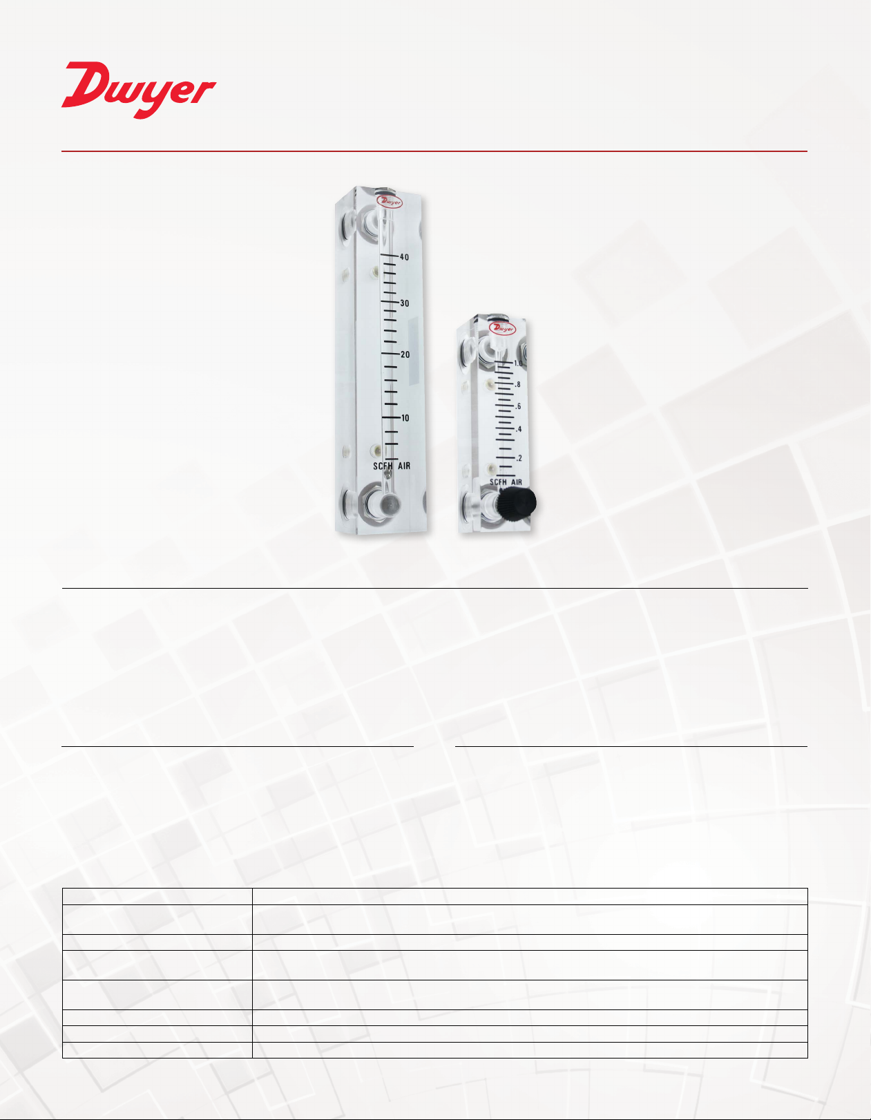
SERIES VF | VISI-FLOAT® ACRYLIC FLOWMETER
®
FEATURES/BENEFITS
• Bodies are cut and precision machined from solid, clear acrylic blocks allowing for complete visual inspection
•Whitebackgroundallowsforbettervisibilityoftheoatincreasingreadingaccuracy
• Direct reading scales are hot stamped into the plastic eliminating the need for troublesome conversions and increasing
product operating life
• Precision machined tapered bore enables high repeatability
• Low installation costs with back or end connection options with metal mounting inserts that can be supported directly by
system piping
DESCRIPTIONAPPLICATIONS
• Medical equipment
• Laboratory equipment
• Air samplers
• Gas analyzers
• Pollution monitors
• Chemical injectors
• Cabinet purging
The Series VF Visi-Float® Acrylic Flowmeter is a line of direct reading,
precision machined, clear acrylic body owmeters suitable for both gas
and liquid applications. The fabrication of the Visi-Float® owmeter is
backed by over 60 years of experience in acrylic instrument machining.
This series consists of 2˝ (51 mm) and 4˝ (102 mm) scales with optional
precision metering valves.
SPECIFICATIONS
Service Compatible gases and liquids.
Wetted Materials Body: Acrylic plastic; O-ring: Buna-N (uoroelastomer available); Metal parts: Brass standard, SS optional;
Float: SS, black glass, aluminum, K monel depending on range.
Accuracy VFA: 5% FS; VFB: 3% FS.
Temperature and Pressure Limits Without valve: 100 psig (6.9 bar) @ 150°F (65°C); 150 psig (10 bar) @ 100°F (38°C); With valve: 100 psig (6.9
bar) @ 120°F (48°C).
Process Connection 1/8˝ female NPT. VFB ranges 85 and 86 have 1/4˝ NPT back connections or 3/8˝ NPT end connections. These
ranges are not available with brass valves.
Scale Length VFA: 2˝ typical length; VFB: 4˝ typical length.
Mounting Connection Mount in vertical position.
Weight VFA: 4.0 to 4.8 oz (.11 to .14 kg); VFB: 7.2 to 8.8 oz (.20 to .25 kg).
Page 2
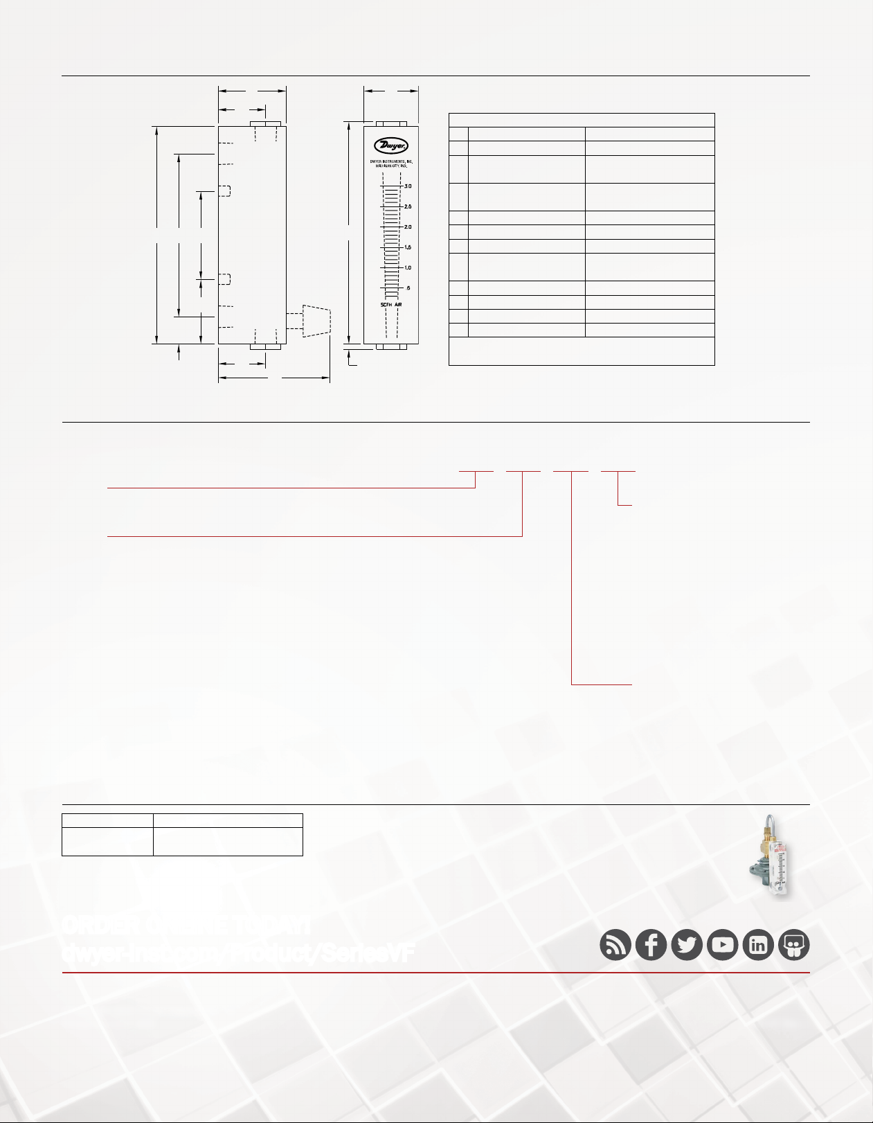
DIMENSIONS
F
L
FULL OPEN
M
A
C
B
E
D
M
I
K
N
HOW TO ORDER
Use the bold characters from the chart below to construct a product code.
SERIES
VFA: 2˝ (50.8 mm) scale
VFB: 4˝ (101.6 mm) scale
RANGE
VFA
-1: 0.1 to 1 SCFH air
-2: 0.2 to 2 SCFH air
-3: 0.6 to 5 SCFH air
-4: 1 to 10 SCFH air
-5: 2 to 20 SCFH air
-6: 4 to 30 SCFH air
-7: 5 to 50 SCFH air
-8: 10 to 100 SCFH air
-9: 20 to 200 SCFH air
-21: 0.06 to 0.5 LPM air
-22: 0.15 to 1 LPM air
-23: 0.6 to 5 LPM air
-24: 1 to 10 LPM air
-25: 3 to 25 LPM air
-26: 6 to 50 LPM air
-27: 10 to 100 LPM air
-32: 6 to 50 CC/min water
-33: 10 to 100 CC/min water
-34: 20 to 200 CC/min water
-41: 0.6 to 5 GPH water
-42: 2 to 10 GPH water
-43: 3 to 20 GPH water
-44: 8 to 40 GPH water
VFB
-50: 0.3 to 3 SCFH air
-91: 1 to 10 SCFH air
-51: 2 to 20 SCFH air
-52: 4 to 40 SCFH air
-53: 10 to 100 SCFH air
-54: 10 to 150 SCFH air
-55: 20 to 200 SCFH air
-90: 0.3 to 3 SCFM air
-60: 100 to 1000 CC/min air
-65: 0.2 to 4 LPM air
-66: 1 to 10 LPM air
-67: 1 to 20 LPM air
-68: 3 to 30 LPM air
-69: 4 to 40 LPM air
-82: 2 to 30 CC/min water
-80: 0.5 to 12 GPH water
-83: 1 to 20 GPH water
-84: 6 to 40 GPH water
-81: 6 to 60 GPH water
-85: 0.2 to 2 GPM water
-86: 0.6 to 5 GPM water
DIMENSIONS in [mm]
Model VFA Model VFB
A 4 [101.6] 6-1/2 [165.1]
B 3 [76.20]
1/8˝ female NPT
C 1-5/8 [41.28]
10-32 thread
D 1/2 [12.70] 1/2 [12.70]
E 1-3/16 [30.16] 1-1/2 [38.10]
F 1-1/4 [31.75] 1-1/4 [31.75]
I 2-1/16 [52.39]
(BV or SSV only)
K 4-3/32 [104.0] 6-19/32 [169.9]
L 1 [25.40] 1-3/8 [34.93]
M 7/8 [22.23] (EC only) 7/8 [22.23] (EC only)
N 3/32 [2.381] (EC only) 3/32 [2.381] (EC only)
*VFB ranges 85 and 86 have 1/4” NPT back
connections or 3/8” NPT end connections.
VFA -1 -SSV -NIST
5-1/2 [139.7]
1/8˝ female NPT*
3-1/2 [88.90]
10-32 thread
2-1/16 [52.39]
(BV or SSV only)
OPTIONS
-ARB: Arbitrary scale
-AT: Aluminum tag
-EC: End connections
-NIST: NIST traceable calibration
certicate
-PF: Adjustable pointer ag
-PTFE: PTFE valve seat
-SPCL: Special cleaning
-SS: Stainless steel wetted parts
-VIT : Fluoroelastomer O-rings
-WL: Without logo
VALV E
BLANK: Standard (no valve)
-BV: Brass valve
-SSV: Stainless steel valve
ACCESSORIES
Model Description
RKA
RK-RMB
Regulator kit for Series VFA
Regulator kit for Series VFB
Regulator Kits
Available as optional extras for the Visi-Float
for use where inlet air pressure uctuates widely and constant ow is required. The
regulator maintains a constant pressure differential of approximately 3 ±0.15 psig.
Supply pressure must be at least 3 psig above the owmeter discharge to operate.
The standard regulator may be used up to 200 scfh.
®
owmeter models. Recommended
ORDER ONLINE TODAY!
dwyer-inst.com/Product/SeriesVF
DWYER INSTRUMENTS, INC.
©Copyright 2020 Dwyer Instruments, Inc.
Printed in U.S.A. 8/20 DS-VF Rev. 1
Important Notice: Dwyer Instruments, Inc. reserves the right to make changes to or discontinue any product or service identied in this publication without notice. Dwyer advises its customers to obtain the
latest version of the relevant information to verify, before placing any orders, that the information being relied upon is current.
 Loading...