

Page 1
Product specifications and ordering information
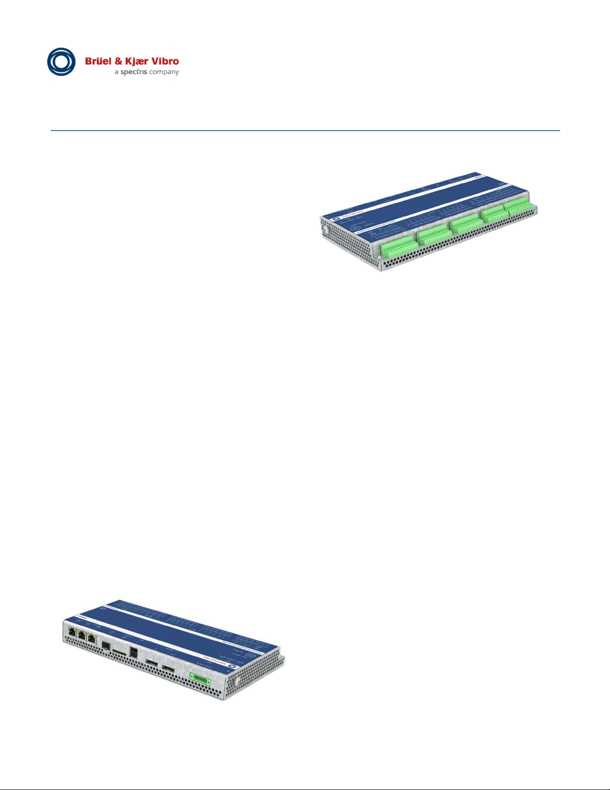
At a Glance Overview
The VCM-3 is the cost effective 12 channel data
acquisition hub targeted at monitoring of auxiliary
machines, balance-of-plant (BOP) machines and less
critical assets as part of enterprise Industry 4.0
digitization efforts. Multiple VCM-3 monitors can be
connected to your network with wired technology
providing the next generation of asset condition
monitoring without batteries or spotty occasional
monitoring provided by route based or multiplexed
systems.
The monitor devices are robust, simple to install, and
provide industry standard CCS (Constant Current
Supply) acceleration sensor inputs and power. Along
with advanced signal processing the VCM-3 provides
extensive alarm capability. For trouble shooting and
commissioning purposes for each channel and main
descriptor a spectra (FFT) type data plot can be
accessed via the built-in VCM-3 Homepage (Web
server).
The VCM-3 will end your frustration monitoring your
balance-of-plant (BOP) and smaller less critical
machines. These machines are often difficult to
identify and diagnose potential problems especially
with the periodic low bandwidth data provided by most
existing systems. These machines need high fidelity
continuous data streams for effective monitoring.
Whether your monitoring strategy uses alternative
on-premise or internal VCM-3 descriptor alarming
- for instance to comply to ISO 10816 respectively
20816 standard - be ready for a step change down in
in the cost of maintaining and understanding your less
critical machines.
VIBRO Condition Monitoring 3 (VCM-3)
Spanning the gap between periodic monitoring with
data collectors and wireless sensors and the need for
continuously connected assets managed 24/7 for
reliability and plant optimization. The VCM-3 provides
continuous monitoring of BOP and spared equipment
in a wide range of industries. Often these mechanical
assets are naturally located with multiple machines in
close proximity. The VCM-3 is ideal for continuously
monitoring up to four (or even six) machines -typically
being equipped with two bearings- utilizing the twelve
dynamic vibration signal inputs.
This data is concentrated into a single network stream
using Modbus TCP Server or OPC UA Server acting
as a functional edge device powering the enterprise
digital transformation.
NOTE, the VCM-3 has an integrated OPC UA Server
functionality in the hardware. All measurement, alarm
and status data can be transferred directly from the
VCM-3 hardware to an OPC UA Client application.
Thanks to the built-in network switch functionality, no
additional external Ethernet switch hardware is
required when integrating multiple VCM-3 devices.
The available optical SFP network connector supports
a stable long distance network connection.
The VCM-3 processes advanced descriptors which
are extracted key features from parallel AD
processing for direct monitoring of roller element
bearings (REB). Use of modern electronic design
elements allows the VCM-3 to provide continuous
monitoring of the 12 channels of sensor input at a very
competitive cost point that will help you accelerating
your enterprise’s digital transformation.
© Brüel & Kjaer Vibro ● C107757.002 / V02 Page 1 of 10
Technical alterations reserved!
CORPORATE DOCUMENT
Page 2

EN
Key Features and System Benefits
Fault detection – Descriptors for trending
VCM-3 is using descriptors for fault detection.
A descriptor is created by post processing the raw
vibration (sensor) signal into one or more scalar
values. A descriptor value is very well suited for
long term trending to indicate failure modes of
machines. VCM-3 measures a range of
descriptors such as real time standardized
bandpass filters for true energy measurements,
and envelope bandpass for bearing fault
detection.
High number of input channels/High value
Suitable for advanced condition monitoring of
several machines in one device.
All input channels are sampled simultaneously
(synchronous sampling).
12 Dynamic vibration input channels,
sampled at 204,8K samples per second via
24 Bit analog to digital converter (ADC)
Field mountable edge device
Environmentally robust -40 to +60 °C (-40F to
+140F) operation with built in protocols for
MODBUS TCP and OPC UA.
VCM-3 can be installed as field monitors mounted
at remote locations next to the machines* or in an
instrument cabinet.
*in a suitable field housing
Robust cybersecurity
The ports in our VCM-3 hardware have been
hardened with encryption and designed to push
data out to upper networks without exposing
critical infrastructure to external vulnerabilities.
It is specifically designed to work with firewalls,
data diodes, and multi-tiered networks to meet
industry’s most stringent data security
requirements
OPC UA Server embedded in the device
Remove the need for additional software and
PC/Server hardware infrastructure for the
OPC UA Server application as OPC UA is
embedded directly into the VCM-3 hardware
device.
VCM-3 Homepage (embedded Web server)
Acceleration/Velocity spectrum and Envelope
spectrum plot (all FFT, Hanning Window) can
be accessed for each of the 12 dynamic vibration
input channels via the built-in Homepage (Web
server).
This can perfectly be used for commissioning or
remote diagnostic access use cases.
Field proven
Based off the third generation of the world’s most
popular wind turbine monitoring system with over
tens of thousands installed units.
Rolling Element Bearing (REB) descriptors
Acceleration band pass with flexible filter
corners
(simultaneously measured detectors rms,
peak, crest factor)
Velocity (integrated from acceleration)
with flexible filter corners
(rms, ISO 10816 / ISO 20816 support)
Enveloped Bearing Condition ECU with
flexible filter corners
Designed for the future
(without change of VCM-3 device hardware)
The computational power, the existing sensor
input and analysis capabilities, and the flexibility in
the design make VCM-3 a technology leader for
many years to come. Supports any state-of-the-art
condition monitoring method and provides a
platform for customizations and development of
future new monitoring methods.
Page 2 of 10 © Brüel & Kjaer Vibro ● C107757.002 / V02
Technical alterations reserved!
Page 3

Product specifications and ordering information
units)
(Imperial units)
VIBRO Condition Monitoring 3 (VCM-3)
VCM-3 System Components
EN
A VCM-3 system consists of the following basic
components:
VCM-3 device hardware
VCM-3 Homepage
(built-in Web server)
VCM-3 Editor
(Software application to set up the
configurable parameters of a Standard
Monitoring Template and download to the
VCM-3 Web server)
NOTE!
To start up a VCM-3, a personal computer (PC) with
Microsoft Windows operating system is required.
For more information please consult the dedicated
section Ordering Information and VCM-3 Editor –
PC and Software Requirements at the end of this
document.
Fault detection, Trending and
Identification
The VCM-3 has been designed to continuously
acquire different characteristic values from the sensor
raw input signal of the connected sensor. Each of
these characteristic values are captured as a
“Descriptor”. In future version releases, descriptors
can be customized to accurately monitor for specific
component failure modes. An increase in the level of a
descriptor is a symptom of a developing fault on the
machine. A descriptor respectively series may be the
ECU value, which indicates a bearing fault.
A descriptor value may also be used to express the
severity of the vibration level of the component
compared to international standards such as ISO
10816. The powerful inbuilt signal processing
capabilities enables the VCM-3 to extract a number of
descriptors measured simultaneously on the
independent measurement channels.
Experience shows that long term trending on the each
of the descriptors derived from the input signal
provides a very sensitive measure of the operational
state of the machine and gives an early indication of a
progressing fault, thus maximizing lead time to plan a
service shutdown or to provide enough evidence to
postpone a repair to the next scheduled shutdown.
Monitoring Templates
The configuration of the VCM-3 hardware units is
organized in “Monitoring Templates”.
The VCM-3 can be loaded with different monitoring
templates implementing a specific monitoring strategy
adapted to the type of machine and monitoring
requirements without the need for changing the
hardware.
Standard Monitoring Template
To simplify the system set up work a set of two
Standard (Master) Monitoring Templates- is supplied
together with the VCM-3 System. Each of these
templates has been developed to cover applications
for the following types of machinery:
Standard Monitoring Templates*
No. Template
name
1.1 VCM-3-TPL-
AUX-SI
1.2 VCM-3-TPL-
AUX-IMP
*Further Standard Monitoring Templates supporting other
machine/asset applications to come in future. Please contact
your local Sales representative.
Machine/Asset
Application
Auxiliary
Machinery, REB,
Constant Speed
(SI = Metric
Auxiliary
Machinery, REB,
Constant Speed
Input
channels
12 accel.
12 accel.
© Brüel & Kjaer Vibro ● C107757.002 / V02 Page 3 of 10
Technical alterations reserved!
Page 4
EN
Technical Specification – Standard Monitoring Template
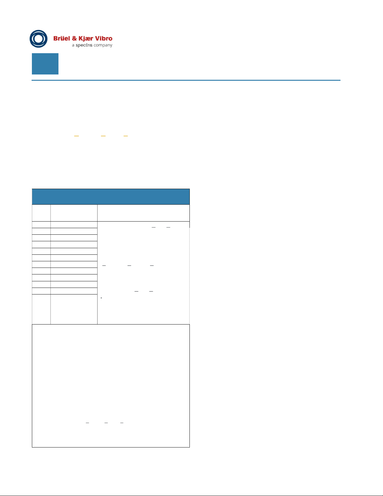
The VCM-3 input channels enable acceleration
sensors (CCS, Constant Current Supply) to be used
as signal inputs. The table below shows how each
channel of the VCM-3 is configured for each of the
available Standard Monitoring Templates.
All descriptors on all measurement channels are
measured in parallel (simultaneously) and are
continuously updated.
Sensor and Descriptor configuration on input channels
(Chl.)
Chl. Sensor Input Descriptors
(each measurement once/Chl.)
1 Accel. (CCS) Acceleration “BP” (Band Pass):
2 Accel. (CCS)
3 Accel. (CCS)
4 Accel. (CCS)
5 Accel. (CCS)
6 Accel. (CCS)
7 Accel. (CCS)
8 Accel. (CCS)
9 Accel. (CCS)
10 Accel. (CCS)
11 Accel. (CCS)
12 Accel. (CCS)
NOTE:
- All sensor input channels can be enabled/disabled.
- For the descriptors “BP” (acceleration), ”ECU” (acceleration
enveloping) and “BPi” (velocity integrated from acceleration)
on each of the twelve vibration input channels an individual Alert
and Danger alarm limit (including delay time) can be set.
- *The given (frequency range) is the default setting and can be fully
adjusted by the user.
- The default scaling of all accelerometer input channels is
100 mV/g and can be fully adjusted by the user
- On each of the twelve vibration input channels the CCS sensor
average bias voltage (vavg) is measured.
The associated measurement (descriptor) in the template is called
“PT”. There is not alarming on this.
- CCS stand for Constant Current Supply. CCS supply can be
switched on/off on a channel individual base.
The default (power) supply settings for the accelerometer input
channels is “power on”
“CCS” is also known as ICP® or IEPE.
m/s2 or g;
rms/peak/crest factor;
adjustable filters (*1Hz - 10kHz)
Acceleration enveloping “ECU”
(Enveloped Condition Unit):
adjustable filters (*1kHz - 10kHz)
Velocity “BPi”
(acceleration Band Pass
integrated to velocity):
mm/s or in/s;
rms;
adjustable filters to ISO Standards
10816/20816 (*10Hz - 1000Hz)
Page 4 of 10 © Brüel & Kjaer Vibro ● C107757.002 / V02
Technical alterations reserved!
Page 5
Product specifications and ordering information
VIBRO Condition Monitoring 3 (VCM-3)
EN
VCM-3 Homepage (built-in web server)
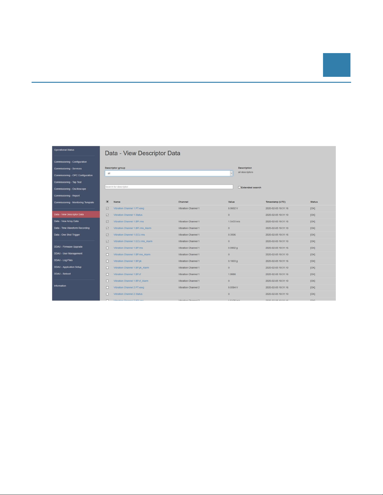
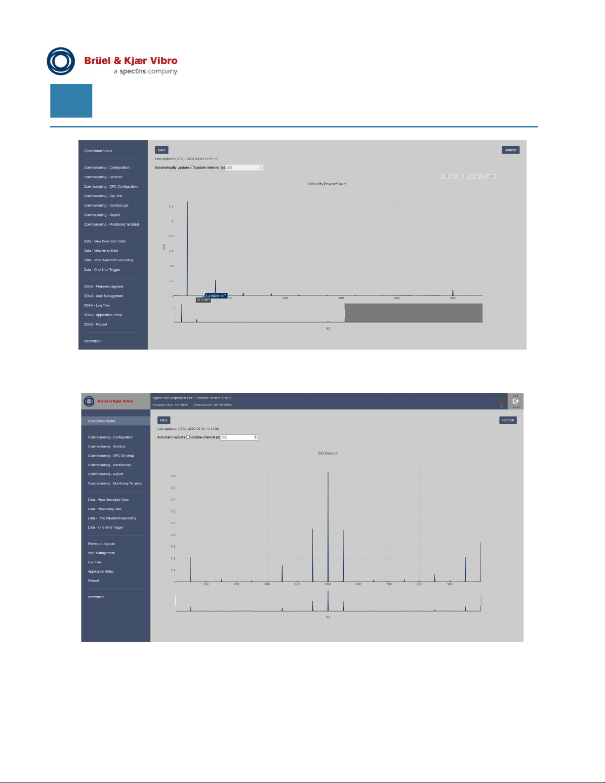
The configuration of VCM-3 is done via the VCM-3 Homepage. Apart from specific configuration the Homepage
offers on-line/on-site check of descriptors and frequency spectra. Figure 1 and 2 examples will illustrate this.
The Homepage access is controlled by user login with username and password.
Figure 1 VCM-3 Homepage: Data – View Descriptor Data (All data from all enabled channels will be continuously updated)
© Brüel & Kjaer Vibro ● C107757.002 / V02 Page 5 of 10
Technical alterations reserved!
Page 6
EN
Figure 2 VCM-3 Homepage: Data – View Array Data
(Example: FFT spectra derived from vibration velocity descriptor “BPi”)
Figure 3 VCM-3 Homepage: Data – View Array Data
(Example: Envelope spectra (SED) derived from acceleration enveloping descriptor “ECU”)
Page 6 of 10 © Brüel & Kjaer Vibro ● C107757.002 / V02
Technical alterations reserved!
Page 7
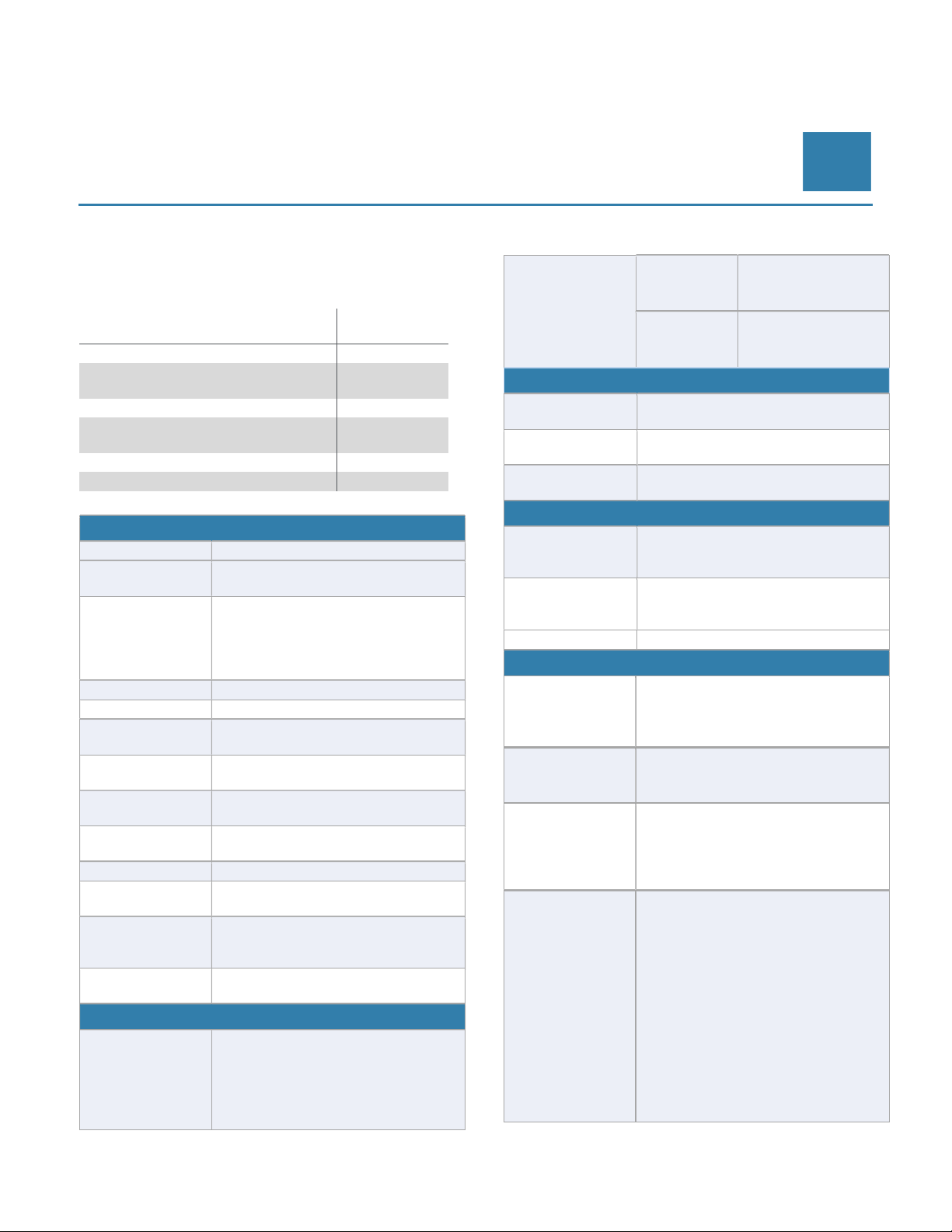
ADC
Frequency
Input Type
Dynamic Range
Interference
Accuracy
Accuracy
Distortion
Input Impedance
Rejection
Channels
Supply
Connections
protocol
functionality
Modbus RTU
Product specifications and ordering information
VIBRO Condition Monitoring 3 (VCM-3)
Technical Specification (device)
For additional information and instructions, refer to
the following companion documents:
Document/Description
VCM-3 Installation Instruction
Product specifications and
Ordering information
VCM-3 Safety (short) Instruction
VCM-3 On-Site Commissioning
Manual
VCM-3Homepage Manual
VCM-3 Editor Software Manual
12, AC/DC Analog Input Channels
24 Bit
Sampling
Analysis
Frequency
Range
Channel
204.8kHz synchronous on all
channels
0.1Hz - 80kHz
(ECU: 1kHz to 80kHz)
Lower to upper (filter) corner
frequency span minimum 1 : 3
but may not exceed 1 : 5000
Differential, bipolar (-25.5V to +25.5V)
> 100dB at 1kHz, > 94dB at 0.1kHz
>-100dB
Document
No.
C107758.002
C107757.002
C107761.001
C107759.002
C107760.002
C107762.002
EN
RMS (Accel. Vel.),
Detectors
Physical
Parameters
Networking
Network
Low level
Switch
OPC UA Server For data export to controllers, SCADA
Modbus TCP
Server
Secure protocols
3x (RJ45), 1x optical SFP connector
Ethernet TCP/IP, IPv4,
(prepared for IPv6)
4 network ports with built-in switch
functionality
System Integration
systems or other system components
(internal update rate 5 seconds)
For data export to SCADA systems or
other system components
(internal update rate 1 seconds)
(in preparation)
Cyber Security
Communication takes place through
secure and encrypted protocols, such
as Web-sockets, HTTPS, SCP.
Peak (Accel),
Crest factor (Accel.)
Acceleration, Velocity
AC Amplitude
DC Amplitude
Total Harmonic
Common Mode
Phase Match
Between
Sensor Power
Scalar Measurements (Descriptors)
Time Domain
Analysis
© Brüel & Kjaer Vibro ● C107757.002 / V02 Page 7 of 10
Technical alterations reserved!
±0.5dB
1% relative of full scale with ±40mV
Offset.
< 0.01%/250Hz/4Vpp
>100kΩ
>50dB at 50Hz
<0.3° at 80kHz
10mA/+24 Volt/ -24 Volt (external)
- Acceleration band pass
- Velocity band pass
(accel. integrated, ISO)
- ECU Envelope Condition
Unit
- Sensor Bias Voltage
Port
configuration
NERC
Compliance
Strong
passwords
All services using a TCP/IP port
(e.g. https, default port 443) can be
configured to use another port
The VCM-3 can be part of solutions
complying with NERC CIP Standards.
(North American Electric Reliability
Corporation – Critical Infrastructure
Protection).
The use of strong passwords is
enforced. Compliance with NIST
SP800-118 – Guide to enterprise
Password Management. Can be
changed by user.
Page 8
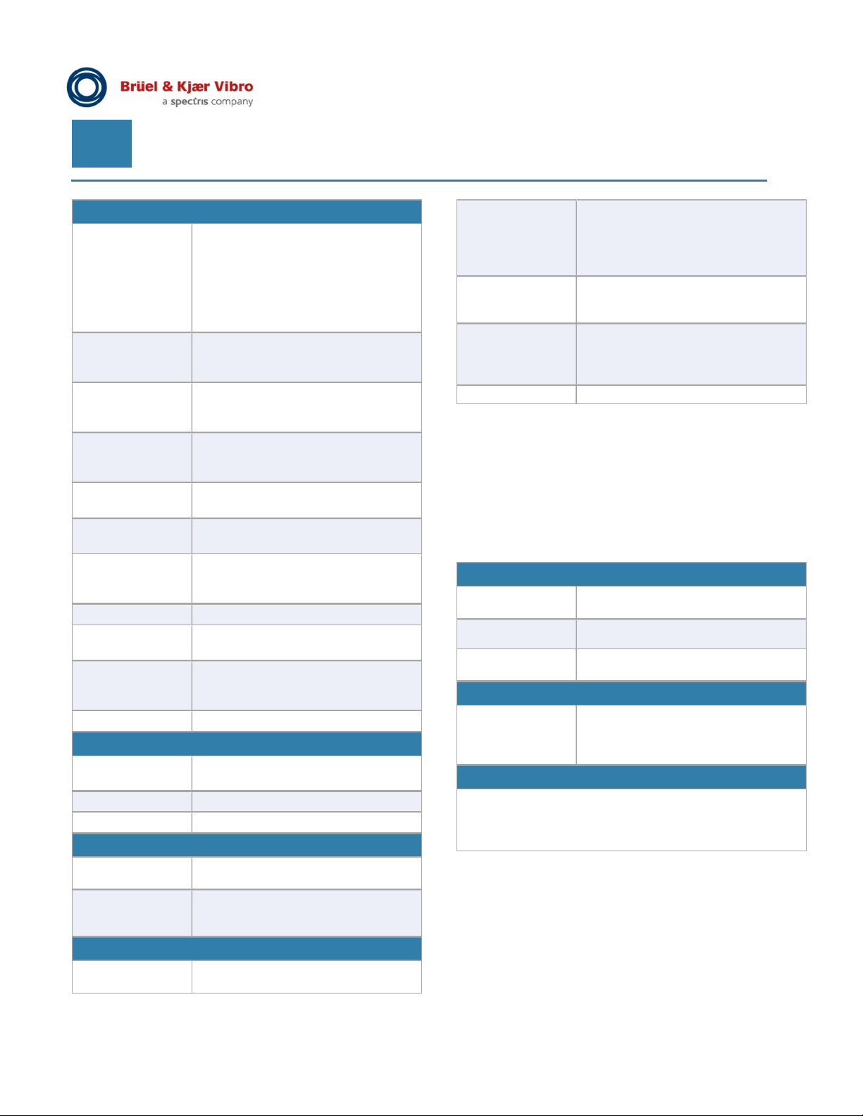
EN
Inclination
UL Certification
Weight
Consumption
operation
space
Ambient
Temperature
Ambient
Temperature
Temperature
Change
Static Damp
Heat, Cyclic
Damp Heat
Random & Sine
Vibration
Rough Handling
High Altitudes
IP Rating
HALT Test
Dimensions
Mounting
Voltage/Power
Fuses
Environmental
In operation. -30°C to +60°C (-22F to
+140F) in accordance to EN/IEC
60068-2-2. Applies to device and to
device mounted in cabinet.
-40°C (-40F) with reduced accuracy,
-70°C (-94F) with de-rated Mean Time
Between Failures (MTBF).
Storage. -40°C to +85°C (-40F to
+185F) in accordance to EN/IEC
60068-2-2
Operational during a temperature
change rate of 1°C per minute in
accordance to EN/IEC 60068-2-14
In operation. According to EN/IEC
60068-2-78, EN/IEC 60068-2-30 and
EN/IEC 60068-2-38
According to EN/IEC 60068-2-6.
Storage. According to
EN/ IEC 60068-2-31.
According to EN/IEC 60068-2-13. Air
pressure equivalent to 3500m
altitude.
According to IEC 60092-504.
The device IP rating is IP20 according
to EN/IEC 60529.
Has been subject to HALT test.
Excessive vibration and temperatures and combinations hereof
cULus certified (in preparation)
Mechanical
280 x 153.5 x 35 mm
(11,02 x 6,02 x 1,38 in)
1.5 kg (3,31 lbs)
DIN Rail Mounting or Wall mount
Power Supply
18-26 V DC/10W + power
consumption of each sensor.
Power supply inputs are fused to
protect against over-voltage and fire
VCM-3
Homepage
(embedded)
Calibration Factory calibrated.
Service
Design lifetime
For remote or local service.
Commissioning, view of trend and
array data, view Log files
(for re-calibration please contact B&K
Vibro)
No specific onsite service required.
VCM-3 has no moving parts, or other
parts which requires regular service
20 years
VCM-3 Editor (Software) PC and Software requirements
The VCM-3 Editor application allows adjustment of
the configuration parameters for Standard Monitoring
Templates provided with the software.
Hardware Requirements
Processor:
Main Memory
Required disk
Supported Operating Systems
Microsoft
Operating
System
For editing the VCM-3 Monitoring Template parameter a
spreadsheet editor is required. Excel 2010 or a newer
version is recommended, but other spreadsheet editors
capable of handling .xlsx files can be used as well
Intel 64 Bit or compatible
1GB
300 MB
Windows 10 (64 Bit)
Windows Server 2016 (64 Bit)
Additional Software
Fully remote
Page 8 of 10 █ © Brüel & Kjaer Vibro ● C107757.002 / V02
Technical alterations reserved!
Operational
Upload of firmware updates and
monitoring templates via network
Page 9
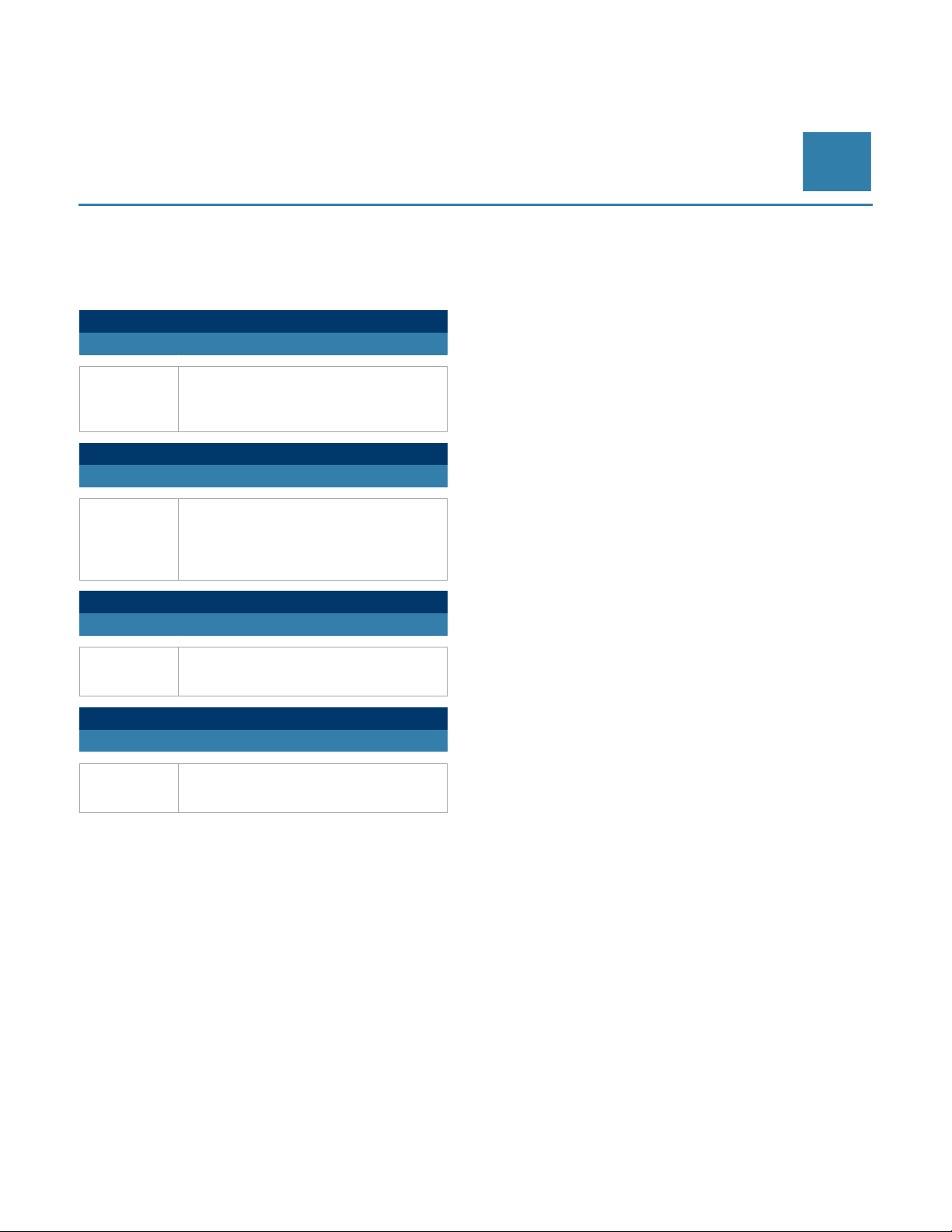
without mounting accessories.
(screwed on)
.
Product specifications and ordering information
VIBRO Condition Monitoring 3 (VCM-3)
Ordering Information
Use the following order codes when ordering a VCM3 device or associated accessories.
VCM-3 MONITOR (SPARE)
Order Code Description
“VIBRO Condition Monitoring 3” base
VCM-3
Order Code Description
VCM-3-DIN
Order Code Description
EA2039
Order Code Description
EP2136
monitor hardware type VCM-3.
1 to 12-channel monitoring system
VCM-3 MONITOR (DIN Rail)
“VIBRO Condition Monitoring 3” base
monitor hardware type VCM-3.
1 to 12-channel monitoring system
including two DIN- rail mounting clips
EA2039 DIN clip for VCM-3
2x DIN clip (set) including screws,
for mounting a VCM-3 to a DIN-rail
(One set required for one VCM-3).
EP2136 Adapter plate for VCM-3
1x stainless steel mounting plate
including screws for wall mounting a
VCM-3.
EN
© Brüel & Kjaer Vibro ● C107757.002 / V02 Page 9 of 10
Technical alterations reserved!
Page 10

Contact
Brüel & Kjær Vibro GmbH
Leydheckerstrasse 10
64293 Darmstadt
Deutschland
Phone: +49 (0) 6151 428 0
Fax: +49 (0) 6151 428 10 00
E-Mail: [email protected]
www.bkvibro.com
Document C107757.002 / V02 ●
Trademarks used herein are the property of their respective owners. Data and specifications subject to change without notice.
© 2020
Brüel & Kjær Vibro A/S
2850 Nærum – Denmark
Phone: +45 77 41 25 00
Fax: +45 45 80 29 37
BK Vibro America Inc
2243 Park Place, Suite A
Minden, Nevada 89423
USA
Phone: +1 (775) 552 3110
 Loading...