

Page 1
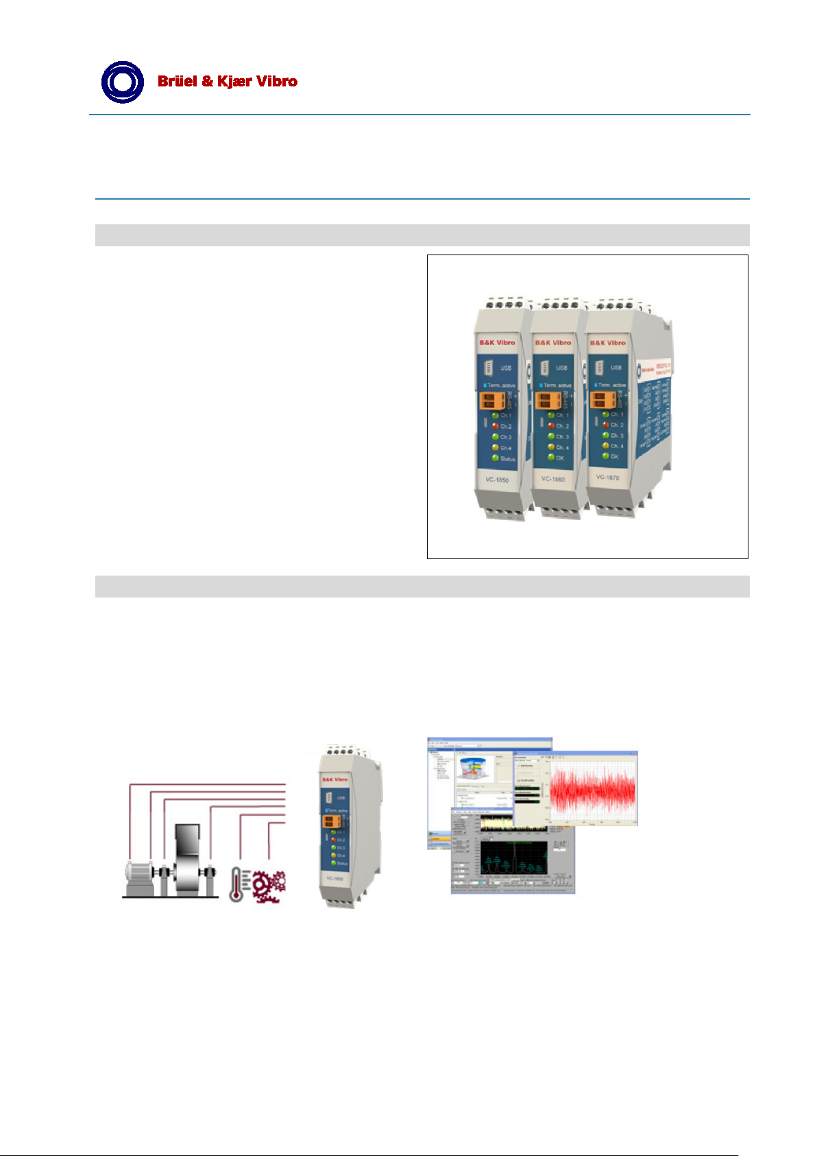
Features
enables cost
protection for all critical rotating
equipment with roller element bearing as well as
Product Specification
VIBROCONTROL 1800 Series
VIBROCONTROL 1800 Series
effective machine
sleeve bearings.
• 4-vibration channels, plus
• 2-channels process & speed
• extremely flexible with modular link concept
• time waveform recording and data storage
Dedicated solution via 3 types:
• VIBROCONTROL 1850
Acceleration Sensors (CCS)
• VIBROCONTROL 1860
Velocity Sensors
• VIBROCONTROL 1870
Displacement Sensors
Applications
VIBROCONTROL 1800 Series of Vibration Monitors are machine protection devices with 4 real-time vibration input
channels, 1 tacho input and 1 process input channel. These vibration monitors are combining protection with condition
monitoring of roller bearing machines, by means of a variety of bearing failure detectors like Envelope, Kurtosis and
Crest factor. VIBRONCONTROL 1800 offers 4-20 mA outputs, danger and alarm relays, a RS-485 and USB port for
communication and time waveform recording of RAW data. Several features support the ISO/EN 13849-1 standard.
Brüel & Kjaer Vibro GmbH Phone: +49 6151 428-1400 BPS155-EN-12
Leydheckerstrasse 10 Fax: +49 6151 428-1401 © Brüel & Kjaer Vibro
D-64293 Darmstadt E-Mail: [email protected] 07/2017 / Page 1 of 4
Technical alterations reserved!
Page 2

Product Specification VIBROCONTROL 1800 Series
Technical Data
6 Input channels:
• 4 configurable vibration sensor inputs:
VIBROCONTROL 1850 - accelerometers CCS
VIBROCONTROL 1860 - velocity sensors
VIBROCONTROL 1870 - displacement sensors
• 1 Input for process data, selectable
analogue 4-20 mA, 0-20 mA, 0-22V
• 1 Tacho input for NPN, PNP, AC speed sensor
Sensor types:
• VIBROCONTROL 1850
Accelerometers 10-500 mV/g, type CCS
Maximum input ±5.4 Vpk
Transducer Bias 5 mA
Input Resistance / Impedance ≥ 450 kΩ, 10 nF
• VIBROCONTROL 1860
Velocity sensors 50-100 mV/mm/s
Maximum input ±6.0/8.0 Vpk
Input Resistance / Impedance ≥ 450 kΩ, 5 nF
• VIBROCONTROL 1870
Displacement sensors 0.8-8 V/mm
Maximum voltage input -2 to -22 V
Peak detector, attack time 1-1,000 ms
Peak detector, decay time 0.1-100 s
Input Resistance / Impedance ≥ 450 kΩ, 10 nF
6 Measurement results per vibration
channel:
• 2 Overall vibration values
Detectors True RMS, Pk-Pk or Pk
Sample rates 4,800 or 24,000 Hz
Filter ranges 0.7 Hz to 10 kHz
Measuring parameter mm/s, m/s
• 4 Roller bearing condition units
Detectors True RMS, 2 Envelope
Filter ranges 1 - 500 Hz
Kurtosis/Crest factor acc. VDI 3832
2
, g, μm, mm
Up to 4 configurable outputs:
• 4 Analogue DC outputs
Can be configured as 0/4 - 20 mA, 0/2-10 V,
Each output can be assigned to any of the
measuring parameters.
Voltage load: min. 10 kΩ
Current load:. max. 400 Ω
or
• 4 Alarm relay drivers
Relay drivers for external coil: With breakfunction, can be user configured as Alert or
Danger with latch function or auto reset.
Max voltage 30 V
Max current: 100 mA
Alarm detectors:
• Alert and Danger per each detector with adjust-
able alarm limits.
Alert delay time 0 - 100 s
Danger delay time 0 - 100 s
Reset time for Alert and Danger 0 - 100 s
Up to 24 additional relays:
(VIBROCONTROL 1801)
• Up to 2 Relay Modules consisting of 12
galvanic isolated relays each. Alert and Danger
alarms can be directed to these relays.
Max voltage: 30 V
Max current: 100 mA
OK relay:
• 1 galv. isolated redundant relay with break-
function (power fail-safe). Danger alarms can
be forwarded to this relay, when the monitor is
configured as a Protection Monitor according to
ISO/EN 13849-1. All system failures, like cable
short, cable break and internal system failure,
will automatically trip the OK- relay.
EN
Configurable measuring ranges:
• Full scale vibration measuring ranges up to
1-100 mm/s,1-300 m/s
2
,0.1-15 mm Pk Pk
Standard frequency ranges:
• 10 Hz – 1,000 Hz, -1 dB, 24 dB/oct.
• Selectable ranges e.g. 1-300/1,000 Hz
or multiple filters settings 0.7-10,000 Hz
• Filter response High pass and low pass filters;
refer to the setup part for the specific
parameters for the Cut-off freq., pass band
attenuation, Stop band freq. and Stopband
attenuation.
Measurement accuracy:
• Vibration Measurement ±3.5% of reading
±0,5% of Full Scale setup, typical, @calibration
ref: 100Hz, velocity, 25 C, with current LP and
HP filter setup.
• Process Measurement ±0.75% of reading
±0.5% of Full Scale setup
• Speed sensors ±0.5% of reading,
Pulse speed 1Hz to 30kHz (RPM depending of
pulse per revolutions setup)
• Analogue output ±1.5% of reading
±1% of Full Scale
Page 2 of 4▐ © Brüel & Kjaer Vibro ● July 17 ● BPS0150-EN-12
Page 3
Product Specification VIBROCONTROL 1800 Series
Test function:
Can be activated digitally or by PC. As default the
alarm relays activate and DC outputs increase to
the specified test level of 102 %.
Front panel:
5 light diodes indicate channel status (green, yellow,
red) for each of the 4 vibration input channels, as
well as for general system status.
EN
Time waveform recording:
Up to 4 input channels can record digital raw data
(time waveform) simultaneously to a PC running
"Commpact Analyzer". The recording can be done
through:
RS-485/LAN (buffered) Up to 10 kHz
Mini USB (real-time) Up to 10 kHz
Time waveform recording is user activated and contains scalar values for vibration and process input
data at start of recording.
Data storage:
(VIBROCONTROL 1803 /1804)
All input channels can be trended and alarms can
be stored when connected to either EtherBridge or
directly to a PC running “Compact Analyzer”.
VIBROCONTROL 1804 EtherBridge RAM can store
trends and time wave-form recordings event or timer
based.
Communication:
RS-485 interface 2 screw terminals
Daisy chain, up to 255 units
USB interface: Mini USB/B
Remote access through EtherBridge Module
(VIBROCONTROL 1803) is possible.
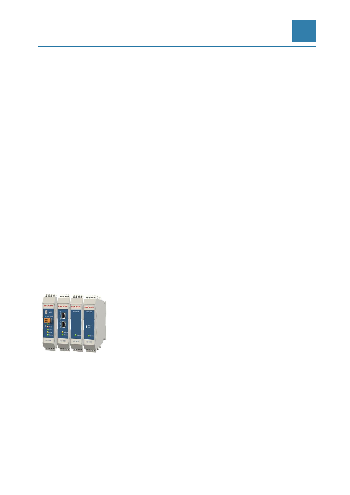
Link Concept modularity:
VIBROCONTRL 1800 Series –all components Vibration Monitor, EtherBridge, Relay Module, Input
and Output Modules can be interconnected by
means of DIN rail bus connectors
Temperature:
• Operating: -10 °C to +50 °C
• Storage: -40 °C to +85 °C
Housing:
DIN rail enclosure IP20 with screw terminals
• Dimensions: H: 110, W: 23, D: 114 mm
• Weight (measuring module): 160 g
Compliance:
• CE, ISO 13849-1, ISO 10816-3, VDI 3832,
API 670
Accessories:
• External Power supply (e.g. AC-4111)
+24 V DC, ±5 %,
max. power consumption; 10 W
© Brüel & Kjaer Vibro ● July 17 ● BPS0150-EN-12 Page 3 of 4▐
Page 4

Product Specification VIBROCONTROL 1800 Series
Ordering Information
VIBROCONTROL 1850
Vibration monitoring unit for accelerometer input Order Code: VC-1850
Standard Accelerometer AS-062 (CCS) Order Code: AS-062
VIBROCONTROL 1860
Vibration monitoring unit for velocity sensor input Order Code: VC-1860
Standard velocity sensor VS-068 (horiz.) or VS-069 (vert.) Order Code: VS-068
VS-069
VIBROCONTROL 1870
Vibration monitoring unit for displacement sensor input Order Code: VC-1870
Please find alternative sensors out of B&K Vibro´s large portfolio.
Additional modules within the VIBROCONTROL 1800 series – Link Concept
VIBROCONTROL 1801 Relay Module
for DIN Rail installation incl. 12 potential free relays 30V Order Code: VC-1801
VIBROCONTROL 1803 Ethernet-Bridge
incl. RS485, shared RS485/RS232 and LAN Order Code: VC-1803
VIBROCONTROL 1804 Ethernet-Bridge & Data Logger
incl. 4 GB RAM Order Code: VC-1804
EN
Compact Commander Software for Configuration & Diagnostics
Compact Setup - Configuration Software for all VIBROCONTROL 18xx modules included in delivery
Compact Analyzer - Analyzing Software for stored measuring data on request
Optional: Accessories
Power Supply 24 VDC
Type: DSP 10-24; 230VAC / 24 VDC, 10 W Order Code: AC-4111
Field Housing for VIBROCONTROL 1800 components
Fibox, Polycarbonat AC-2131 on request
Field Housing for VIBROCONTROL 1800 components
IP67, Aluminium AC-2132 on request
Field Housing for VIBROCONTROL 1800 components
metal AC-2133 on request
© Brüel & Kjaer Vibro ● July 17 ● BPS0150-EN-12 Page 4 of 4▐
 Loading...