

Page 1
Instruction
VIBROCONTROL 1800 Series
Four channel vibration monitors
VC-1850 Accelerometers
VC-1860 Velocity Sensors
VC-1870 Displacement Sensors
Extension Modules:
VC-1801 additional relays
VC-1803/04 communication and data storage
Keep it accessible for future reference
Page 2

Page 3

Copyright © 2018 Brüel & Kjaer Vibro GmbH
All rights to this technical documentation remain reserved.
Any corporeal or incorporeal reproduction or dissemination of this technical documentation or making this
document available to the public without prior written approval from Brüel & Kjaer Vibro GmbH shall be
prohibited. This also applies to parts of this technical documentation.
Brüel & Kjaer Vibro GmbH
Leydhecker Str. 10
64293 Darmstadt
Germany
Phone: +49 6151 428 0
Fax: +49 6151 428 10 00
E-Mail: [email protected]
Hotline:
Phone: +49 6151 428 1400
E-Mail: [email protected]
Page 4

EN
Content
1 Applications 7
2 VIBROCONTROL 1800 Series Types 8
2.1 VIBROCONTROL 18xx module layout 9
2.2 VIBROCONTROL 1850 (Accelerometer CCS) 9
2.3 VIBROCONTROL 1860 (Velocity Sensors) 10
2.4 VIBROCONTROL 1870 (Displacement Sensors) 10
3 Hints for safe operation of VIBROCONTROL 18xx devices 11
4 Getting started 13
4.1 Connecting the VIBROCONTROL 18xx 13
4.2 Cable Connections 15
4.3 Powering and Start-up 15
5 Functionality 16
5.1 General for VIBROCONTROL 1850 16
5.2 Features of VIBROCONTROL 1850 17
6 Setup and Operation of VIBROCONTROL 18xx 19
6.1 General 19
6.2 View “Monitor” 19
6.3 Self-Test 20
6.4 Output selection (4-20 mA or Relay) 21
6.5 Sensors 22
6.6 VIBROCONTROL 1850: Setup of Band 1 and Band 2 24
6.7 VIBROCONTROL 1850: Setup of the Envelope 1 and Envelope 2 detectors 25
6.8 Bearing Frequency calculator 27
6.9 Crest Factor 30
6.10 Kurtosis 31
6.11 Process input (VC-1870 input for axial position) 32
6.12 Speed Sensor (Tacho) input 33
6.12.1 Speed sensor selection 35
6.13 Alert and Danger alarms 35
6.14 System Failure (OK) 36
6.15 Alarm Hang Time 37
6.16 Overload, Cable Short and Cable Break 37
6.17 Over range 38
6.18 Output configuration 38
Page 4 of 84
Technical alterations reserved!
█ © Brüel & Kjaer Vibro ● July 2018 ● C106834.002 / V02
Page 5

© Brüel & Kjaer Vibro │Instruction VC-1800 series Applications
EN
6.18.1 Relays 38
6.18.2 Analog outputs 39
6.19 Light Emitting Diodes (LEDs) 40
6.20 Reset of Alarms 41
6.21 Inhibit Alarms 41
7 VIBROCONTROL 1870 - Displacement measurement 42
7.1 VIBROCONTROL 1870 – 4-channel - relative shaft vibration 42
7.2 VIBROCONTROL 1870 – Axial shaft position 45
8 Extension Modules for VIBROCONTROL 1850/1860/1870 47
8.1 VIBROCONTROL 1801 Relay Module- 12 relays 47
8.1.1 General 47
8.1.2 VIBROCONTROL-1801 Relay Module 47
8.1.3 Make/Break of relays 47
8.1.4 Mounting 48
8.1.5 External connections 48
8.1.6 Front panel status LED 49
8.1.7 Configuration of VC-1801 using the Compact Setup Software 49
8.1.8 Connecting of a VIBROCONTROL 18xx and a VC-1801 50
8.2 VIBROCONTROL 1803/1804 Communication Module - Etherbridge 51
8.2.1 Network 51
8.2.2 Applications 52
8.2.3 Features 52
8.2.4 Functionality 53
8.2.5 Configuration of VIBROCONTROL 1803/1804 55
8.2.6 VIBROCONTROL 1803/04 with Compact Setup 62
9 Connecting the VIBROCONTROL 18xx to a PLC/PC 65
9.1 USB 2.0 interface 65
9.2 RS-485 interface 65
9.3 VIBROCONTROL 1803/04 LAN interface 66
9.4 Modbus Connection for VIBROCONTROL 18xx via 1803/04 Modbus Address and Register66
10 Mounting/installation of the VIBROCONTROL 18xx 72
10.1 Assembly / disassembly of the device: 72
10.2 Terminal marking 72
10.3 Installation 74
10.3.1 Sensor connection 74
10.3.2 Analog outputs 75
10.3.3 Power Supply 75
10.4 Powering and Start-up 76
© Brüel & Kjaer Vibro ● July 2018 ● C106834.002 / V02 ● █ Page 5 of 84
Technical alterations reserved!
Page 6

EN
10.5 DIN-rail bus module connection 76
11 Technical data 77
12 Maintenance 81
12.1 Cleaning 81
13 Disassembly and Disposal 81
14 Appendix A: Backup Battery PSDS 82
Page 6 of 84
Technical alterations reserved!
█ © Brüel & Kjaer Vibro ● July 2018 ● C106834.002 / V02
Page 7
© Brüel & Kjaer Vibro │Instruction VC-1800 series Applications
W
ARNING!
This symbol warns of dangerous situations, which can result from misuse of the product.
EN
NOTE!
This symbol provides general and useful information for using the product.
1 Applications
The VIBROCONTROL 18xx Vibration Monitor is maintenance free device mounted in a DIN rail enclosure. It is
used to monitor vibration parameters and protect machines like pumps, blowers, ventilators, decanters,
separators, centrifuges, mills and milling equipment.
The VIBROCONTROL 18xx Vibration Monitor continuously keep track of the vibration level in maximum four
measuring points in each of which an external sensor is positioned. In addition, the VIBROCONTROL 18xx also
have one Tachometer Input for machine speed detection and synchronization, as well as one Process Input for
measuring a pressure or a temperature, or similar.
With the help of a PC, having the Compact Setup Software installed, it is possible to read-out the different
vibration parameter levels and status information. In addition, the use of this software enables the possibility to
carry out a remote parameter setup of one device (at the time) out of a number of VIBROCONTROL 18xx
devices.
The VIBROCONTROL 18xx also includes an USB interface for direct access from PC to the VIBROCONTROL
18xx device on a point-to-point basis. The USB interface is used if the device is not connected to a fieldbus,
LAN or if the data transmission speed (= Baud rate) with RS-485 is slow.
© Brüel & Kjaer Vibro ● July 2018 ● C106834.002 / V02 ●
Technical alterations reserved!
█
Page 7 of 84
Page 8

EN
Pre-Release
2 VIBROCONTROL 1800 Series Types
VIBROCONTROL 1800 Series enables cost effective protection for all critical rotating equipment with rolling
element bearings as well as sleeve bearings.
Dedicated solutions via these three basic independent protection units:
VIBROCONTROL 1850
Acceleration Sensors (CCS)
VIBROCONTROL 1860
Velocity Sensors
4-vibration channels for case vibration (CV)
1-channel process data (4-20 mA)
1-channel speed
VIBROCONTROL 1870
Displacement Sensors
4-vibration channels for relative shaft vibration (RSV)
1-channel axial position (trust position)
1-channel speed
Extension modules
VIBROCONTROL 1801
Relais Module (12 Relais)
VIBROCONTROL 1803 / 1804
Communication Modules / Ethernet Bridge / Data storage
Page 8 of 84
Technical alterations reserved!
█ © Brüel & Kjaer Vibro ● July 2018 ● C106834.002 / V02
Page 9
© Brüel & Kjaer Vibro │Instruction VC-1800 series VIBROCONTROL 1800 Series Types
p
(
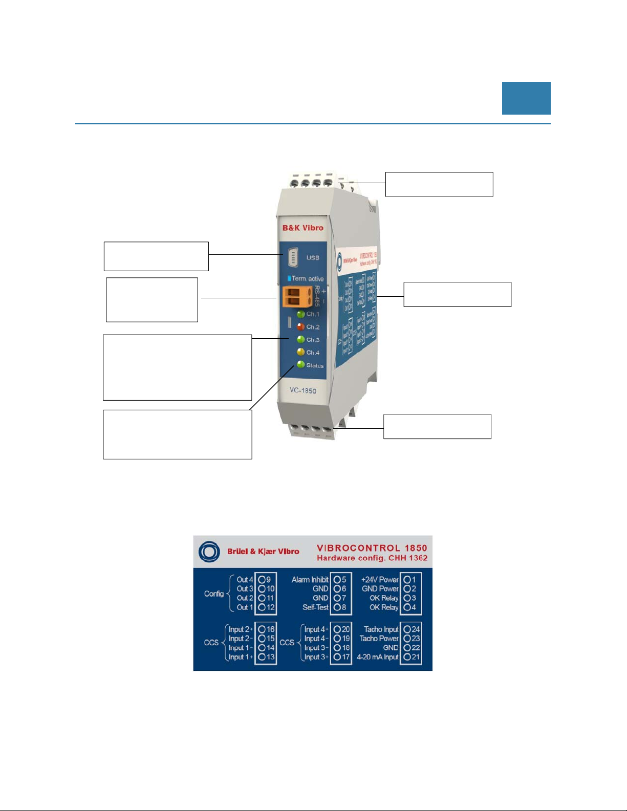
2.1 VIBROCONTROL 18xx module layout
Terminals
USB for data transfer
& setu
EN
RS-485 for Modbus
connection & data
transfer
Channel status:
Green (below Alarm level)
Yellow (Alert)
Red (Danger)
System Status
Green (OK)
Red
NOK)
Terminals
2.2 VIBROCONTROL 1850 (Accelerometer CCS)
Terminal Configuration
Terminal Configuration
© Brüel & Kjaer Vibro ● July 2018 ● C106834.002 / V02 ● █ Page 9 of 84
Technical alterations reserved!
Page 10
EN
Pre-Release
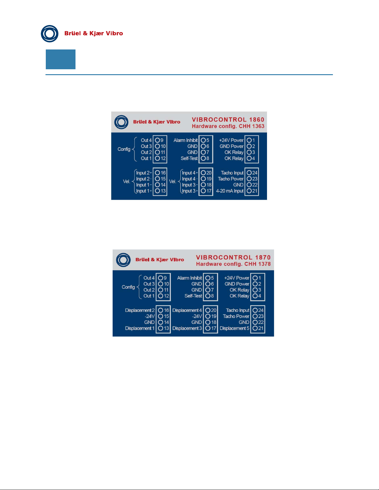
2.3 VIBROCONTROL 1860 (Velocity Sensors)
Terminal Configuration
2.4 VIBROCONTROL 1870 (Displacement Sensors)
Terminal Configuration
Please note displacement sensor input 1-4 is used for relative shaft vibration; displacement 5 is used for axial
position only.
Page 10 of 84
Technical alterations reserved!
█ © Brüel & Kjaer Vibro ● July 2018 ● C106834.002 / V02
Page 11
© Brüel & Kjaer Vibro │Instruction VC-1800 series
Hints for safe operation of
VIBROCONTROL 18xx devices
EN
3 Hints for safe operation of VIBROCONTROL 18xx devices
Safety:
This User Manual contains information, which should be followed by the user in order to ensure safe operation.
If the VIBROCONTROL 1800 Monitors develops a fault, switch it off and secure it against
unintended use.
General:
Please carefully read the operating instructions prior to set-up of the device. Make sure that your
VIBROCONTROL 18xx device is suitable for your application without any restrictions.
Improper use:
Any improper or non-intended use may lead to malfunctions of the VIBROCONTROL 18xx device or to
unwanted effects in your application. If the VIBROCONTROL 18xx is used in a way not described in the
relevant user manuals, function and protection may be impaired and serious personal damage, death or
serious, irreversible injuries may result.
Installation and operation:
Installation, electrical connection, set-up, operation and maintenance of your VIBROCONTROL 18xx device(s)
must only be carried out by qualified/trained personnel (electrician) authorized by the machine operator in
accordance with local- and national regulations for the installation of electrical equipment.
Changing the setup parameters:
Before applying a new set of setup parameters to the VIBROCONTROL 18xx device, please make sure that
doing so cannot cause any damage to persons and/or machinery.
Connecting the sensor(s):
Please make sure to meet the safe extra-low voltage (SELV) criteria when any sensors are connected to the
VIBROCONTROL 18xx device so that no dangerous contact voltages are applied to the sensor and/or
transferred to the device. The sensor and the power supply of the VIBROCONTROL 18xx device are not
galvanic isolated.
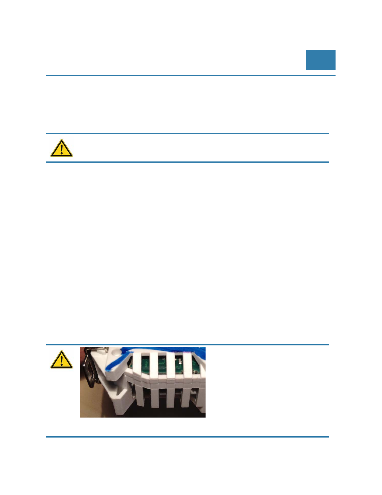
Electromagnetic compatibility (EMC)
The VC-18xx complies with the relevant
of ventilation slots.
Electrostatic discharges in this area can destroy the device.
requirements of the Electromagnetic
Compatibility Directive 2014/30 / EU. The EMC
has been tested according to EN 61326-1, with
the reduction of the requirement for static
electricity (ESD).
When handling the VC-18xx, attention must be
paid to protective measures against electrostatic
discharge. This applies in particular to the area
© Brüel & Kjaer Vibro ● July 2018 ● C106834.002 / V02 ●
Technical alterations reserved!
█
Page 11 of 84
Page 12

EN
Pre-Release
Sensor cable mounting:
To prevent negative effects on the functioning of the VIBROCONTROL 18xx device caused by noise voltages,
please lay shielded sensor cables and load cables separately.
Cable break, cable short and sensor overload:
For a detailed description of how a VIBROCONTROL 18xx device reacts to a shortening/breakage of the
sensor cable or an overload of the sensor signal, please read section 6.16 of this manual.
Ingress protection:
The VIBROCONTROL 18xx has an ingress protection of IP20. The VIBROCONTROL 18xx device must be
mounted in a control cabinet with an ingress protection of at least IP54. The control cabinet should be installed
in accordance with local- and national rules and regulations.
Mounting:
Mount the VIBROCONTROL 18xx device on a 35 mm DIN rail inside the control cabinet. Mount the device
vertically but make sure to leave enough space between the unit and the top and/or bottom of the control
cabinet. Only this way the air circulation will be sufficient to avoid excessive heating of the device.
Connecting to a power supply:
The VIBROCONTROL 18xx device has a voltage tolerance of +24 VDC ±5 %
Before connecting the VIBROCONTROL 18xx device to a +24 VDC supply voltage, please make sure that all
terminal blocks are completely inserted.
The external +24 VDC supply voltage must be generated and supplied according to the SELV requirements.
Protect the +24 VDC supply voltage externally with max. 2A.The ground (GND) of the DC supply is directly
connected with the ground (GND) of the sensor supply, if any. The SELV criteria must therefore be met for the
DC supply (safety extra-low voltage, circuit electrically isolated from other circuits, not grounded). If the DC
circuit is to be grounded (e.g. due to national regulations), the protective-extra-low-voltage (PELV) criteria must
be adhered to (SELV with circuit galvanic isolated from other circuits).
Maintenance:
If used correctly no maintenance and repair measures are necessary. Only the manufacturer is allowed to
repair the unit.
Page 12 of 84
Technical alterations reserved!
█ © Brüel & Kjaer Vibro ● July 2018 ● C106834.002 / V02
Page 13
© Brüel & Kjaer Vibro │Instruction VC-1800 series Getting started
EN
4 Getting started
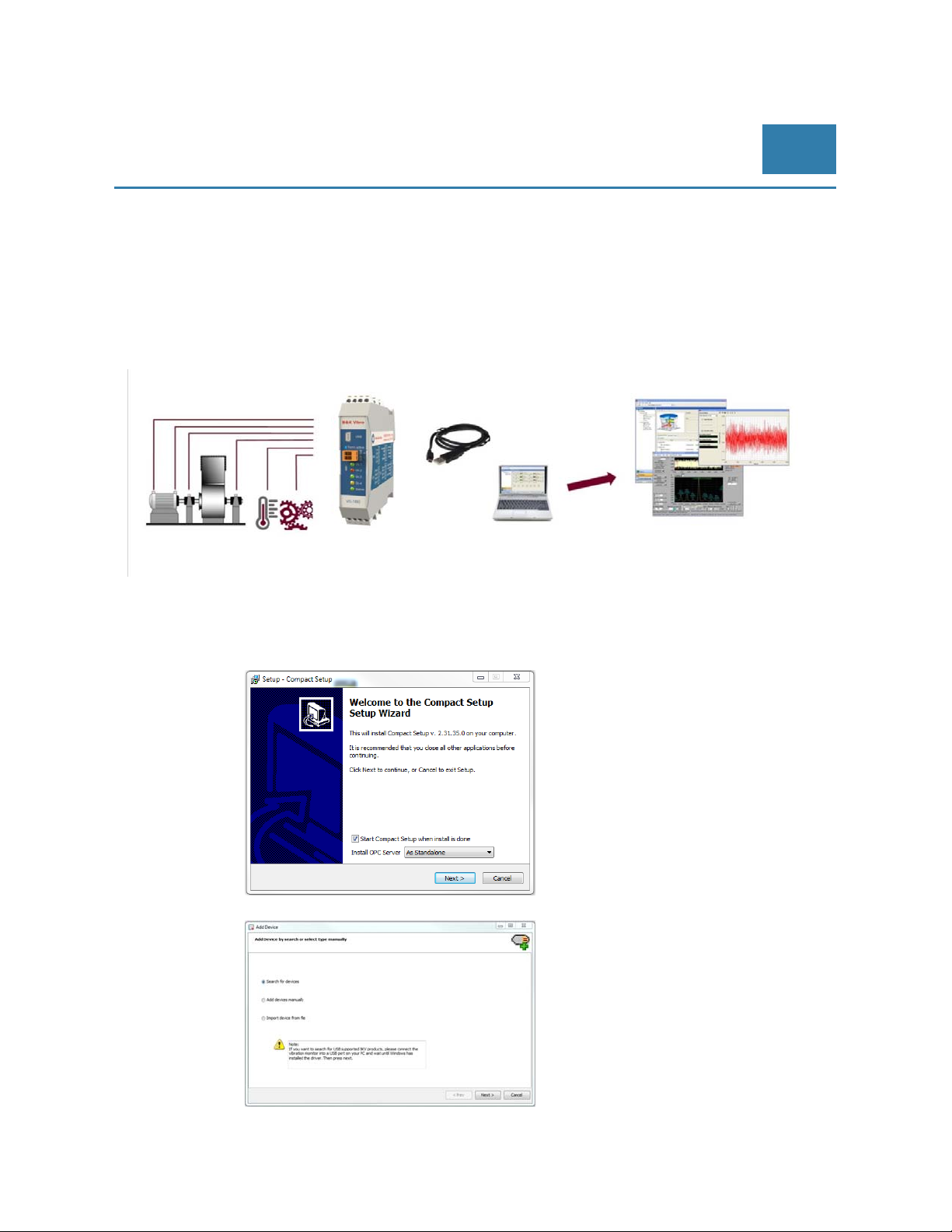
Connect the VIBROCONTROL 18xx to a (notebook) PC with the Compact Setup Software installed, using
one of its interfaces (USB, RS-485 or LAN via VIBROCONTROL 1803 Ethernet-Bridge) with the appropriate
cable.
4.1 Connecting the VIBROCONTROL 18xx
Figure 4-1) Connection picture
Install the Compact Setup Software from the CD.
Follow the installation wizard
In the Add Device window, please
choose “Search for devices”
(= automatic search).
© Brüel & Kjaer Vibro ● July 2018 ● C106834.002 / V02 ● █ Page 13 of 84
Technical alterations reserved!
Page 14
EN
Pre-Release
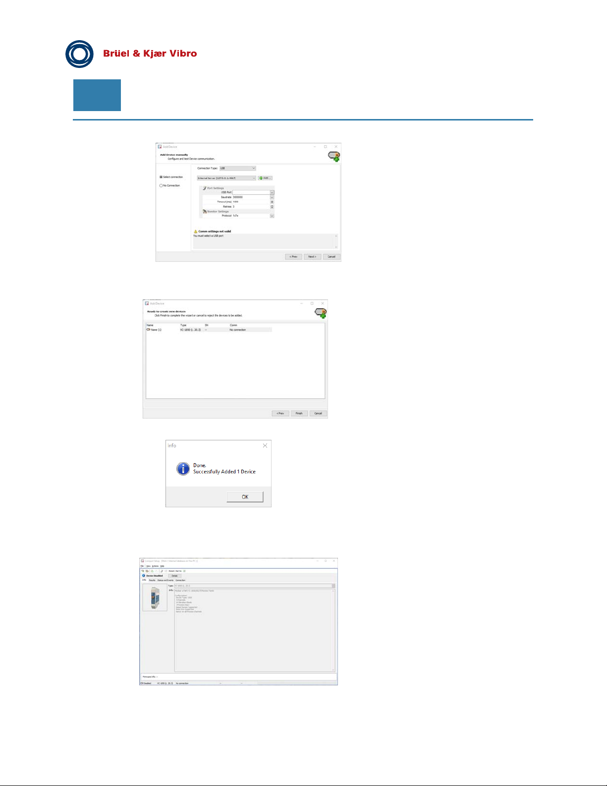
Successful search will result in a
VIBROCONTROL 18xx with a serial
number (S/N).
Click on “Next”.
Click on “Finish” to end the search.
The information at the right
indicates that your
VIBROCONTROL 18xx is
successfully connected to the
PC.
Click on “OK” to get to the
Compact Setup Software main
window.
Find your VIBROCONTROL 18xx
device in the listing of devices at the
left side of the main window.
Page 14 of 84
Technical alterations reserved!
█ © Brüel & Kjaer Vibro ● July 2018 ● C106834.002 / V02
Page 15

© Brüel & Kjaer Vibro │Instruction VC-1800 series Getting started
4.2 Cable Connections
Connect the different terminals on the VIBROCONTROL18xx in the following sequence:
Sensor input at terminals #13 to #20. If required, please observe polarity.
Relay(s) relative to GND, current and/or voltage output(s) at terminals #9 to #12.
Tacho power and Tacho Input signal terminals #23 and #24.
Process input (relative to GND) at terminals #21 and #22.
(VIBROCONTROL 1870: This input is used for axial position measurement)
Highly reliable redundant (= 2x) Failure galvanic insulated relay(s) at terminals #3 and #4.
Main Power (+24 VDC) and ground (GND) at terminals #1 and #2.
Optional external connection to terminals #5 and #8 to initiate respectively “Alarm Inhibit” or
Self-Test by connecting these terminals to ground.
Connect the VIBROCONTROL18xx to a PC so that communication between these two devices
can be established. For communications, the VIBROCONTROL 18xx has RS-485 and
USB interfaces. Optional it is possible to communicate via a LAN connection using a
VIBROCONTROL 1803 Ethernet-Bridge module.
4.3 Powering and Start-up
EN
After connecting to Power or changing setup the instruments is proceeding a startup program, which is
indicated by red, or blinking Channel LEDs and/or blinking OK LEDs. This procedure takes up to 30 seconds. In
case there is no violation of alert and danger levels or any OK failure, all LEDs should turn to green.
© Brüel & Kjaer Vibro ● July 2018 ● C106834.002 / V02 ● █ Page 15 of 84
Technical alterations reserved!
Page 16
EN
Pre-Release
5 Functionality
5.1 General for VIBROCONTROL 1850
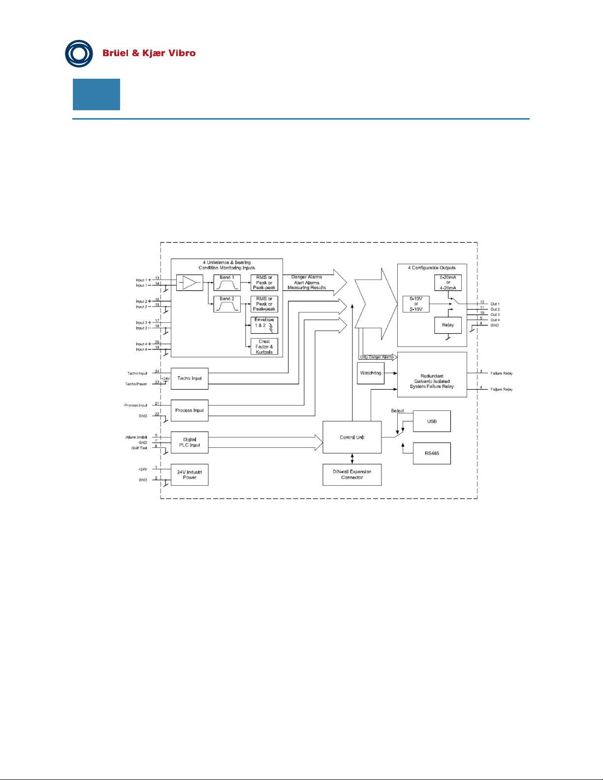
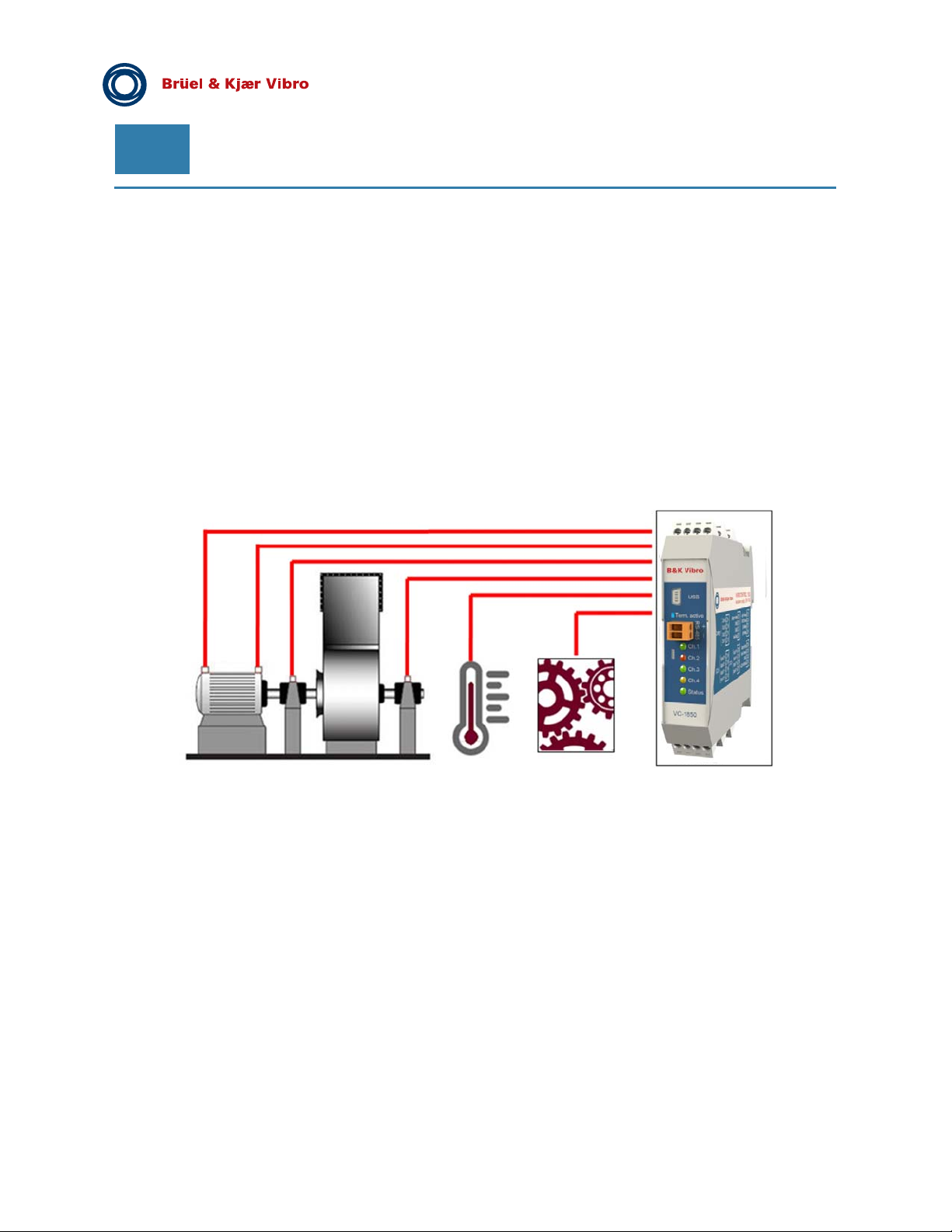
The VIBROCONTROL 1850 Vibration Monitor has four 2-wire CCS accelerometer inputs.
Page 16 of 84
Technical alterations reserved!
█ © Brüel & Kjaer Vibro ● July 2018 ● C106834.002 / V02
Page 17
© Brüel & Kjaer Vibro │Instruction VC-1800 series Functionality
EN
5.2 Features of VIBROCONTROL 1850
The VIBROCONTROL 1850 Vibration Monitor is a device with four sensor input channels, each having two
independent bands (Band 1 and Band 2) with the following specifications:
Band 1 and Band 2:
Full scale in True RMS, Peak or Peak-to-Peak values of the momentary vibration parameters
acceleration (m/s
Many band-pass filters within the ranges:
Band 1
0.1 to 1500.0 Hz or 5.0 to 11500.0 Hz; 10 Hz – 1000 Hz
Band 2
2 kHz – 10 kHz
Alert and Danger alarm limits can be configured.
Default setup
Alert is 7.1 mm/s
Danger 11.0 mm/s.
Band 2 (only):
Two separate envelope detectors. Each envelope detector has its own band-pass filter. Each
envelop analyser has its own Alert and Danger alarms.
Crest factor detector with Alert and Danger alarms
Kurtosis detector with Alert and Danger alarms
2
), velocity (mm/s) or displacement (µm);
General for All VIBROCONTROL VC-18xx:
Each vibration parameter may have an individual alert and/or danger alarm trigger level
assigned. If an alert and/or danger alarm is activated, the associated channel LED(s) at the front
of the enclosure will illuminate:
Green = No alarm, Yellow = Alert alarm and Red = Danger alarm
The Alert and/or Danger alarms can be configured as “Low Level” or “High Level” alarms
The Alert and/or Danger alarms can be latched individually.
Four independent configurable outputs (terminals #9, #10, #11 and #12) that can be assigned to
any Alert or Danger alarm. Each of the outputs may have any (but only one at the time) of the
following functions:
~ Solid-state relay. When activated the relay will “break”, the corresponding enabled alarm
relay(s) will become activated and thereby inform the user, e.g. via a connected rotor light,
beeper, PLC or by directly shutting down the machine.
~ Analog dc current output : 0-20 mA or 4-20 mA; The default is 4-20 mA
~ Analog dc voltage output : 0-10 V or 2-10 V
An internal watchdog continuously monitors the functionality of the complete monitor. When a
non-critical system failure is detected, the „OK“ LED at the front of the enclosure lights Red.
In case of the occurrence of a critical system failure, the same LED flash Red instead. Using two
mechanical relays in series for the same event adds redundancy to the system failure output and
thus considerable increases the reliability that a system failure alarm will be detected.
© Brüel & Kjaer Vibro ● July 2018 ● C106834.002 / V02 ● █ Page 17 of 84
Technical alterations reserved!
Page 18
EN
The VIBROCONTROL 18xx Vibration Monitor is provided with a RS-485 and an USB interface, which allow it to
to connect it to a PLC or to be configured from a PC.
Using a VIBROCONTROL 1803 Ethernet-Bridge enables remote communication via a LAN cable.
Possibility to start a complete self-test of the vibration monitor by connecting the “Self-Test”
terminal #8 to ground. A flashing Yellow „OK“ LED at the front of the enclosure indicates an
ongoing self-test.
Possibility to inhibit (all) alarms by assigning the “Alarm Inhibit” digital I/O terminal #5 on the
enclosure to ground
A Process input (terminal #21) can be used to analyse an analog current (0-20 mA) or voltage
(0-10 VDC) input signal.
A tachometer input (terminal #24).
Pre-Release
Page 18 of 84
Technical alterations reserved!
█
© Brüel & Kjaer Vibro ● July 2018 ● C106834.002 / V02
Page 19
© Brüel & Kjaer Vibro │Instruction VC-1800 series
Setup and Operation of
VIBROCONTROL 18xx
EN
6 Setup and Operation of VIBROCONTROL 18xx
6.1 General
The setting of the measuring parameters of the VIBROCONTROL 18xx can be carried out with Compact Setup
Software:
It is possible to change one or more setup parameter. The change of VIBROCONTROL 18xx
setup parameters can only be carried out for one device at the time.
The measuring parameter setup for channels with an accelerometer (CCS) VIBROCONTROL 1850 or a
velocity sensor VIBROCONTROL 1860 is very much similar.
6.2 View “Monitor”
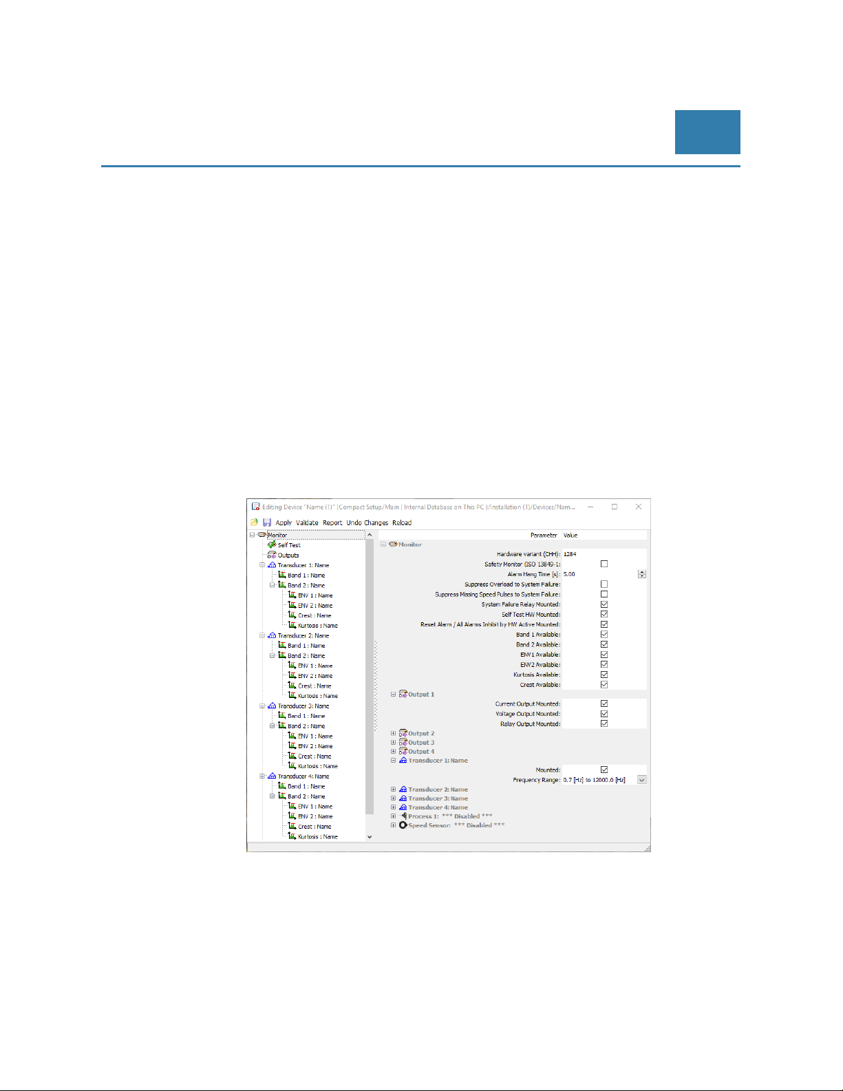
In the Compact Setup Software “Monitor” page it is possible to see those features/functions that are available
for use.
© Brüel & Kjaer Vibro ● July 2018 ● C106834.002 / V02 ● █ Page 19 of 84
Technical alterations reserved!
Page 20
EN
Pre-Release
6.3 Self-Test
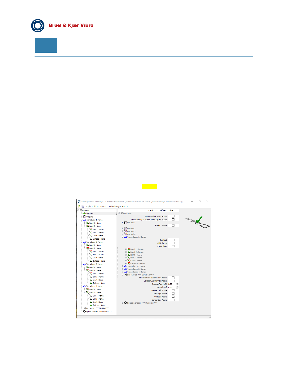
The VIBROCONTROL 18xx includes a “Self-Test” function that can be activated externally by connecting a
ground (GND) signal to terminal #8 on the enclosure. Alternatively the self-test can be activated using the
Compact Commander Software.
Only individual functions/features can be addressed during a self-test. But there are NO consequences, i.e. no
alarms will be triggered if a certain vibration level set during self-test exceeds an alarm trigger level. If an alarm
must be triggered during self-test the alarm in question must be marked. The behaviour of outputs during a selftest must also be specified separately.
Thus, the user will have to specify/set the following in connection with a self-test:
The measurement result scalar level for each vibration parameter in its own units, e.g. mm/s.
The status of alarms during a self-test.
All four outputs, either as a status of relays or a certain scalar level of
○ dc current (mA) or
○ dc voltage (V).
The Process Input must be specified in detail, i.e. signal scalar levels and alarms.
For the duration of thy self-test the „OK“ LED will flash Yellow.
Page 20 of 84
Technical alterations reserved!
█ © Brüel & Kjaer Vibro ● July 2018 ● C106834.002 / V02
Page 21
© Brüel & Kjaer Vibro │Instruction VC-1800 series
Setup and Operation of
VIBROCONTROL 18xx
EN
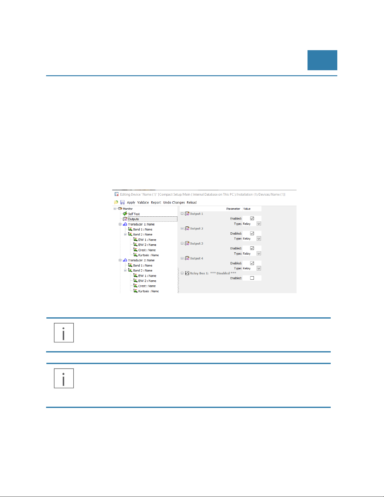
6.4 Output selection (4-20 mA or Relay)
The VIBROCONTROL 18xx has four configurable outputs at terminals #9, #10, #11 and #12. Each of the
available outputs can be enabled or disabled.
An enabled output can have any of five output functions:
A solid-state relay, which is closed and connected to ground (GND) when not activated. When
activated the relay breaks.
An analog dc current output of 0-20 mA or 4-20 mA, direct proportional to the measured
parameter between 0 and full scale.
An analog dc voltage output of 0-10 Volt or 2-10 Volt, direct proportional to the measured
parameter between 0 and full scale.
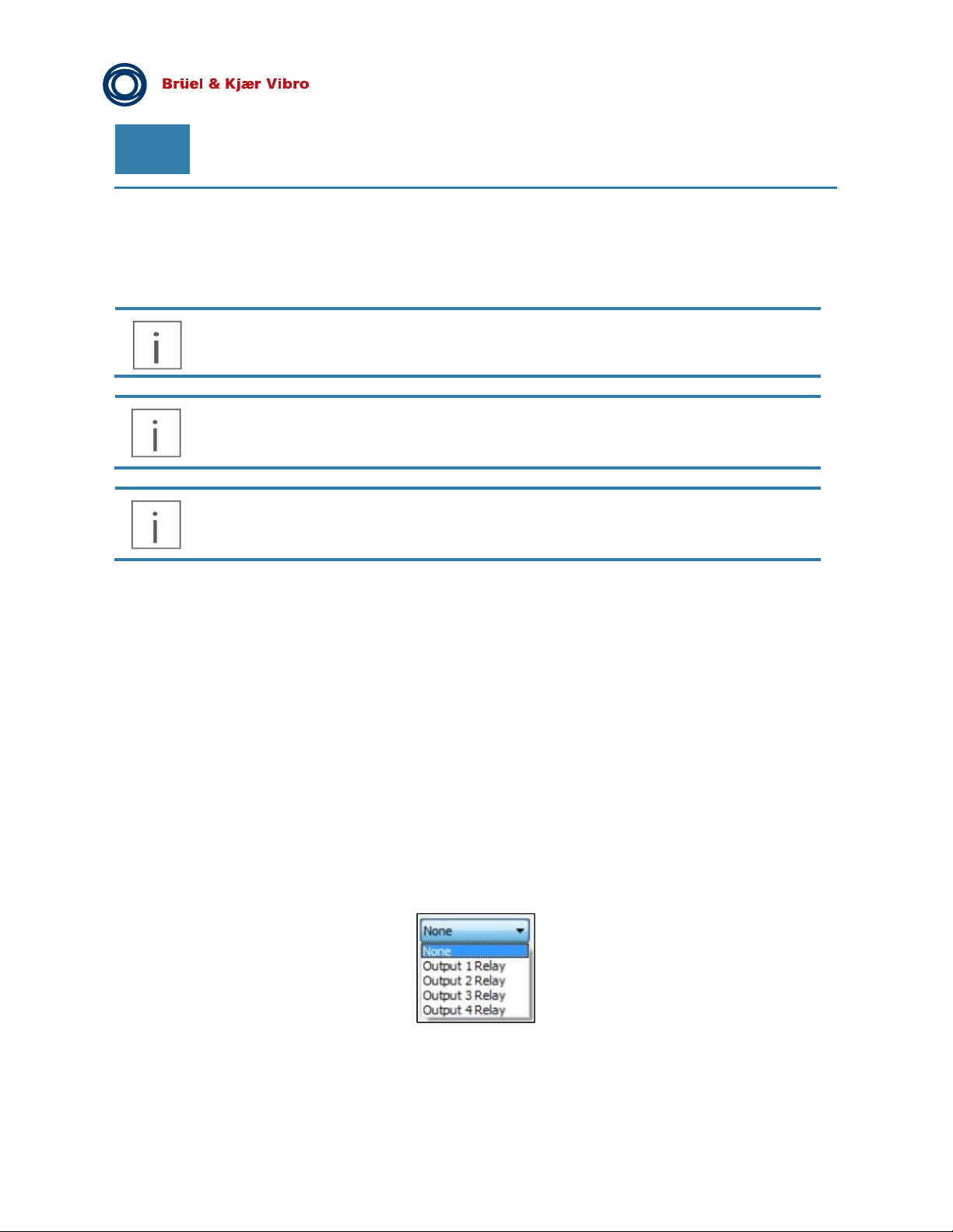
In the example below output type “Relay” is selected, it can be changed to Analog Output.
If output 1 – 4 is defined as analog output, the OK relay can be used as a collection relay for all danger alarms
(Setup Monitor: Safety Monitor (ISO 13849-1).
Please note that all configurable outputs refer to common ground (GND). Outputs selected to
be a current source or voltage will have an output value that can be directly measured
between the respective output terminal and GND.
Please be aware that each of the four (4) outputs can have only one (1) function attached to
it. If e.g. all four outputs are selected to be 4-20 mA current outputs there will be NO relays
available, unless:
© Brüel & Kjaer Vibro ● July 2018 ● C106834.002 / V02 ● █ Page 21 of 84
Technical alterations reserved!
The Protection System feature has been enabled (see section 6.14), which will cause that
ALL Danger Alarms will trigger the Protection System (= System Error relay).
The extension module VC-1801 will provide 12 additional relays.
Page 22
EN
Pre-Release
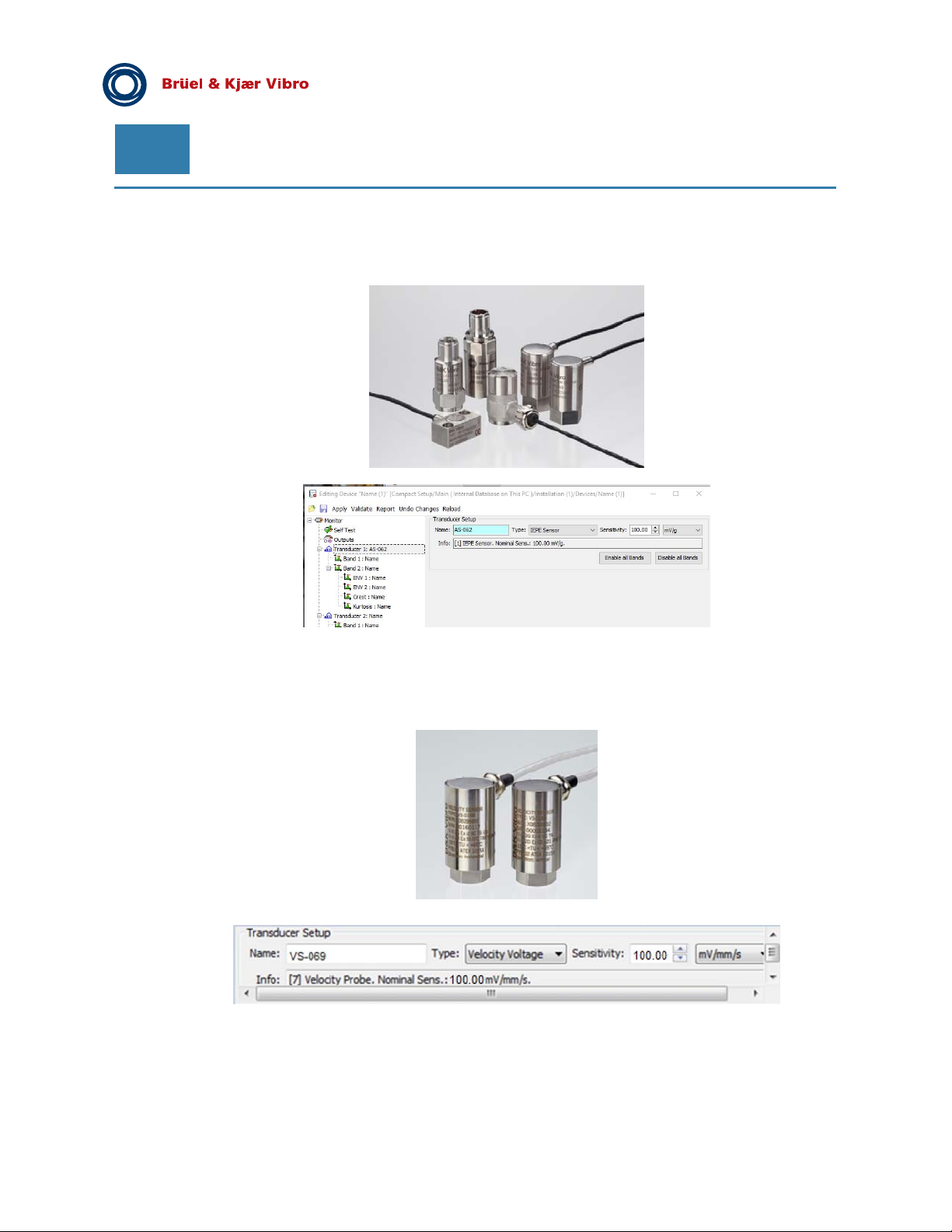
6.5 Sensors
VIBROCONTROL 1850 with CCS accelerometers:
For CCS (IEPE) accelerometer you have to enter its actual sensitivity, which is a value normally provided by
the manufacturer of the sensor. A typical value for standard CCS accelerometers is
100 mV/g.
VIBROCONTROL 1860 with velocity sensors:
For velocity sensor you have to enter its sensitivity, which is a value normally provided by the manufacturer of
the sensor. A typical value for standard velocity sensors is 100 V/mm/s.
Please note: Using velocity sensor of Brüel & Kjær Vibro the frequency linearization for a VS-068/69 is
implemented.
Page 22 of 84
Technical alterations reserved!
█ © Brüel & Kjaer Vibro ● July 2018 ● C106834.002 / V02
Page 23
© Brüel & Kjaer Vibro │Instruction VC-1800 series
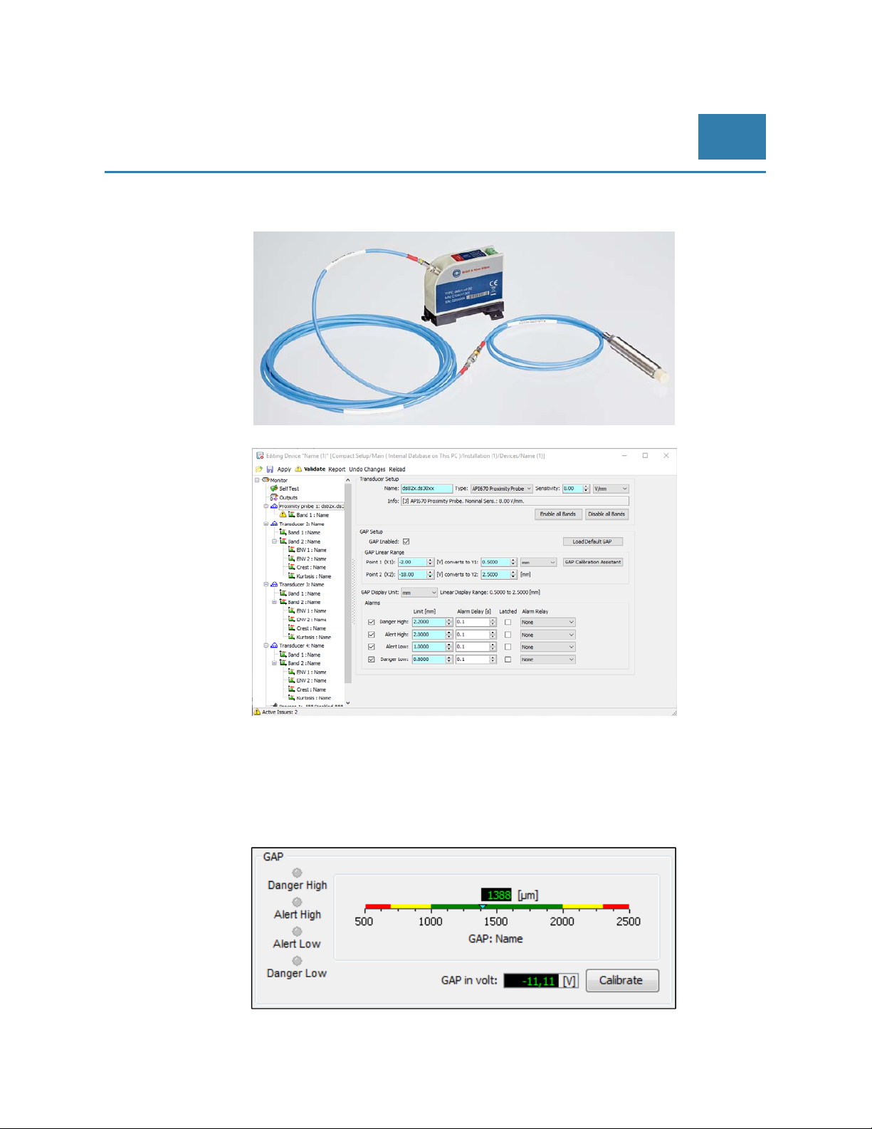
VIBROCONTROL 1870 with displacement sensors:
Setup and Operation of
VIBROCONTROL 18xx
EN
For displacement sensor you have to enter its sensitivity, which is a value normally provided by the
manufacturer of the sensor. A typical value for standard displacement sensor is 8 V/mm.
The setup of the displacement sensor also includes the setup of the GAP analyser (if enabled) that gives an
overall view whether the sensor is operating in its usable range.
The sensitivity of the sensor normally is given in V/mm or mV/µm.
Low-level and High-level GAP alarms are available to indicate that something is wrong with the setup of the
displacement sensor in the application. Each triggered alarm can activate one of the four outputs.
© Brüel & Kjaer Vibro ● July 2018 ● C106834.002 / V02 ● █ Page 23 of 84
Technical alterations reserved!
Page 24
EN
Pre-Release
6.6 VIBROCONTROL 1850: Setup of Band 1 and Band 2
When a band is disabled, the respective vibration parameter will disappear from the main result display of the
Compact Setup Software.
There are the following possibilities with regard to measuring units:
CCS accelerometer : g, m/s2, mm/s, mm or μm
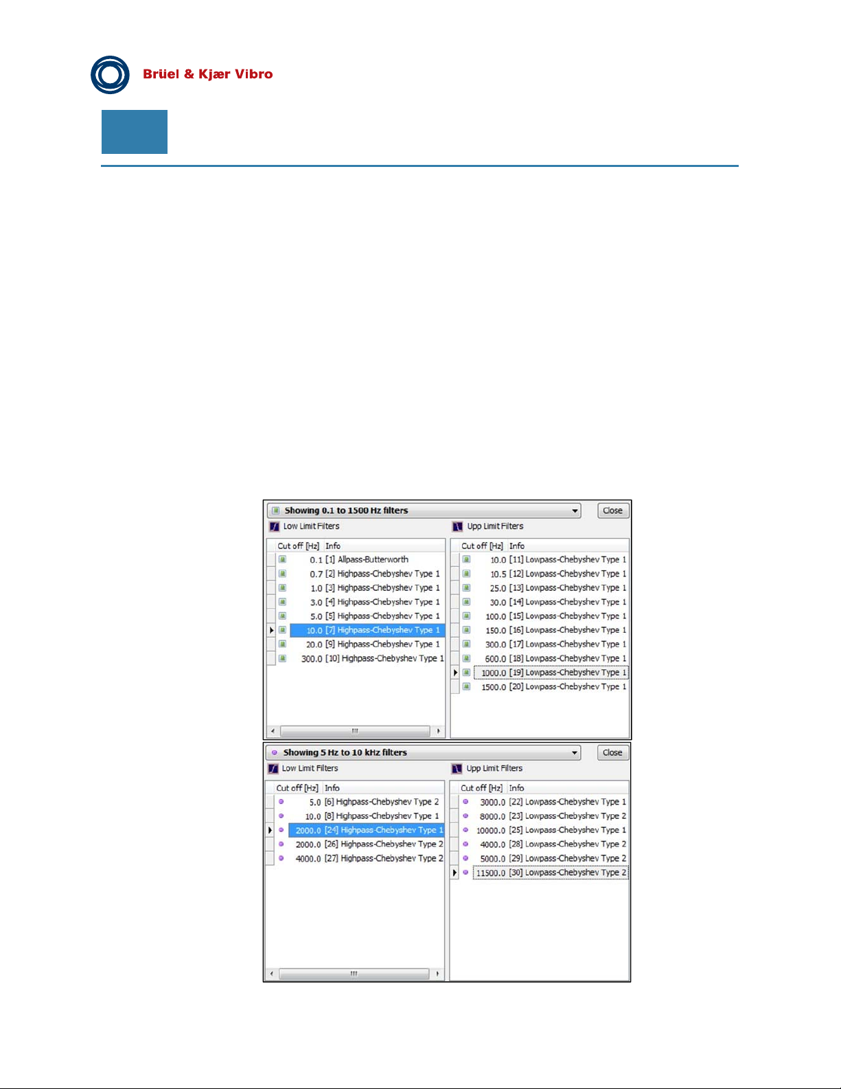
There are two main filter ranges to choose from:
- 0.1 Hz to 1500 Hz:
This filter range is mainly used in Band 1 for classic vibration monitoring with all three sensor types, including
channels with a displacement sensor as sensor. The default value is: 10.0 Hz – 1000.0 Hz.
- 5 Hz to 10 kHz:
This filter range is mainly used in Band 2 for high frequency vibration monitoring of bearings with an CCS
accelerometer. Channels having a velocity sensor or displacement sensor as sensor cannot use these high
frequency band-pass filters. But these sensors can still be used simultaneously in Band 2 at a frequency below
1.500 Hz, but different from the one earlier chosen in Band 1.
The default value is a band-pass filter of 2000.0 Hz to 10000.0 Hz.
Page 24 of 84
Technical alterations reserved!
█ © Brüel & Kjaer Vibro ● July 2018 ● C106834.002 / V02
Page 25

© Brüel & Kjaer Vibro │Instruction VC-1800 series
Depending on the application, the VIBROCONTROL 18xx has three signal detectors to select from:
- True RMS detector:
By default the detector for any Band will be pre-set to “RMS”
The only additional parameter that will have to be set is the RMS Averaging Time (in seconds),
which may have a value between 0.1 and 60.0 seconds.
By default the value of the RMS Averaging Time is pre-set to: 3 seconds.
- Peak detector:
The Peak detector has two additional parameters that will have to be set:
- Attack Time (in milliseconds):
The attack time may have a value between 0.1 and 1000.0 milliseconds
Typical Attack Time 1.0 millisecond
- Decay Time (in seconds):
The Decay Time may have a value between 0.1 and 20.0 seconds
Typical Decay Time 3 seconds
Setup and Operation of
VIBROCONTROL 18xx
EN
6.7 VIBROCONTROL 1850: Setup of the Envelope 1 and Envelope 2
detectors
Bearing failures are one of the most common faults with industrial machines and the envelope detector is
primarily used to detect and diagnose Rolling Element Bearing (REB) faults. When a fault develops, the
vibration becomes amplitude modulated due to periodic changes in the forces. The low frequency vibrations are
filtered away in order only to extract the modulated periodic information from the more sensitive and pure
envelope signal.
The envelope spectrum has shown several major advantages over other methods in very early detection and
fault symptom identification.
The VIBROCONTROL 18xx has two on-board Envelope detectors that may be setup individually. However, the
envelope detectors are part of Band 2 and as such associated to the bandwidth of the band-pass filter selected
in Band 2. Please note that the choice of bandwidth in Band 2 affects the Crest Factor and Kurtosis as well.
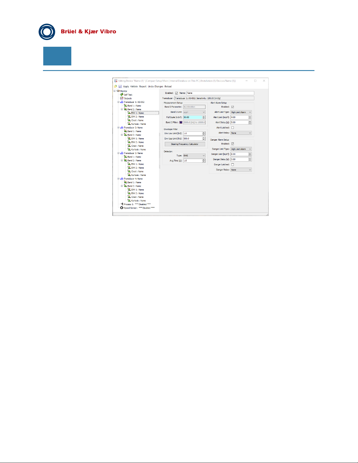
To include an Envelope detector as a part of the general vibration analysis, this function must be enabled by
marking: “Enabled”.
© Brüel & Kjaer Vibro ● July 2018 ● C106834.002 / V02 ● █ Page 25 of 84
Technical alterations reserved!
Page 26
EN
The Envelope is measured in m/s
defined in Band 2, if envelope analysis is to be used.
Pre-Release
2
RMS of the type of unit selected in Band 2. Therefore m/s2 must be pre-
Page 26 of 84
Technical alterations reserved!
█ © Brüel & Kjaer Vibro ● July 2018 ● C106834.002 / V02
Page 27
© Brüel & Kjaer Vibro │Instruction VC-1800 series
The user may set/change the following parameters related to the Envelope detector using the Compact Setup
Software:
- Full scale in m/s2
- RMS Averaging Time in seconds:
This value may vary between 0.1 and 10.0 seconds.
The default value for this parameter is: 3 seconds
- Envelope Low Limit in Hz:
This value may vary between 0.9 Hz and 500.0 Hz.
Use: Bearing Frequency Calculator
The default value for this parameter is: 1 Hz
- Envelope High Limit in Hz:
This value may vary between 4.5 Hz and 500.0 Hz.
Use: Bearing Frequency Calculator
The default value for this parameter is: 500 Hz
Please note that the High Limit must be set at a higher value than the Low Limit.
There are two independent Envelope detectors that each may have a different Envelope Low/High Limit. The
Bearing Frequency Calculator can provide suggestions for Envelope filter settings.
Setup and Operation of
VIBROCONTROL 18xx
EN
6.8 Bearing Frequency calculator
For this purpose, the Compact Setup Software includes a huge database with numerous well- known bearing
manufacturers plus a large number of those bearing models are the most-sold by each manufacturer.
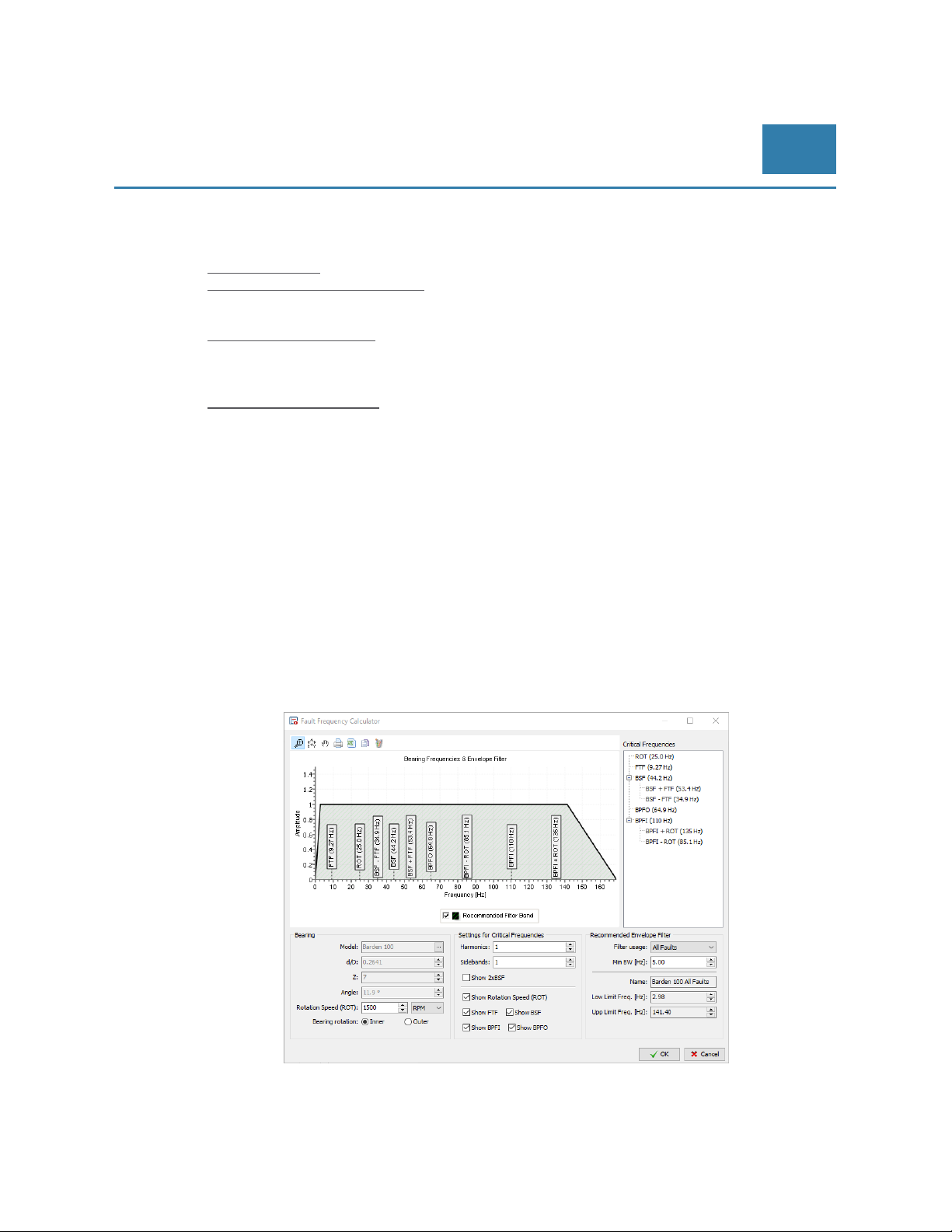
To initiate the Bearing Frequency Calculator please select “Bearing Calculator” in the pop-up menu “Tools” at
the front of the Main Window of Compact Commander Software. This will result in a window similar to that on
the next page to appear:
© Brüel & Kjaer Vibro ● July 2018 ● C106834.002 / V02 ● █ Page 27 of 84
Technical alterations reserved!
Page 28
EN
Once the manufacturer and the bearing model have been selected a number of parameters that are proprietary
for this particular bearing will be calculated and displayed:
Listing of predominant critical frequencies in ball bearings:
- BPFO: Ball Pass Frequency – Outer = Bearing Outer Race Frequency
- BPFI: Ball Pass Frequency – Inner = Bearing Inner Race Frequency
- FTF: Fundamental Train Frequency – Cage Fault
- BSF: Bearing Spin Frequency – Ball Fault
To evaluate the damage frequencies the Bearing Frequency Calculator needs a few additional parameters:
- Rotation speed:
Next enter the rotation speed (ROT) of the bearing (= shaft). The value entered must be in either revolutions
per minute (RPM) or revolutions per second (Hz).
- Settings for Critical Frequencies:
Critical frequencies are the bearing specific vibration frequencies that will be induced on the whole machine as
the result of a fault in the ball bearing.
- Harmonics
Please tell the program how many harmonics must be taken into consideration when calculating the critical
frequencies.
The number of harmonics considered should not exceed the number of balls in the ball bearing. The number of
harmonics can be an integer number between 1 and 10. Default is 1.
- Sidebands
Please tell the program how many sidebands must be taken into consideration when calculating the critical
frequencies.
The number of sidebands can be an integer number between 0 and 10. Default is 1.
When all parameters related to the critical frequencies are selected/entered a listing of the calculated critical
frequencies will become visible in the left top corner of the Bearing Frequency Calculator window.
- Recommended envelope filter:
Pre-Release
- d/D:
d/D is the ratio between the diameter of the balls (d) and the diameter of the circle formed by the
centre-points of the balls in the bearing.
- Z:
Z is the total number of balls or rollers in the bearing.
- Angle:
Angle is the contact angle.
- Bearing Rotation:
Rolling Element Bearings (REB) usually have two circular rings (inner and outer ring), with balls
or other types of rolling elements in between them.
Please determine whether it is the inner ring or the outer ring of the bearing that is rotating.
Indicate the correct movement by marking either “Inner ring rotation” or “Outer ring rotation” in
the Bearing Frequency Calculator setup window.
- Calculating all critical frequencies at once leaves an untidy and difficult to read graph. Study each
predominant critical frequency and its harmonics as well as sidebands on an individual basis, it is
necessary to use a number of narrow band-pass filters. Two of them can be analyzed
simultaneously. By sending the same CCS accelerometer input signal to more than one channel
the same VIBROCONTROL 18xx can produce up to eight different bearing analysis
simultaneously.
Under Filter Usage the critical frequency of interest can be chosen and the relevant filters will be
set automatically calculated by the Compact Setup Software.
Page 28 of 84
Technical alterations reserved!
█ © Brüel & Kjaer Vibro ● July 2018 ● C106834.002 / V02
Page 29
© Brüel & Kjaer Vibro │Instruction VC-1800 series
- - Minimum Bandwidth (in Hz):
Under Minimum Bandwidth the most suitable bandwidth for the narrow band-pass filters
mentioned above will be calculated and be set automatically by the Compact Commander
Software.
- - Name:
Compact Setup Software will automatically select a name for you: “bearing model” + “filter
usage”.
- - Low Limit Frequency (in Hz):
Depending on the parameter settings in the Bearing Frequency Calculator section, the Compact
Commander Setup Software program will automatically set the Lower Frequency of the
recommended band of the envelop filter.
- - High Limit Frequency (in Hz):
Depending on the parameter settings in the Bearing Frequency Calculator section, the Compact
Setup Software program will automatically set the Upper Frequency of the recommended band of
the envelop filter.
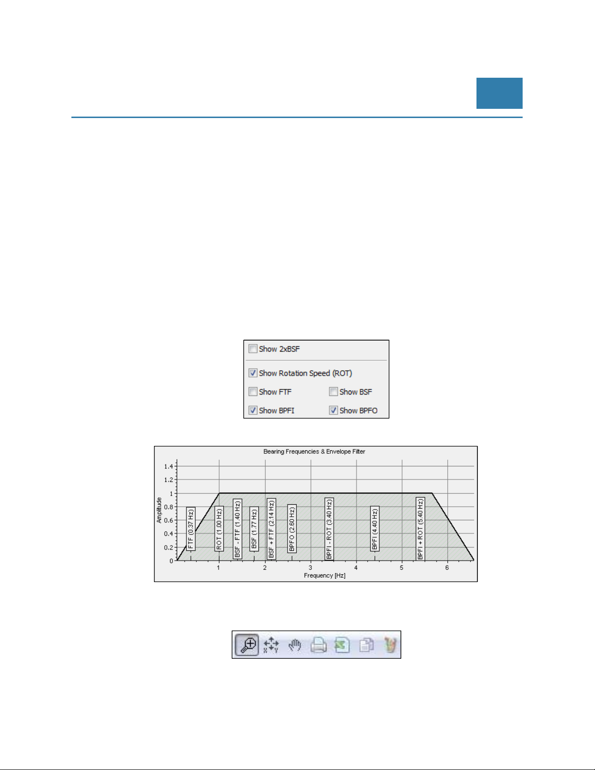
- - Bearing Frequencies & Envelope Filter graph:
The calculated critical frequencies can be displayed in a graph. To have a clear overview it is
once again recommended to display the rotation speed (ROT) and one or only a few critical
frequencies in the graph. Critical frequencies to be displayed in the graph must be marked in the
Bearing Frequency Calculator.
Setup and Operation of
VIBROCONTROL 18xx
EN
Depending on the parameter setup vertical markers indicate critical frequencies where ball bearing problems
are expected.
A number of small icons at the top of the window can be used to manipulate the graph with:
Zoom, Zoom reset, Pan, Print graph, Export to CSV file in Microsoft Excel, Copy to Clipboard and Copy to
Microsoft Paint.
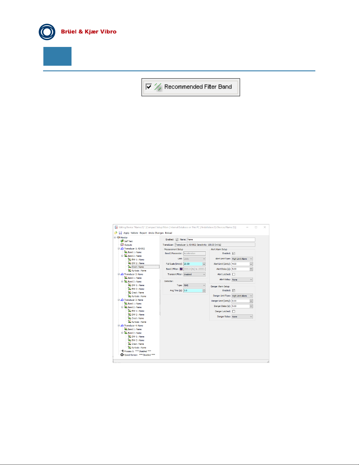
When Recommended Filter Band is marked, a shaded area will become visible in the plot indicating a filter
band recommended by the ball bearing manufacturer covering all selected critical frequencies for the critical
frequencies selected under Filter usage.
© Brüel & Kjaer Vibro ● July 2018 ● C106834.002 / V02 ● █ Page 29 of 84
Technical alterations reserved!
Page 30
EN
When leaving the "Bearing Frequency Calculator", the set parameters are saved with OK.
Pre-Release
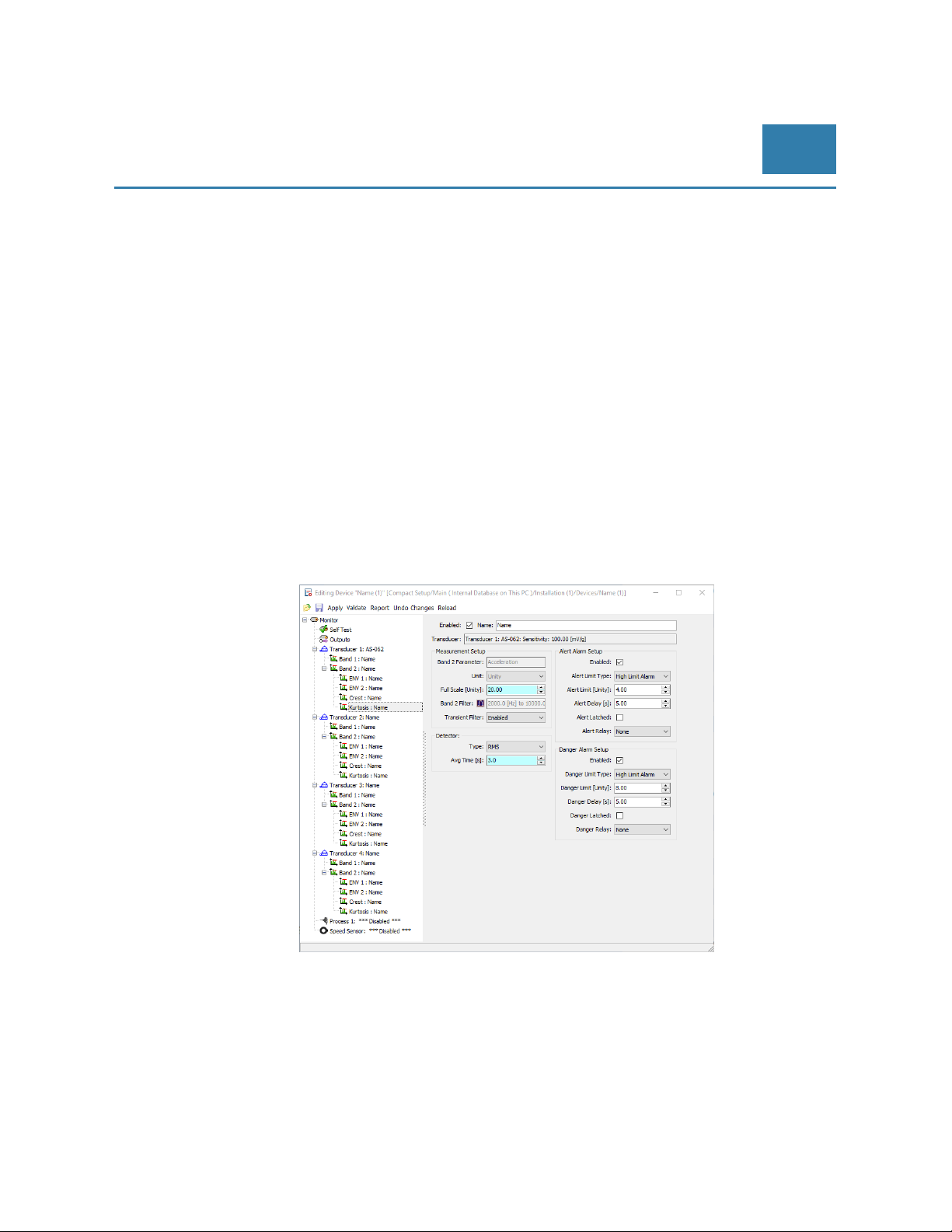
6.9 Crest Factor
The “Crest Factor” is the ratio of the peak value to the RMS value of the vibration signal.
To include the Crest Factor as part of the general vibration analysis, this function must be enabled by marking:
“Enabled”. The Crest Factor of a signal is a unit-less entity.
The calculation of the Crest Factor is carried out within the bandwidth of the band-pass filter selected in Band 2.
Please keep in mind that the Crest Factor function only makes sense for high frequency analysis, i.e. with a
Band 2 band-pass bandwidth starting at 2 kHz.
A transient filter is used to remove unwanted non-periodical noise spikes in the vibration signal that might else
corrupt the measuring result and cause false alarms.
For the Crest Factor the RMS detector is automatically selected and cannot be changed.
The user may set/change the following parameters related to the Crest Factor using the Compact Commander
Software:
- Full scale (unit-less)
This value depends on the application but should never be set below: 10.0 The default value for
this parameter is: 20.00
- RMS averaging time (in seconds). Selectable between 0.1 and 10.0 seconds This value should
never be set below 3 seconds
The default value for this parameter is: 3 seconds
- - Transient filter: enabled or disabled. This function is by default: enabled.
Page 30 of 84
Technical alterations reserved!
█ © Brüel & Kjaer Vibro ● July 2018 ● C106834.002 / V02
Page 31
© Brüel & Kjaer Vibro │Instruction VC-1800 series
Setup and Operation of
VIBROCONTROL 18xx
EN
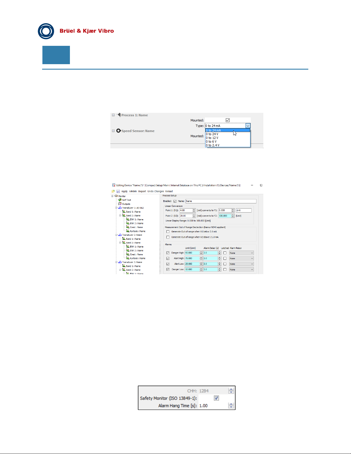
6.10 Kurtosis
The unit-less statistic index “Kurtosis” represents a very good indicator for the analysis in low speed
machineries. To include the Kurtosis as part of the general vibration analysis, this function must be enabled by
marking: “Enabled”. The Kurtosis of a signal is a unit-less entity.
A transient filter is used to remove unwanted non-periodical noise spikes in the vibration signal that might else
corrupt the measuring result and cause false alarms.
The user may set/change the following parameters related to the Kurtosis using the Compact Commander
Software:
- Full scale (unit-less)
This value depends on the application but should never be set below: 10.0 The default value for
this parameter is: 20.00
- RMS averaging time (in seconds). Selectable between 0.1 and 10.0 seconds This value should
never be set below 3 seconds
The default value for this parameter is: 3 seconds
- Transient filter: enabled or disabled. This function is by default: enabled
The calculation of the Kurtosis is carried out within the bandwidth of the band-pass filter selected in Band 2.
Please keep in mind that the Kurtosis function only makes sense for high frequency analysis, i.e. with a Band 2
band-pass bandwidth starting at 2 kHz.
© Brüel & Kjaer Vibro ● July 2018 ● C106834.002 / V02 ● █ Page 31 of 84
Technical alterations reserved!
Page 32
EN
Pre-Release
6.11 Process input (VC-1870 input for axial position)
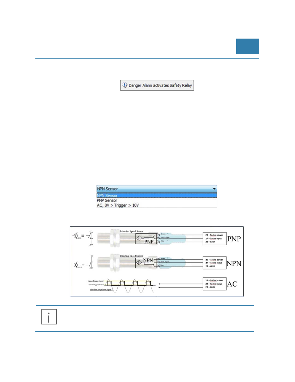
Each VIBROCONTROL 18xx has one embedded Process Input. The input signal is a current or voltage that
represents a linear relationship between voltage/current and a physical parameter like pressure, temperature,
etc... Select Process Input type:
General setup of the Process Input under “Process 1: Name”
The parameter settings of the Process input (Process Setup) is performed under “Edit/Process 1: Name”. The
Process Input must be enabled.
The actual parameter settings of the Process input (Process Setup) is performed
under “Edit/Process 1: Name” and carried out in four (4) stages:
- Linear Conversion
Under Linear Conversion the operator defines the linear (only) relationship between the input voltage/current
and the corresponding value of the physical parameter measured by the connected external Transducer in
either in the units belonging to that sensor, e.g. °C or Pa. A straight line between two points X1Y1 and X2Y2
represents the linear conversion.
- Measurement Out of Range Detection (Namur NE43 appliant)
The sensor is considered to be out of range, if:
- the input at the Process 1 terminal has a value of 10 % below X1
-
the input at the Process 1 terminal has a value of 5 % above X
2
- Alarms
Set four (4) alarms within the values Y1 and Y2:
- Danger High: whenever the Y value exceeds an absolute maximum value that requires action
- Alert High: whenever the Y value exceeds a maximum value that requires attention
- Alert Low: whenever the Y value drops below a minimum value that requires attention
- Danger Low: whenever the Y value drops below an absolute minimum value that requires action
Page 32 of 84
Technical alterations reserved!
█ © Brüel & Kjaer Vibro ● July 2018 ● C106834.002 / V02
Page 33
© Brüel & Kjaer Vibro │Instruction VC-1800 series
Activation of the “Protection System” feature:
Selecting this feature will cause any Danger Low or Danger High alarm to activate the highly reliable System
Failure relay
Setup and Operation of
VIBROCONTROL 18xx
EN
6.12 Speed Sensor (Tacho) input
General setup of the Tacho Input under “Speed Sensor: Name”
The parameter settings of the Tacho Input (Speed Sensor Setup) is performed under “Edit/Speed Sensor:
Name”.
To start with the Tacho Input must be enabled by marking the small square field next to “Enabled:”
The actual parameter settings of the Tacho Input (Speed Sensor Setup) is performed under “Edit/Speed
Sensor: Name” and carried out in four (4) stages:
- Properties:
Under “Properties” the operator first defines the type of speed sensor that will be connected to
the Tacho terminal of the VIBROCONTROL 18xx.
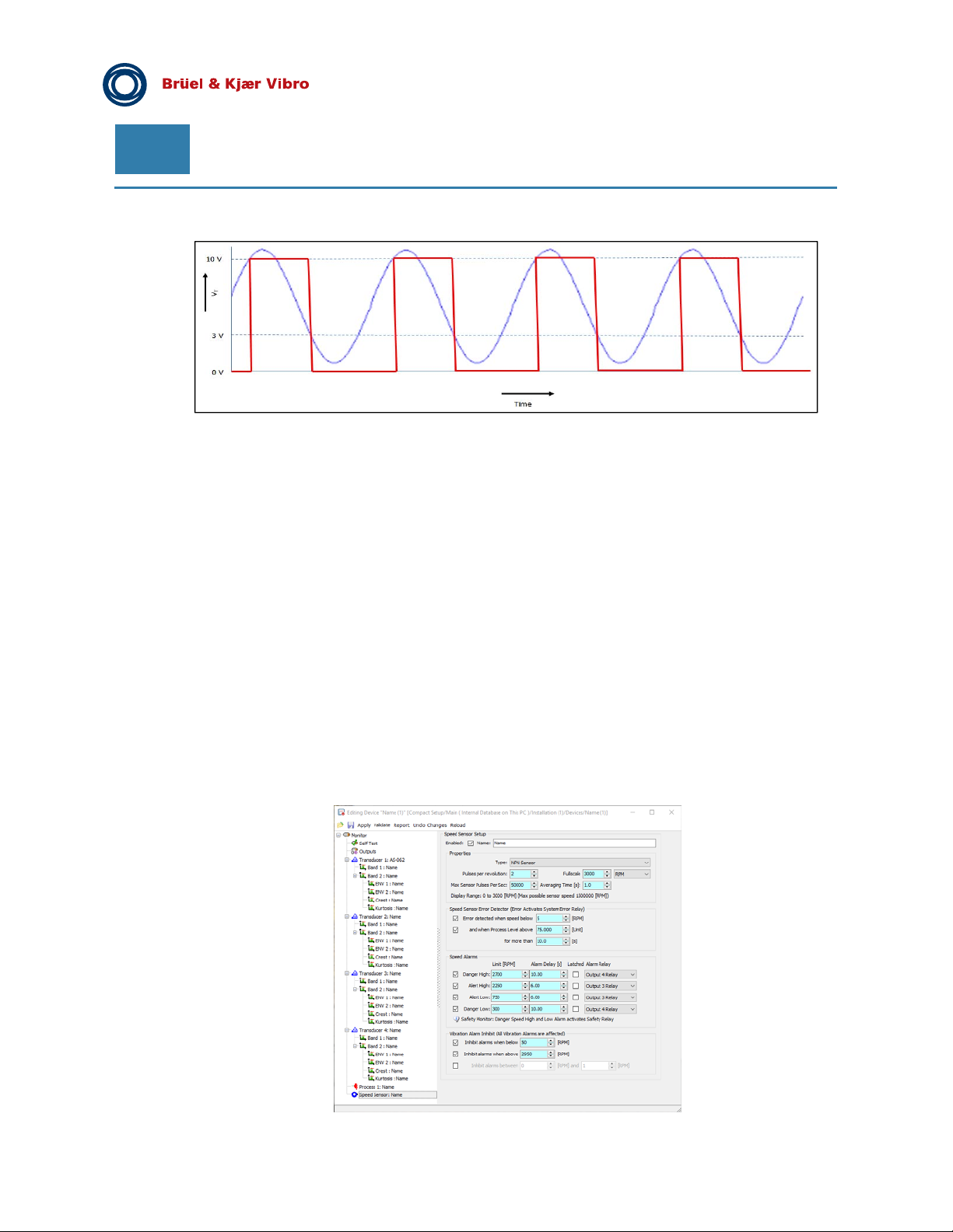
Please refer to the drawing below to see how the VIBROCONTROL 18xx speed sensor input is connected to
the different types of sensors.
The signal presented by the speed sensor (tachometer) to the VIBROCONTROL 18xx
terminal #24 should comply to:
- Low level: 0 - 3 VoltPP
- High level: 10 - 24 VoltPP
© Brüel & Kjaer Vibro ● July 2018 ● C106834.002 / V02 ●
Technical alterations reserved!
█
Page 33 of 84
Page 34
EN
The drawing below explains the function of the AC-triggered type of speed sensor:
Pre-Release
The next step is to define the unit of rotation to be used:
○ ~ number of rotations per second (RPS)
○ ~ number of rotations per minute (RPM).
The number of “Pulses per revolution (PPR)” is the number of pulses presented to the Tacho
Input per one (1) revolution of the application.
The value for the full scale in the display is chosen in the field “Fullscale” (FS). FS should have a
value of at least 1 RPS/RPM and the value of PPRxFS may never exceed 50000 for RPS or
3000000 for RPM.
Alarm Inhibit (All vibration Alarms are effected)
In order to suppress alarms in certain speed ranges, speed intervals, speed overruns or speed underruns can
be defined for which no alarm is to be triggered.
Speed Sensor Error Detector (Error Activates System Error Relay), when:
1) the sensor speed reaches a low value below a certain RPS/RPM.
2) the value of another parameter, e.g. temperature or gas pressure, connected to the “Process
1: Name” terminal exceeds a certain pre-set high level
3) the dangerous situation described under 1) and 2) lasts for at least a certain pre-set number of
seconds
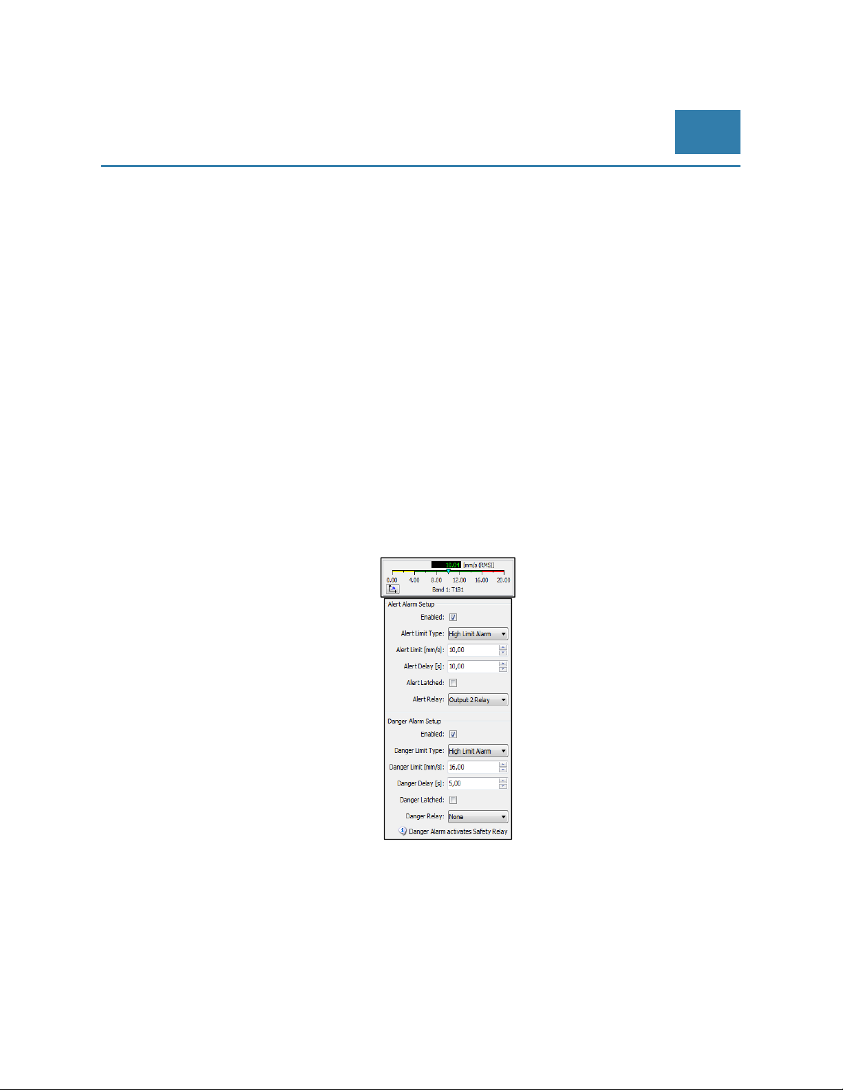
Example of a typical speed sensor parameter setup:
Page 34 of 84
Technical alterations reserved!
█ © Brüel & Kjaer Vibro ● July 2018 ● C106834.002 / V02
Page 35
© Brüel & Kjaer Vibro │Instruction VC-1800 series
Setup and Operation of
VIBROCONTROL 18xx
EN
6.12.1 Speed sensor selection
It is recommended to use either a NPN or PNP type, i.e. a standard interface that all Speed sensor suppliers
meet with a variety of different probes.
Only 3-wires are needed: sensor DC supply, Signal and ground.
Some suppliers refer to NPN and PNP type Speed sensors as “3 Wire DC”.
6.13 Alert and Danger alarms
The final task associated with setting the parameters of each function, such as vibration, process and RPM
measurement, is to set the alarm values. There are two alarms attached to each vibration measuring function: an
Alert alarm and a Danger alarm.
Only enabled alarms will have a function in the safety task of the VIBROCONTROL 18xx device.
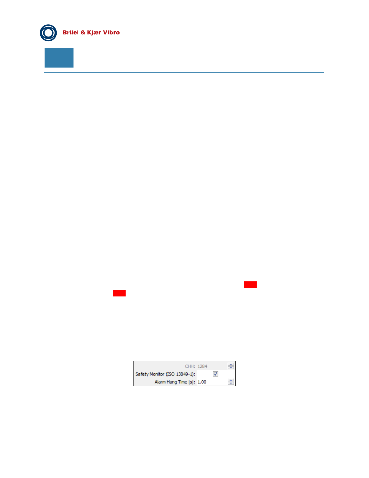
The parameter setup of the Alert alarm and the Danger alarm are very similar and consists of setting the
following parameters:
Alert Limit Type
High Limit Alarm or Low Limit Alarm is the possible choice here. For normal operation (= default)
the High Limit Alarm function is selected. The alarm will get triggered as soon as the value of the
vibration parameter exceeds the pre-set trigger level for that particular alarm for a period longer
than the Danger delay time.
However, if the end-user would like to have an alarm that instead triggers on a value below the pre-set trigger
level for that particular alarm, the Low Limit Alarm function should be selected.
© Brüel & Kjaer Vibro ● July 2018 ● C106834.002 / V02 ● █ Page 35 of 84
Technical alterations reserved!
Page 36
EN
Pre-Release
Alert Delay and Danger Delay time:
The delay time is the minimum continuous time that must have passed before the alarm in
question is activated.
Alert Latched and Danger Latched:
A latched alarm will not be deactivated once the conditions for triggering a particular alarm in
place. The alarm latch function can be initiated by marking the Alert Latched and/or Danger
Latched.
Alert Relay and Danger Relay:
When an alarm is triggered, it can be signalled by one of the 4 outputs through one of the relays.
For increased functional safety the Danger alarm can also be associated with the highly reliable
System Failure redundant mechanical relays. See section 6.14 of this manual. By default the
alarm relays will be pre-set to “None”.
6.14 System Failure (OK)
The VIBROCONTROL 18xx has an internal surveillance system, including a watchdog. This surveillance
system will constantly monitor the correct functioning of the unit. As soon as an internal fault is detected, such
as a sensor bias error, a processor error, or a not-passed self-test, this is considered to be a very serious
situation and a system failure procedure will be activated.
The system failure safety relay has a “break” function so that a power failure will also be detected and
considered to be a system failure as well.
Whenever a system failure is detected the following actions are taking place:
System failure safety relay will be activated (break)
The analog output drops to 0 mA
The „OK“ LED at the front panel of the enclosure will either flash Red for critical errors or light
continuously Red for non-critical errors.
The action of the System Failure relay outputs at terminal #3 and terminal #4 are both insulated from ground
(GND) and therefore galvanic insulated from the rest of the VIBROCONTROL 18xx device.
The System Failure output of the VIBROCONTROL 18xx consists of two mechanical relays that are coupled in
series. This redundancy considerably increases the reliability of the System Failure safety relay.
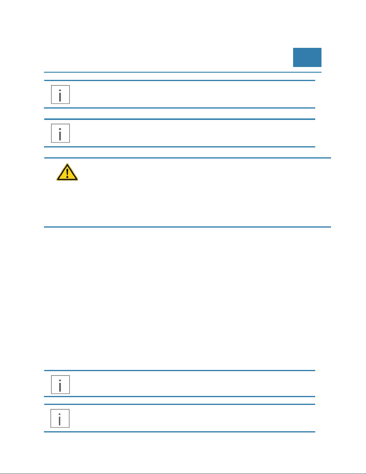
During the configuration procedure of the VIBROCONTROL 18xx it is possible under Edit/Monitor to mark the
feature “Protection System (ISO 13849-1)” and set its alarm hang time.
Selecting this feature will cause any danger alarm to activate the highly reliable System Failure relay.
“Borrowing” the system failure safety relay for Danger alarms drastically increases the reliability of any Danger
alarm function and thus the level of functional safety of the machine of which the VIBROCONTROL 18xx
monitors the vibration.
Page 36 of 84
Technical alterations reserved!
█ © Brüel & Kjaer Vibro ● July 2018 ● C106834.002 / V02
Page 37
© Brüel & Kjaer Vibro │Instruction VC-1800 series
An enabled Protection System Feature will be indicated by “Danger Alarm activates OK
Relay.
In case of a persistent system failure, please return your device to the manufacturer for repair.
The system failure relays are mechanical relays. Excessive current and/or voltage will damage
the relay. For this reason, please do not apply any power source directly to the relay. Protect
the relay with a resistor in series that will limit the current.
The following conditions for the OK relay output should not be exceeded in your application:
- Insulation 100 V
- Maximum current load 100 mA
- Max load voltage ±28 V Further specifications:
- ON resistance < 12.9 Ω
- Off state leakage current max. 10 μA
Setup and Operation of
VIBROCONTROL 18xx
EN
6.15 Alarm Hang Time
The “Alarm Hang Time” is the time an alert or danger alarm remains activated even though the vibration level
has decreased to below the trigger level.
The system failure relay has no hang time, but will remain activated until the system failure condition has
ended.
6.16 Overload, Cable Short and Cable Break
The VIBROCONTROL 18xx watchdog surveys each pair of input terminals where the sensors are connected to
the device:
Terminals #13 and #14 for sensor 1
Terminals #15 and #16 for sensor 2
Terminals #17 and #18 for sensor 3
Terminals #19 and #20 for sensor 4
The detection of an overload condition generates a system failure (NOK status).
The OK relay is active. The OK LED shows NOK.
The DC analog output will move to 0 mA to indicate the overload condition as a failure.
© Brüel & Kjaer Vibro ● July 2018 ● C106834.002 / V02 ●
Technical alterations reserved!
█
Page 37 of 84
Page 38
EN
Pre-Release
6.17 Over range
The VIBROCONTROL 18xx Vibration Monitor is provided with an over range detection system that detects the
occurrence of an over range situation, i.e., when the vibration level exceeds the maximum vibration level of the
measuring range.
The detection of an over range will not generate a system failure.
The DC analog output will move to 20,5 mA to indicate the over range condition.
The status of the alarm relays will not change.
6.18 Output configuration
The VIBROCONTROL 18xx has four independent outputs at terminals #9, #10, #11 and #12 that can be
configured to have either the function of a relay, or become a DC analog output, which is direct proportional to
the vibration level of the function the Analog DC output is assigned to. The selection of the four outputs is
described in section 6.4.
6.18.1 Relays
The VIBROCONTROL 18xx Vibration Monitor has four solid state alarm relays that can be attached to any of
the alert and danger alarms. Relays must be enabled in order to become activated, if triggered.
One alarm relay can serve more than one alarm thus making it not always possible to immediate determine
exactly which vibration measuring function caused an alarm relay to become activated.
The “contacts” of all alarm relays are closed (= make) while in standby and open (= break) when activated.
Therefore the alarm relay(s) also appear to be activated whenever the main power of the VIBROCONTROL
18xx fails.
The four VIBROCONTROL 18xx solid-state alarm relays are named respectively: “Output 1 Relay” (terminal
#12), “Output 2 Relay” (terminal #11), “Output 3 Relay” (terminal #10) and “Output 4 Relay” (terminal #9).
Relays will only be available at a particular output (terminal), if a relay was selected during the configuration of
that output. For a detailed description about how to configure the outputs of the VIBROCONTROL 18xx, please
read section 6.4 of this manual.
Page 38 of 84
Technical alterations reserved!
█ © Brüel & Kjaer Vibro ● July 2018 ● C106834.002 / V02
Page 39
© Brüel & Kjaer Vibro │Instruction VC-1800 series
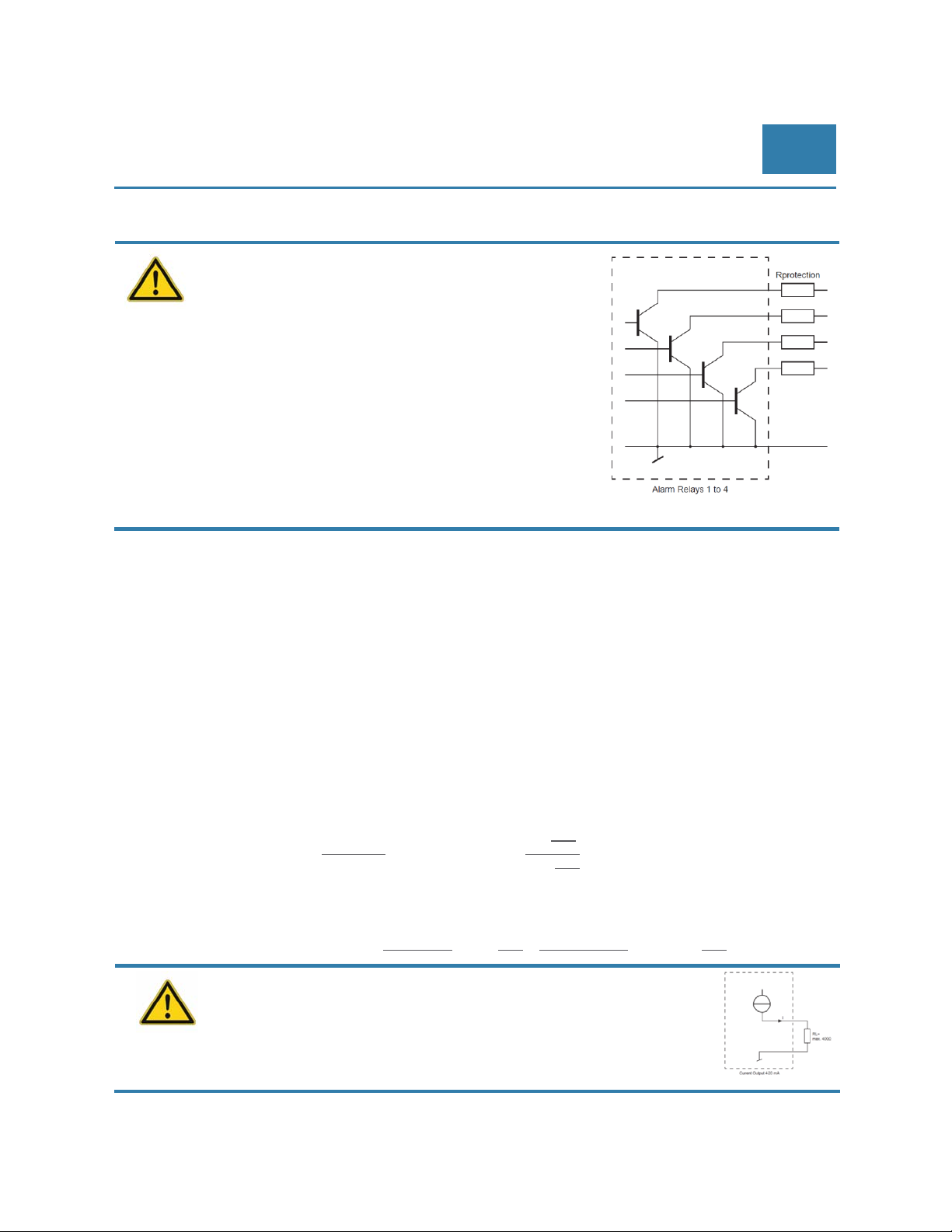
The alarm relays are non-insulated MOSFET relays
that only will work with positive voltages. Excessive
current and/or voltage will damage the relay. For this
reason please do not apply any power source
directly to the relay. Protect the relay with a resistor
in series that will limit the current.
The following conditions for the relays should not be
exceeded in your application:
- Type: Open drain
Insulation 30 V
- Maximum current load 100 mA
- Max load voltage +28 V
Further specifications:
- ON resistance < 12.9 Ω
- Off state leakage current max. 10 μA
6.18.2 Analog outputs
Setup and Operation of
VIBROCONTROL 18xx
EN
There are four different analog dc output configurations that can be selected:
0 – 20 mA
4 – 20 mA, which is the default configuration of an Analog DC output
0 – 10 V
2 – 10 V
For example:
An output current of 4 mA at the dc output represents a minimum value of 0, e.g. 0 mm/s, while
20 mA at the output represents full scale, e.g. 100 mm/s.
Any value between 0 mm/s and 100 mm/s will then be positioned directly linear between 4 mA and
20 mA at the analog output.
Example 1: the vibration level is a known 60 mm/s. The analog output should show:
4
out
Example 2: the analog output shows 15 mA. The velocity is:
The load impedance on the analog dc current output
should not exceed 400 Ω.
∗164
4
out
16
100
60
100
15 4
∗
∗1613.6
16
68,75
mm
s
© Brüel & Kjaer Vibro ● July 2018 ● C106834.002 / V02 ●
Technical alterations reserved!
█
Page 39 of 84
Page 40
EN
Pre-Release
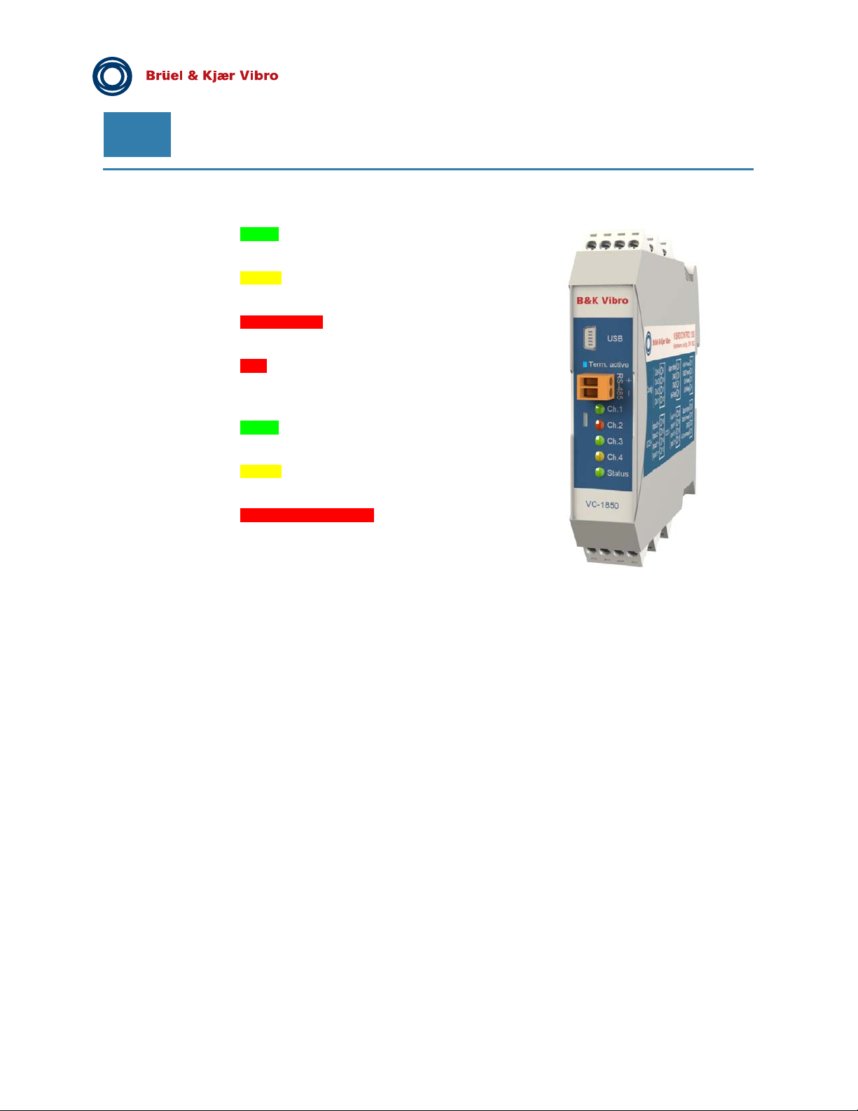
6.19 Light Emitting Diodes (LEDs)
Status Green:
Normal operation. No events.
Yellow-flashing:
Selftest
Red - flashing:
System Failure
Red:
Cable short / Break , together with
flashing Red Channel LED
Ch. 1/2/3/4 Green:
Normal operation. No events.
Yellow:
Alert alarm
Red-flashing (50/100%):
Danger alarm
Cable Short, together with Red
Status LED
Cable Break, together with Red
Status LED
Term.
active
A Blue LED marked “Term. active” at the front panel of the VIBROCONTROL 18xx enclosure
indicates whether a 120 Ω termination resistor is in place between the contacts of the yellow
RS-485 connector. This is required in case the VIBROCONTROL 18xx in question is the last
device in a chain of devices on a RS-485 bus. The termination resistor is (de-)activated by
sliding (left/right) a very small button that can be found behind a small hole at the front of the
enclosure.
Page 40 of 84
Technical alterations reserved!
█ © Brüel & Kjaer Vibro ● July 2018 ● C106834.002 / V02
Page 41

© Brüel & Kjaer Vibro │Instruction VC-1800 series
Setup and Operation of
VIBROCONTROL 18xx
EN
6.20 Reset of Alarms
An active non-latched Alert or Danger alarm will automatically be cleared when the vibration level is reduced
below its trigger level for a period longer than the hang time of typical 1 second.
An active non-latched Alert or Danger alarm will automatically be cleared when the vibration
level is reduced below its trigger level for a period longer than the hang time of typical 1
second. Alarms that are latched can be reset by connecting the “Alarm Inhibit” (at terminal #5)
to ground (GND) for a short while. This procedure will reset all Alert and Danger alarms at
once.
When an alarm is cleared the corresponding channel LED at the front panel of the
VIBROCONTROL 18xx will turn Green.
6.21 Inhibit Alarms
Alarms can be inhibited (disabled) under certain process conditions (for example, for certain speed ranges).
Inhibit is activated by connecting terminal #5 on the enclosure (marked: “Alarm Inhibit”) to ground (GND), e.g.
terminal #6. This procedure will inhibit all Alert and Danger alarms at once, but NOT a System Failure alarm.
Please note that inhibit overrules the latch function. Any latched alarms (except the system
failure alarm) will be reset after “Alarm Inhibit” has ended.
Inhibit should be used with care. Leaving the vibration monitor with “Inhibit” ON would disable
all Alert and Danger alarms.
© Brüel & Kjaer Vibro ● July 2018 ● C106834.002 / V02 ●
Technical alterations reserved!
█
Page 41 of 84
Page 42
EN
Pre-Release
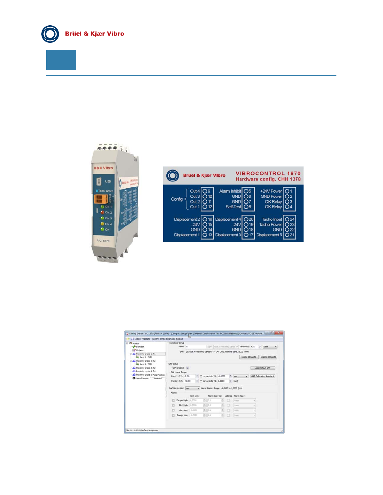
7 VIBROCONTROL 1870 - Displacement measurement
Relative shaft vibration 4 channels (Input Terminals 13 – 20)
Axial shaft position 1 channel (Input Terminals 21 – 23)
Speed 1 channel (Input 23 – 24)
7.1 VIBROCONTROL 1870 – 4-channel - relative shaft vibration
Specific setup of VIBROCONTROL 1870 relative shaft vibration
The setting of the measuring parameters of the VIBROCONTROL 1870 can be carried out with Compact Setup
Software:
Page 42 of 84
Technical alterations reserved!
█ © Brüel & Kjaer Vibro ● July 2018 ● C106834.002 / V02
Page 43
© Brüel & Kjaer Vibro │Instruction VC-1800 series
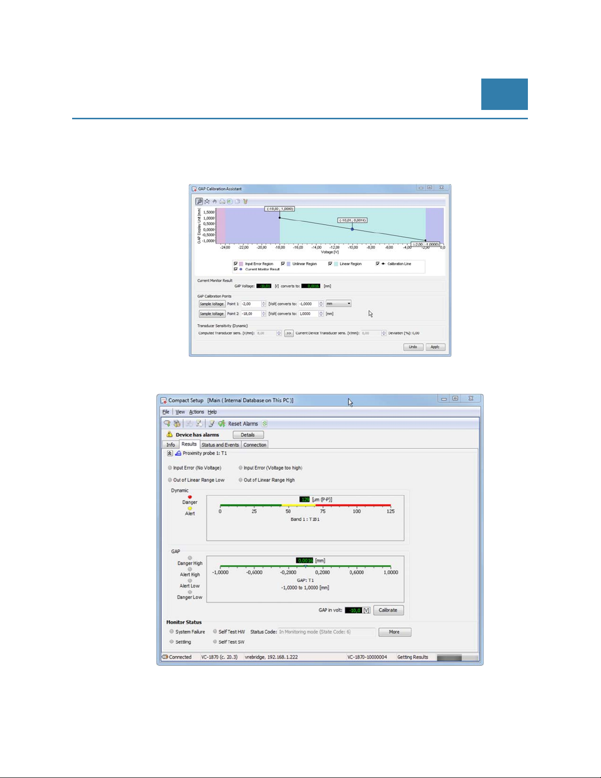
Four displacement sensors can be connected to monitor relative shaft vibration. For setup the gap voltage
needs to be adjusted with in a range from -2 to -18 V DC. Ideally the sensor positioning should be close to -10
V DC to allow maximum of relative shaft vibration in both direction.
The GAP Calibration Assistant is supporting the setup with a graphical display:
The measurement results for the relative shaft vibration and corresponding GAP value are displayed via results
button:
Vibrocontrol 1870 - Displacement
measurement
EN
© Brüel & Kjaer Vibro ● July 2018 ● C106834.002 / V02 ●
Technical alterations reserved!
█
Page 43 of 84
Page 44
EN
Pre-Release
Overload and Over range detection
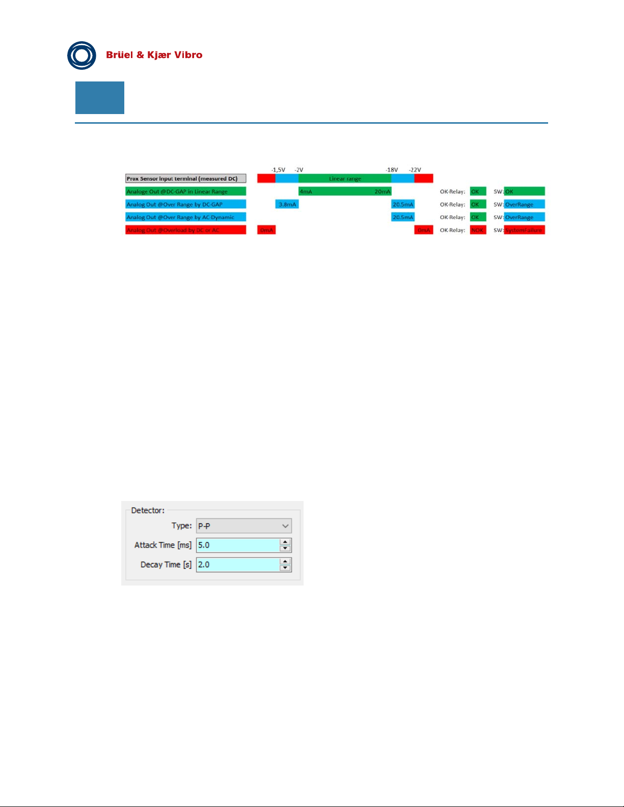
The graphic below is describing the instrument behavior during over range and overload situations.
Over range detection
When AC Dynamic (relative shaft vibration) is in Over Range:
the corresponding analog output is set 20.5 mA.
When DC-GAP (sensor GAP position) is in Over Range:
analog output will saturate at either 3.8mA (lower) or
analog output will saturate at 20.5mA (upper)
-see the blue colour in graphics above.
Overload Detection
When AC (relative shaft vibration) or DC (sensor GAP position) Overload is detected:
the analog output is set to 0 mA
the system error relay is activated (red LED)
Special Hint for Peak to Peak measurements:
The default setup for Peak to Peak Measurements shows Attack Time of 5.0 ms and the Decay time shows of
2,0 s.
Shorter attack and decay times may lead to a reduced accuracy of the measurements. This is also valid for
peak measurements.
Page 44 of 84
Technical alterations reserved!
█ © Brüel & Kjaer Vibro ● July 2018 ● C106834.002 / V02
Page 45
© Brüel & Kjaer Vibro │Instruction VC-1800 series
Vibrocontrol 1870 - Displacement
measurement
EN
7.2 VIBROCONTROL 1870 – Axial shaft position
Specific setup of VIBROCONTROL 1870
- One Channel - Axial shaft position (via Terminal 21 & 22)
PLEASE NOTE:
For VIBROCONTROL 1850 & 1860 terminal 21 & 22 are labelled and used for process input.
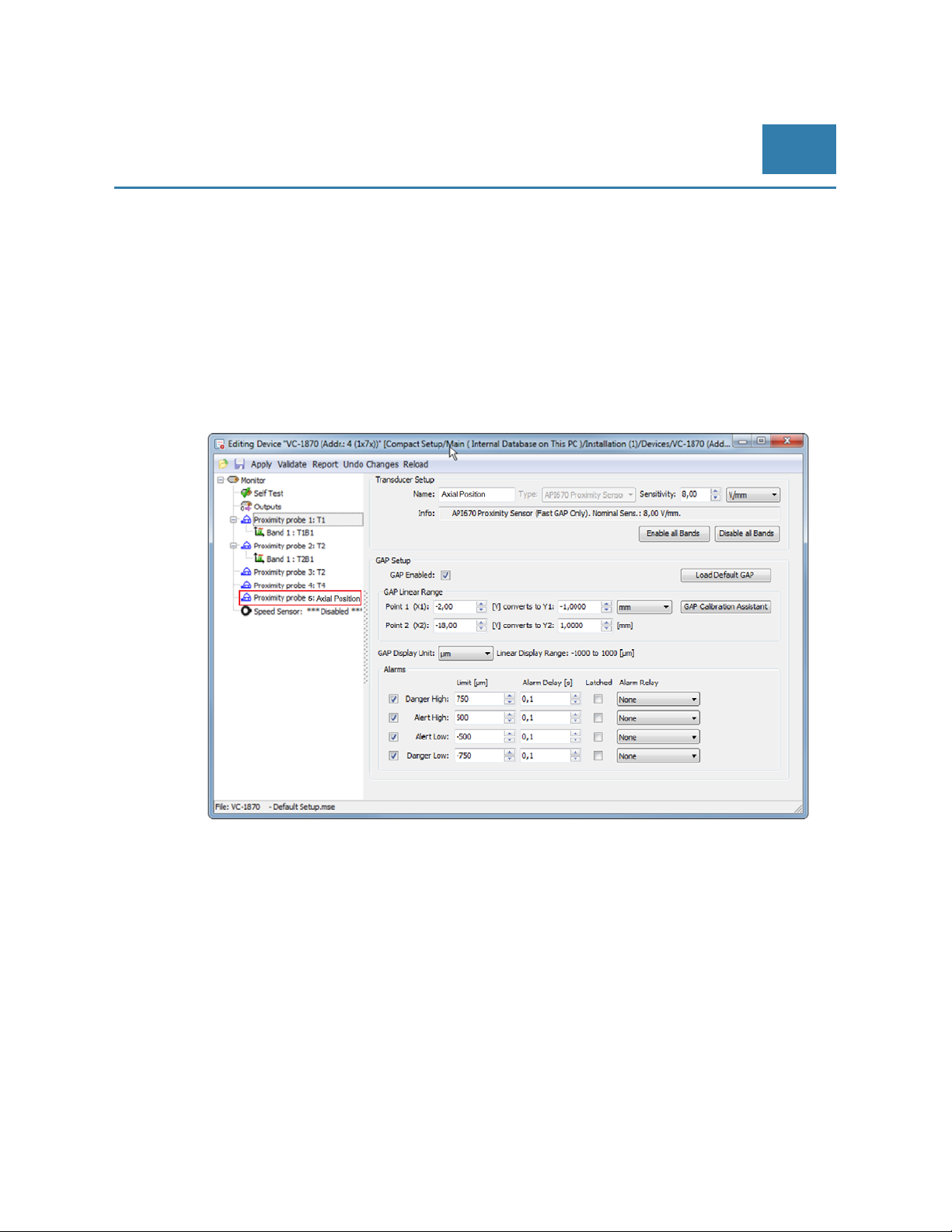
The setting of the measuring parameters of the VIBROCONTROL 1870 for axial shaft position measurement
can be carried out with Compact Setup Software:
One displacement sensor can be connected to monitor axial shaft position (Terminal 21 to 23).
For setup the gap voltage needs to be adjusted with in a range from -2 to -18 V DC.
For monitoring axial position in both direction (towards and away from the sensor)
ideally the sensor positioning should be close to -10 V DC to allow maximum of relative shaft
vibration in both direction (in this case + 1mm and – 1 mm).
For monitoring axial position only in one direction the GAP position for the sensor should be
closed to either -2 V DC or -18 V DC.
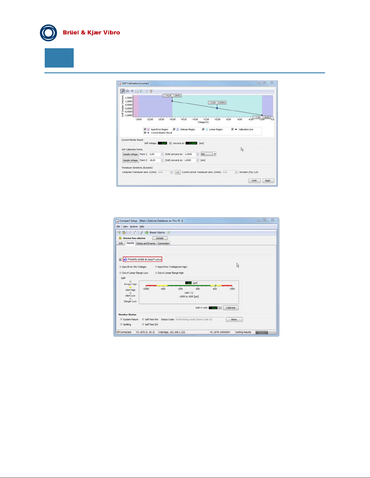
The GAP Calibration Assistant is supporting the setup with a graphical display:
© Brüel & Kjaer Vibro ● July 2018 ● C106834.002 / V02 ● █ Page 45 of 84
Technical alterations reserved!
Page 46
EN
The measurement results for the axial shaft position and corresponding GAP value are displayed via results
button:
Pre-Release
Overload and Over range detection
See VIBROCONTROL 1870 above.
Page 46 of 84
Technical alterations reserved!
█
© Brüel & Kjaer Vibro ● July 2018 ● C106834.002 / V02
Page 47
© Brüel & Kjaer Vibro │Instruction VC-1800 series
Extension Modules for
VIBROCONTROL 1850/1860/1870
EN
8 Extension Modules for VIBROCONTROL 1850/1860/1870
8.1 VIBROCONTROL 1801 Relay Module- 12 relays
8.1.1 General
With four alarm relays inside each VIBROCONTROL 18xx it will be necessary to associate more than one
alarm to at least one relay (i.e. “overlapping” alarms) if relay outputs are chosen for five or more different
alarms.
If one or more outputs of a VIBROCONTROL 18xx are configured not to be a relay but e.g. an analog output
such output cannot be configured to have a relay function simultaneously. This means that if each of the four
available VIBROCONTROL 18xx outputs is associated with a sensor analog input signal there will not be any
relay(s) available for alert or danger alarms of any vibration parameter monitored. By attaching a
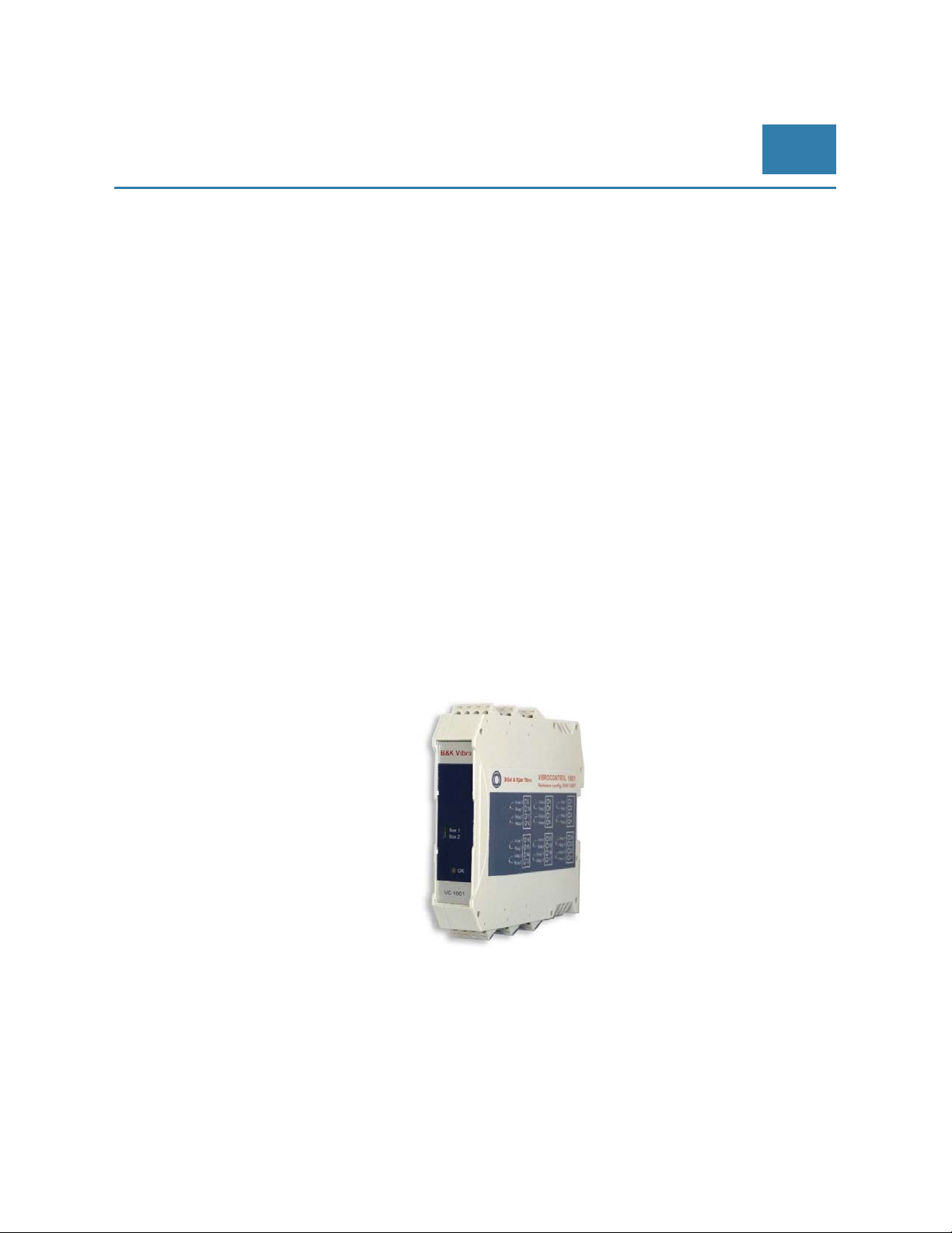
VIBROCONTROL 1801 Relay Module to a VIBROCONTROL 18xx there will be always twelve alarm relays
available.
8.1.2 VIBROCONTROL-1801 Relay Module
VC-1801 Relay Modules to one VIBROCONTROL 18xx. This will increase the number of relays with 12
additional.
Relay box select switch:
The front panel of the VC-1801 Relay Module has a small switch that has two positions:
Relay-Module: Default switch position (1) when a VC-1801 is connected to a
VIBROCONTROL 18xx (switch position (2) dedicated for future expansion).
8.1.3 Make/Break of relays
All solid-state relays of a VC-1801 Relay Module are by default configured to go from the “make” to the “brake”
status when the associated alarm in a VIBROCONTROL 18xx is activated. This has the advantage that the
relay(s) will act as being activated in case of a power failure.
© Brüel & Kjaer Vibro ● July 2018 ● C106834.002 / V02 ● █ Page 47 of 84
Technical alterations reserved!
Page 48
EN
Pre-Release
8.1.4 Mounting
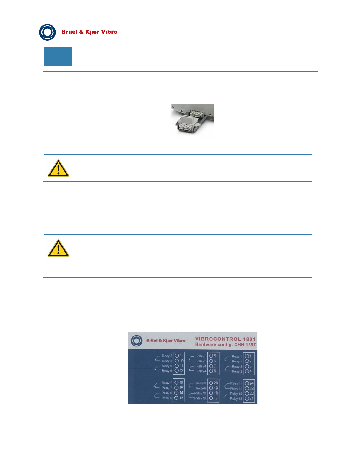
The VIBROCONTROL 18xx and the VC-1801 relay Module(s) must be positioned next to each other with both
5- pin DIN-rail bus connectors in place.
It does NOT matter at which side of the VIBROCONTROL 18xx the VC-1801 Relay Module is positioned.
There may NOT be more than one (1) VIBROCONTROL 18xx on the same DIN-rail bus
connection.
8.1.5 External connections
Power:
The VC-1801 Relay Module gets its main power from an adjacent VIBROCONTROL 18xx via the
5-pin DIN-rail bus connector at the bottom of the DIN-rail enclosures.
Before connecting the VIBROCONTROL 18xx and VC-1801 together by joining the DIN-rail
connector at the bottom of both devices we strongly recommend:
PLEASE, FIRST DISCONNECT THE VIBROCONTROL 18xx FROM THE MAIN POWER.
Although there have been taken sufficient measures to allow a hot-swap of the
VIBROCONTROL 18xx and VC-1801 devices there is still a remote chance that one of the
devices will get damaged in the process.
Data:
The dataflow between the VIBROCONTROL 18xx and the VC-1801 Relay Module takes (also) place via the 5pin DIN-rail bus connector at the bottom of the DIN-rail enclosures.
Relays:
The “contacts” of the twelve relays are pairwise present at the screw terminals at the side of the
VC-1801 enclosure.
A label on the VC-1801 Relay Module clearly indicates the relationship between the relays and the terminals.
Page 48 of 84
Technical alterations reserved!
█
© Brüel & Kjaer Vibro ● July 2018 ● C106834.002 / V02
Page 49
© Brüel & Kjaer Vibro │Instruction VC-1800 series
Extension Modules for
VIBROCONTROL 1850/1860/1870
EN
8.1.6 Front panel status LED
The front panel of the VC-1801 Relay Module has a multi-coloured LED that indicates the current status of the
device:
Green: Indicates that the main power (+24 VDC) is connected and that the VC-1801 is in good
working condition.
Yellow: Upon initialisation after start-up the LED turns yellow for a very short time to indicate a
system boot up.
Red: Indicates that there is something wrong and that the VC-1801 is not in a good working
condition. Most of the time the cause is a communication- or configuration error between the
VIBROCONTROL 18xx and the VC-1801. Whenever there the LED on the VC-1801 is red the
„OK“ LED on the VIBROCONTROL 18xx will show red light as well (System Error).
8.1.7 Configuration of VC-1801 using the Compact Setup Software
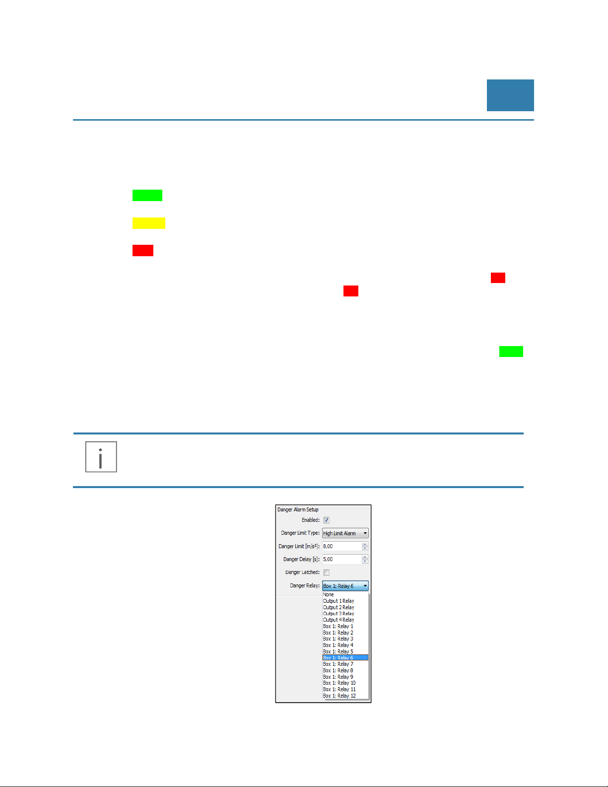
In Compact Setup make sure that the Relay Module feature is enabled: Edit / Monitor / Outputs / Relay Module
1 / Enabled – Mark box (= Yes). The LED on the front plate of the VC-1801 Relay Module should show green
light indicating that the VIBROCONTROL 18xx and the VC-1801 are communicating.
To set-up a stand-alone VIBROCONTROL 18xx there will be a listing of zero to four relays depending on how
many outputs have been assigned to be a relay.
As soon as a VC-1801 Relay Module has been connected to a VIBROCONTROL 18xx the above mentioned
listing is increased by twelve more relays.
One vibration parameter alarm can only have one relay associated with this alarm. An alarm
relay can be associated with one or more vibration parameter alarms.
© Brüel & Kjaer Vibro ● July 2018 ● C106834.002 / V02 ● █ Page 49 of 84
Technical alterations reserved!
Page 50
EN
Pre-Release
8.1.8 Connecting of a VIBROCONTROL 18xx and a VC-1801
The procedure is as follows:
Set the relay box select switch on the front panel of the VC-1801 to “Module 1” (or “Module 2”)
Mount the VIBROCONTROL 18xx and VC-1801 Relay Module together using the DIN-rail bus
connectors
Place the two modules on a 35 mm DIN rail
Connect the VIBROCONTROL 18xx to the 24 VDC main power
You will now see that the status LED on the front panel of the VC-1801 has a red colour
Connect the VIBROCONTROL 18xx to a PC that has the Compact Setup software installed
using e.g. a USB connection cable
In Compact Setup enable the Relay Module: Edit / Monitor / Outputs / Relay Module 1 / Enabled
– Mark box (= Yes)
In Compact Setup press “Apply”:
Edit / Apply, even though you have NOT changed any parameters
Note that the VC-1801 status LED changes colour from red to green.
One In the unlikely event that there is a loss of communication between the VIBROCONTROL
18xx and the VC-1801 Relay Module, the above described procedure may also be used to reestablish the communication between the two devices.
Page 50 of 84
Technical alterations reserved!
█ © Brüel & Kjaer Vibro ● July 2018 ● C106834.002 / V02
Page 51
© Brüel & Kjaer Vibro │Instruction VC-1800 series
Extension Modules for
VIBROCONTROL 1850/1860/1870
EN
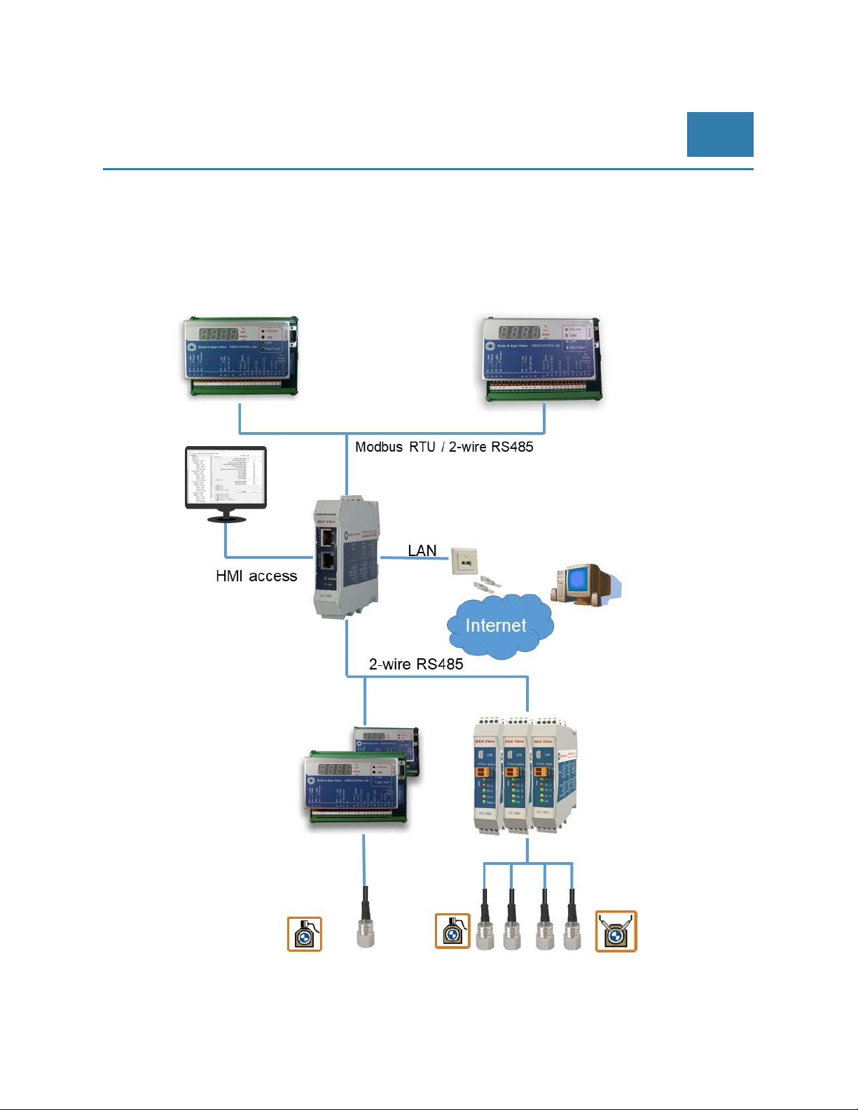
8.2 VIBROCONTROL 1803/1804 Communication Module - Etherbridge
8.2.1 Network
The VIBROCONTROL 1803/1804 is the interface between vibration monitor(s) that have their communication
ability (using RS232C or RS485) enabled and a remote PC (using LAN and/or the internet).
© Brüel & Kjaer Vibro ● July 2018 ● C106834.002 / V02 ● █ Page 51 of 84
Technical alterations reserved!
Page 52
EN
Pre-Release
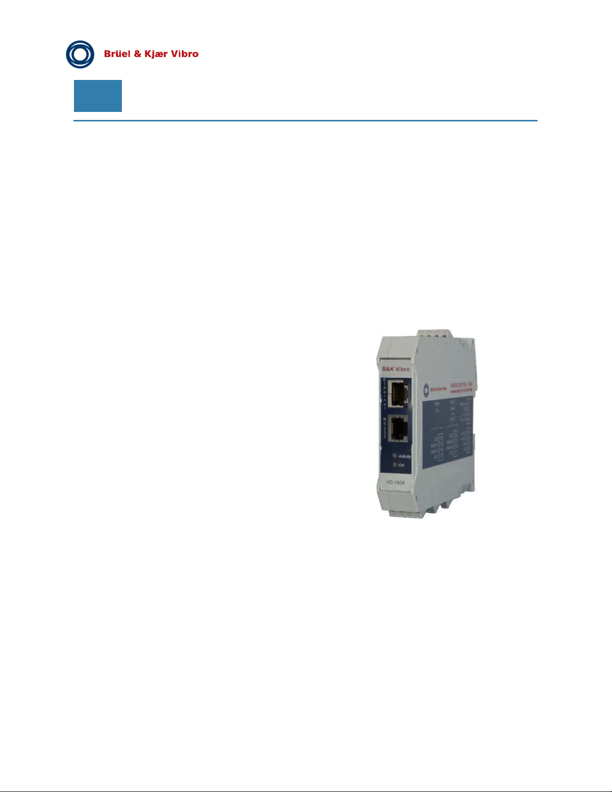
8.2.2 Applications
The VIBROCONTROL 1803/1804 allows communication between one or more vibration monitor(s) and one or
more remote PC(s) or PLC(s) in a local network (LAN) or – if required – over long distances via the internet.
Furthermore, the VIBROCONTROL 1804 includes data logging of measurement data and alarms for off-line
post analysis in Compact Commander Analyzer. Data logging is especially useful when an internet connection
and/or a local PC are not present.
Permanent cable installation is easily done by means of screw terminals. LAN and RS 232 connectors are
positioned in the front for better accessibility for frequent download of data or for later connection while in
operation.
Either of two COM-ports on the side of the device can be used for communications with each its own daisy
chain of Vibration monitors using a proprietary RS485 protocol.
8.2.3 Features
Communication hardware
RS 485, RS 485/232(Shared) and Ethernet
Communication protocols
Modbus RTU over Ethernet to RS 485/232
Modbus TCP converted to Modbus RTU
Modbus TCP converted to VC-18xx
OPC UA
Read/Write/Browse
Data storage (only VIBROCONTROL 1804)
Storage capacity 3 GB
Administrative features
Firmware upload
SLP Discovery (Service Local Discovery)
Configuration/Administration of the VIBROCONTROL 1803/1804 via HTTP (the device has its
own “homepage”)
Power supply: +24 VDC
Mounting: on a DIN Rail in an enclosure (recommended)
Dimensions: 120x110x23 mm
Housing: hard plastic, light grey RAL 7031
Page 52 of 84
Technical alterations reserved!
█ © Brüel & Kjaer Vibro ● July 2018 ● C106834.002 / V02
Page 53
© Brüel & Kjaer Vibro │Instruction VC-1800 series
Extension Modules for
VIBROCONTROL 1850/1860/1870
EN
8.2.4 Functionality
VIBROCONTROL 1803/1804 connects multiple Vibration Monitors to Ethernet and offers communication
protocols like Modbus TCP and OPC UA for HMI devices.
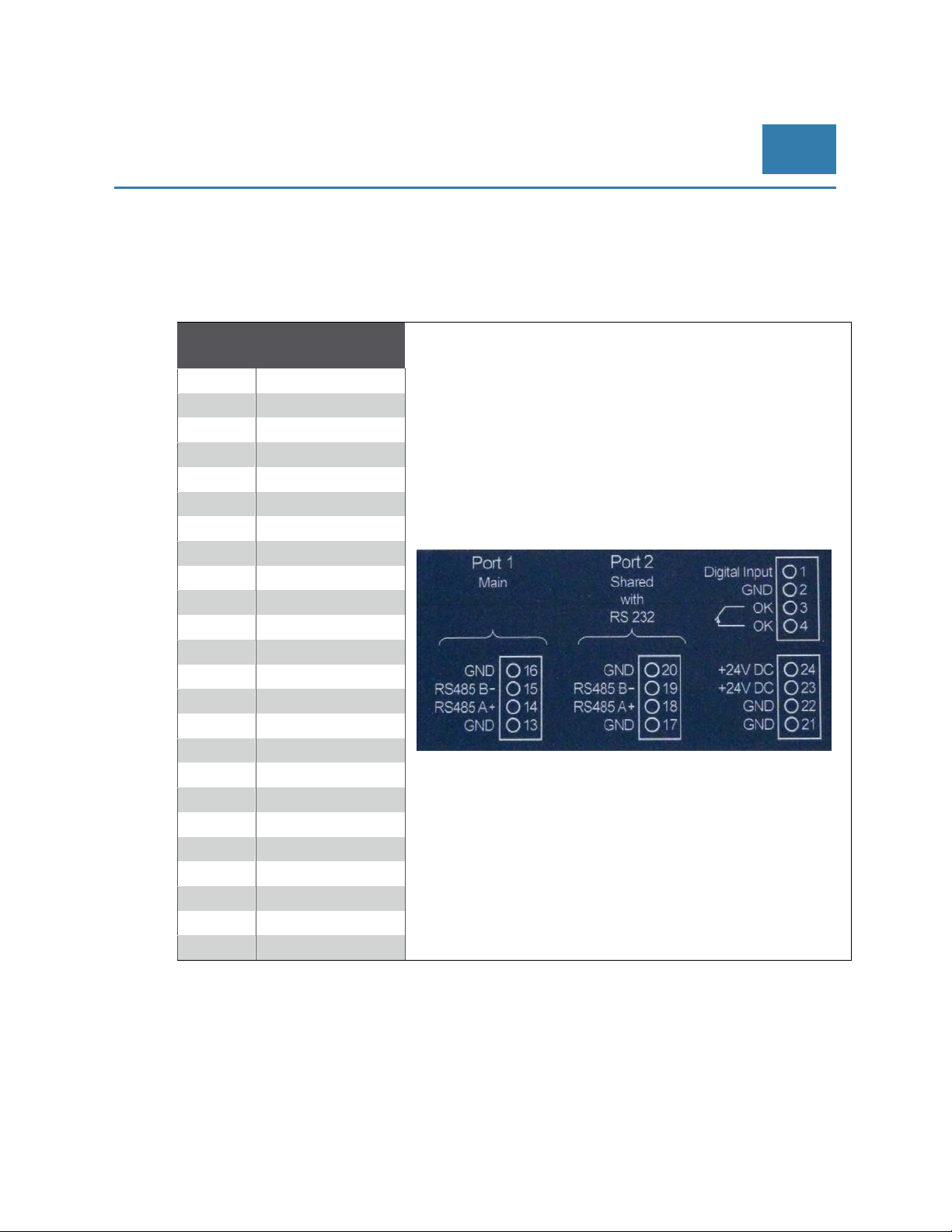
The screw terminals on the side are numbered from #1 to #24:
Terminal
#
1 Digital input
2 GND
3 Relay A
4 Relay B
5 NC
6 NC
7 NC
8 NC
9 NC
10 NC
11 NC
12 NC
13 GND
14 COM1 – RS485; A+
15 COM1 – RS485; B-
16 GND
17 GND
18 COM2 – RS485; A+
19 COM2 – RS485; B-
20 GND
21 GND
22 GND
23 + 24 VDC
24 + 24 VDC
Function
As described later in this manual the VIBROCONTROL 1803/1804 has two serial ports: COM1 (terminals #14
and #15) and COM2 (terminals #18 and #19). Both are used for RS485 communication with vibration monitors.
Screw terminals #21 to #24 are used to connect the VIBROCONTROL 1803/1804 to the 24 VDC of the main
power supply. There are two pairs of 24 VDC connections: “#21 and #22” plus “#23 and #24”.
We suggest to use one pair for connection to either the main power supply or the nearest powered module on
the DIN-rail. Use the second pair for connection to the nearest still unpowered module on the DIN-rail – if any.
In addition, there are two connectors on the top plate marked “Ethernet” and “RS232” respectively.
© Brüel & Kjaer Vibro ● July 2018 ● C106834.002 / V02 ● █ Page 53 of 84
Technical alterations reserved!
Page 54
EN
The Ethernet (LAN) connection is used for the permanent communication channel between the PC and the
VIBROCONTROL 1803/1804. The recommended connection cable is a standard LAN cable (CAT.5E).
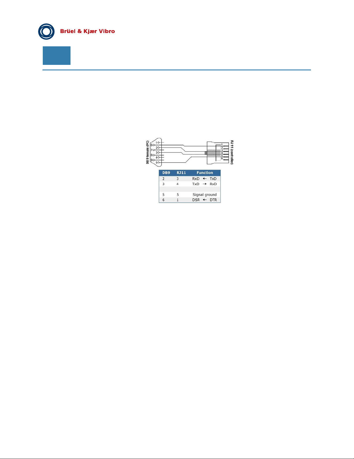
For the connection of measuring devices with RS232 connectors (VIBROCONTROL 950/960) use a female 9pin DB connector on one side (RS232 connector on vibration monitor) and a RJ11 connector on the other side
(RS232 connector on VIBROCONTROL 1803/1804).
Pre-Release
Page 54 of 84
Technical alterations reserved!
█ © Brüel & Kjaer Vibro ● July 2018 ● C106834.002 / V02
Page 55
© Brüel & Kjaer Vibro │Instruction VC-1800 series
Extension Modules for
VIBROCONTROL 1850/1860/1870
EN
8.2.5 Configuration of VIBROCONTROL 1803/1804
Upon delivery, the setup parameters of the VIBROCONTROL 1803/1804 are set to factory default values.
Connect the device to your local network (LAN) using a LAN-cable.
The device is default set to DHCP, which means that it will automatically get an IP address within the
boundaries related to the local network.
Any PC attached to the same network should now be able to “see” this device.
Any software capable of finding devices on a local network should be able to find the VIBROCONTROL
1803/1804 and disclose the actual IP address.
For configuration the Compact Setup Software is necessary.
8.2.5.1 Access to Webpage of VIBROCONTROL 1803/1804
To find out the IP address of VIBROCONTROL 1803/1804 use one of these methods.
If the IP address e.g. is 192.168.1.50, please use a web browser and enter the URL:
http://192.168.1.50.
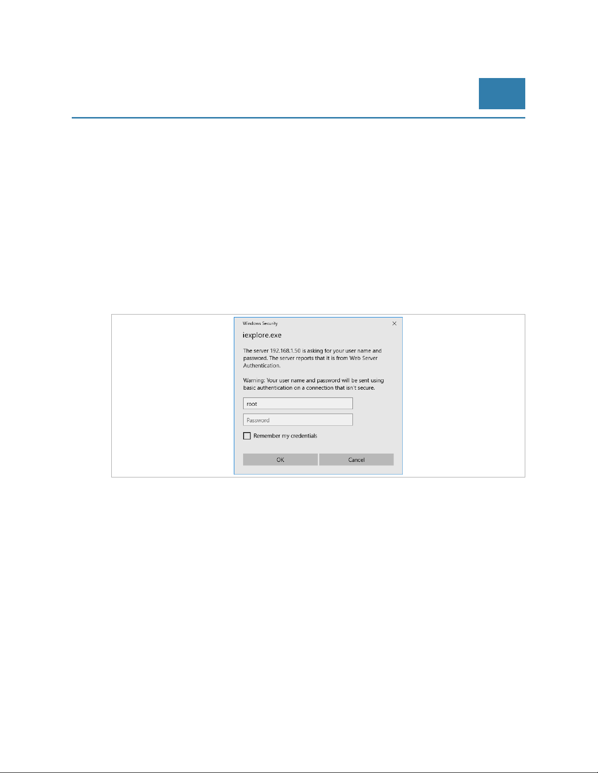
You will now be connected to the “homepage” of the device:
Enter the following data:
User name : root
Password : password
Click on OK to bring you to the next “Info” window.
If you mark “Remember my credentials”, you will be brought to the next Info window without re-typing the user
name and password.
© Brüel & Kjaer Vibro ● July 2018 ● C106834.002 / V02 ● █ Page 55 of 84
Technical alterations reserved!
Page 56
EN
Pre-Release
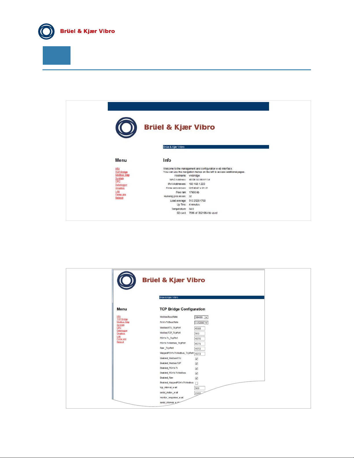
8.2.5.2 Menu: Info
This information window lists a number of the current parameters used by the device.
The MAC Address is a given value that can be changed only by the manufacturer
The IPv4 Address is the address provided by the DCHP procedure of set earlier under IPv4 Settings
in the System chapter of this manual.
8.2.5.3 Menu: TCP Bridge
Page 56 of 84
Technical alterations reserved!
█ © Brüel & Kjaer Vibro ● July 2018 ● C106834.002 / V02
Page 57

© Brüel & Kjaer Vibro │Instruction VC-1800 series
The VC-1803/04 has basically two paths to communicate with the outside world:
Modbus
Modbus communication covers the data transfer between the VC-1803/04 and the PC via a LAN
connection
The ModbusBaudRate is the speed of the communication between the LAN (PC) and the
VC-1803/04. It is default set to 38400 and should only be changed if absolutely necessary.
There are two possible ways of Modbus communication each having their own PCP-port:
- ModbusRTU: Enabled by setting a mark at Enabled_ModbusRTU and using TCP-port
ModbusRTU_TcpPort, which is 4568 by default
- ModbusTCP: Enabled by setting a mark at Enabled_ModbusTCP and using TCP-port
ModbusTCP_TcpPort, which is 502 by default
Please make sure that the default choice of TCP-ports is not in conflict with the ports of any other device
already connected to the local network.
Serial (PCH1x7x)
Serial communication covers the data transfer between the VC-1803/04 and the vibration
monitor(s) via a RS232C connection (one vibration monitor only) or a RS485 connection (one or
more vibration monitors).
Extension Modules for
VIBROCONTROL 1850/1860/1870
EN
The Pch1x7xBaudRate is the speed of communication between the “slowest” vibration monitor and the VC1803/04. It is default set to 115200 and should only be changed if absolutely necessary.
There are two possible ways of serial communication each having their own PCP-port:
- PCH1x7x: Enabled by setting a mark at Enabled_PCH1x7x and using TCP-port
PCH1x7x_TcpPort, which is 4570 by default
- PCH1x7xModbus: Enabled by setting a mark at Enabled_PCH1x7xModbus and using TCP- port
PCH1x7xModbus_TcpPort, which is 4571 by default
Please make sure that the default choice of TCP-ports is not in conflict with the ports of any other device
already connected to the local network.
The tcp_interval_wait indicates the maximum time (ms) allowed between the data packs in TCP mode. If this
value is exceeded a time-out error will be the result.
The serial_mutex_wait indicates the maximum time (ms) allowed for the UART (RS232 or RS485) before it is
ready for action (again). If this value is exceeded a time-out error will be the result.
The monitor_response_wait indicates the maximum time (ms) the VC-1803/04 will wait for a response from a
certain attached vibration monitor after the device has sent a data-request to this monitor. If this value is
exceeded a time-out error will be the result.
The modbus_interval_wait indicates the maximum time (ms) allowed between the data packs in serial mode. If
this value is exceeded a time-out error will be the result.
The VC-1803/04 has two COM-ports available for serial communication with the vibration monitors. Only one
COM-port may be used at any time. By choosing “None”, the COM- port on the top panel will act as a RS232C
connection.
© Brüel & Kjaer Vibro ● July 2018 ● C106834.002 / V02 ● █ Page 57 of 84
Technical alterations reserved!
Page 58
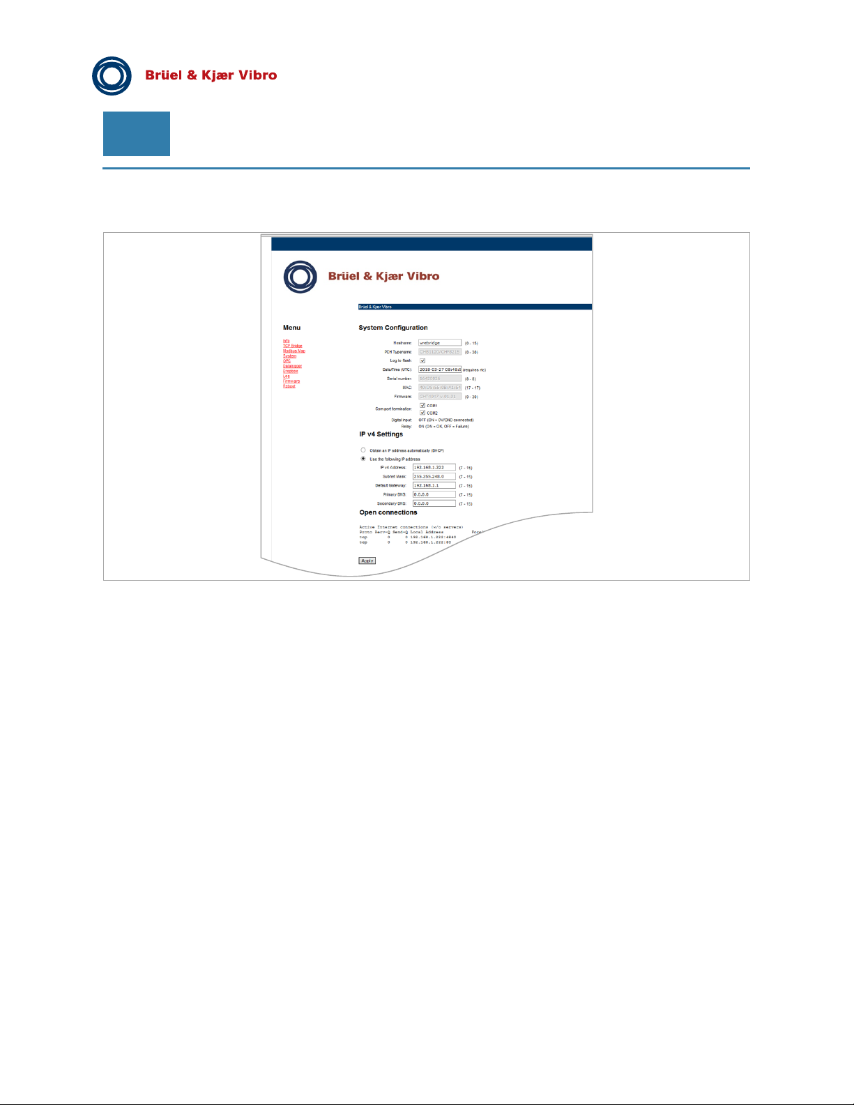
EN
Pre-Release
8.2.5.4 Menu: System
The System page of the VC-1803/04 “homepage” allows the setting or reading of a few general parameter
settings:
- Hostname: At this position the user is free to enter a relevant name for the device
- PCH Typename: The name given to the device by the manufacturer. The user has no influence
on this read-only parameter
- Log to flash: By marking Log to flash the log file will be stored in the internal flash memory of the
device
- Date/Time: At this position the user can set the date and time that will be displayed in connection
with data logging. Please note that Date/Time will be reset to its default value (2007-01-01
00:00:24) each time the power has been removed from the device.
- Serial number: The number shown here is the serial number of the device as it was set by the
manufacturer prior to shipment. The user has no influence on this read-only parameter
- MAC: The unique number of the device in cyber space entered by the manufacturer. The user
has no influence on this read-only parameter
- Firmware: Here the firmware version of the device is shown. It is possible to change the firmware
of the device using a procedure described in the chapter Firmware.
In addition this page is also used to control the IP v4 address of the device. By default the unique IP address is
provided automatically by the host of the local network (DHCP).
However, the user has the possibility to force the device to have a certain fixed IP v4 address. This requires
that the following parameters must be entered:
- IP v4 address: “A.B.C.D” is the unique address of the device in the local network, where A, B and
C are the same as for the Gateway. “D” may be any number between 2 and 255, but NOT be
equal to any other device in the local network. Please check available numbers for “D” before
entering a value her
- Subnet Mask: Normally “255.255.255.0”
Page 58 of 84
Technical alterations reserved!
█ © Brüel & Kjaer Vibro ● July 2018 ● C106834.002 / V02
Page 59
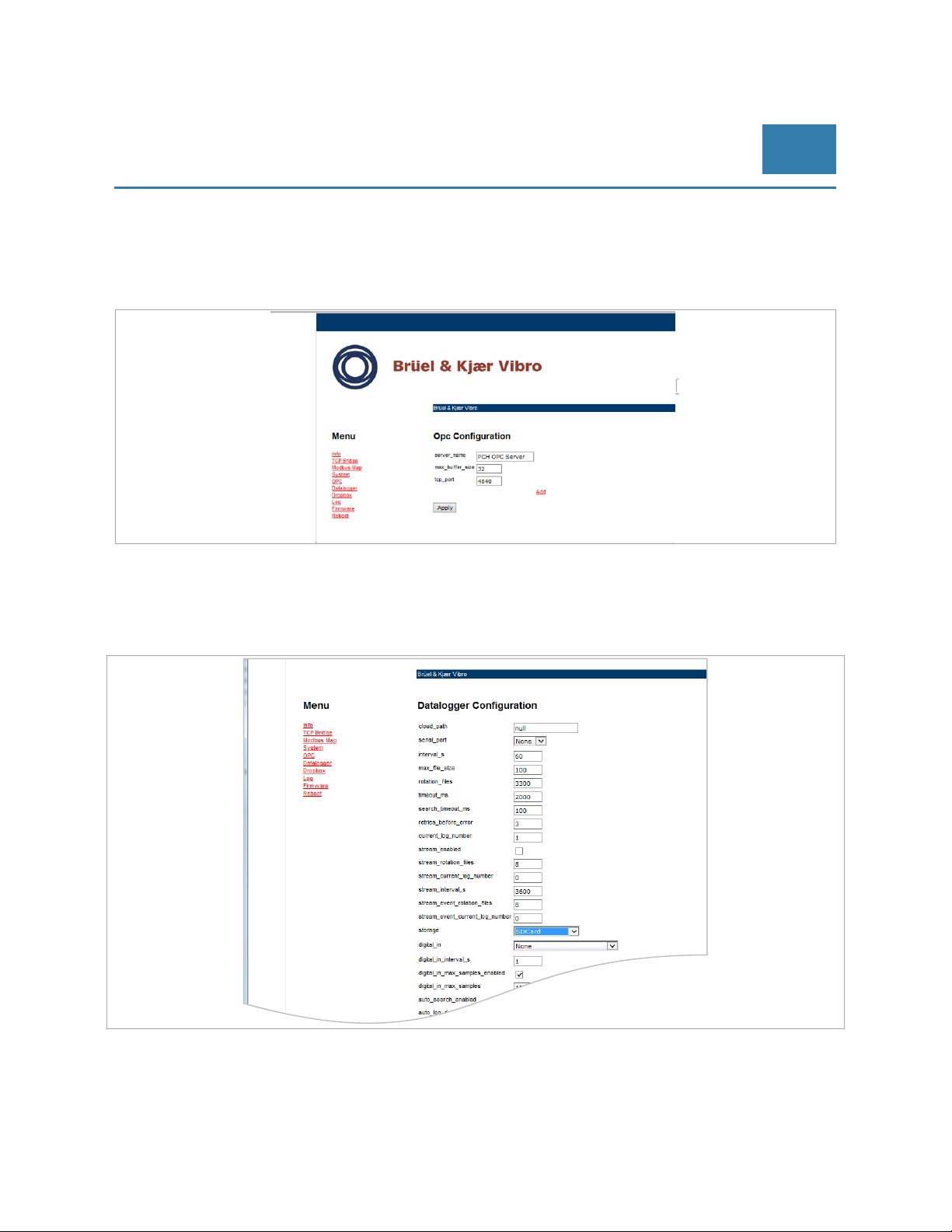
© Brüel & Kjaer Vibro │Instruction VC-1800 series
- Default Gateway: “A.B.C.1” is the address of the host in the local network. If you don’t know this
address, please ask your IT Manager
- Primary DNS: The default value of “0.0.0.0” is usually adequate
- Secondary DNS: The default value of “0.0.0.0” is usually adequate
8.2.5.5 Menu: OPC
Extension Modules for
VIBROCONTROL 1850/1860/1870
EN
The VC-1803/04 can be used in an OPC environment. The parameter settings on this page are provided by the
manufacturer upon shipment of the device and should not be changed unless advised by the manufacturer
after consultation.
8.2.5.6 Menu: Data logger (VC-1804 only)
Only the VC-1804 has a data logging feature that allows storage of data from either the RS232 port, the COM1
port or the COM2 port. The data logging is enabled by marking Log to flash in the System window.
© Brüel & Kjaer Vibro ● July 2018 ● C106834.002 / V02 ● █ Page 59 of 84
Technical alterations reserved!
Page 60
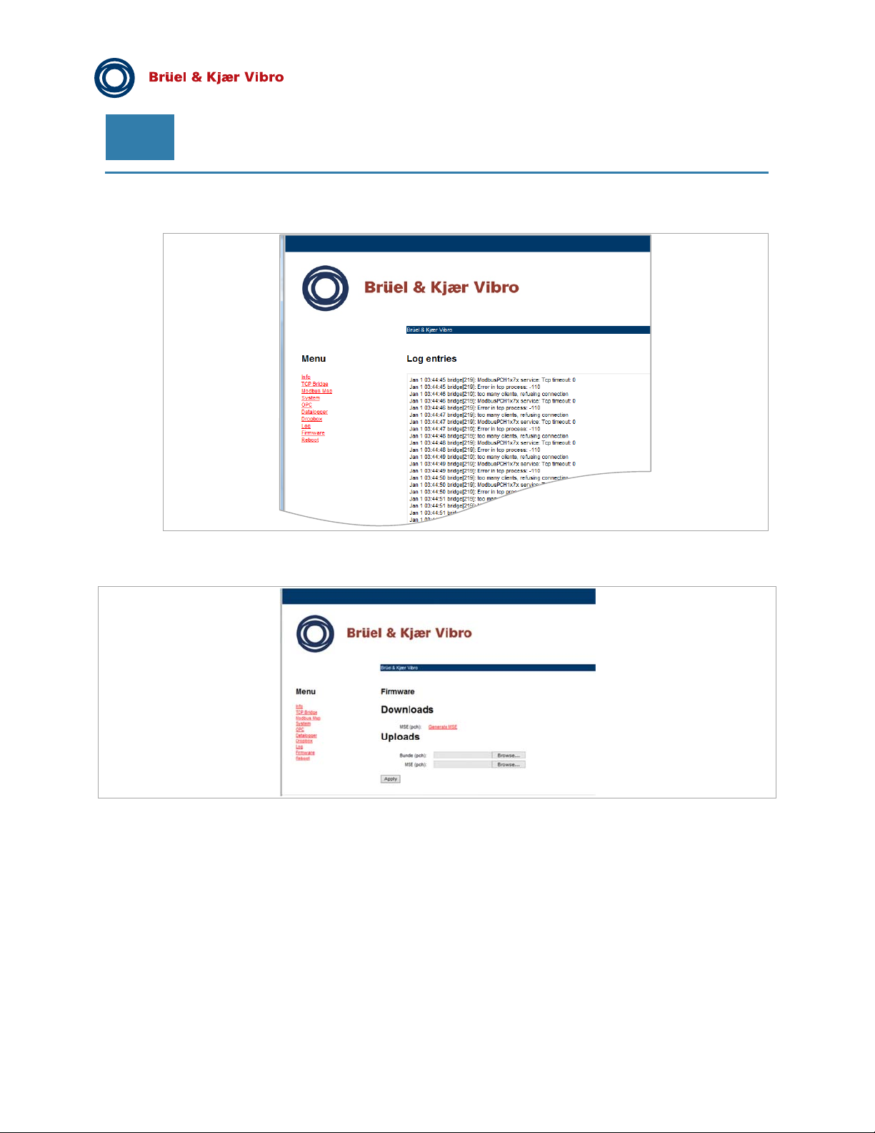
EN
Pre-Release
8.2.5.7 Menu: Log
This is a log file for debugging purposes. There is no useful measurement data for the user on this page.
8.2.5.8 Menu: Firmware
The firmware page should only be visited if the user must upload a new firmware version for the VC-1803/04
and has received a bundle of necessary (.BDL and/or .MSE) files from the manufacturer. Store these files on
your HDD for later use.
There are two different files available for an update:
- Bundle (pch): Enter here the path where you stored the .BDL firmware data file from the
manufacturer
- MSE (pch): Enter here the path where you stored the .MSE parameter setup data file from the
manufacturer or one you stored earlier
If the device is functioning properly the user may store the current parameter settings of the device under
“Downloads” to generate a .MSE parameter setup data file using the following procedure:
- Click on Generate MSE
- You will now see the complete content of the .MSE file
- Mark the entire text content
Page 60 of 84
Technical alterations reserved!
█
© Brüel & Kjaer Vibro ● July 2018 ● C106834.002 / V02
Page 61
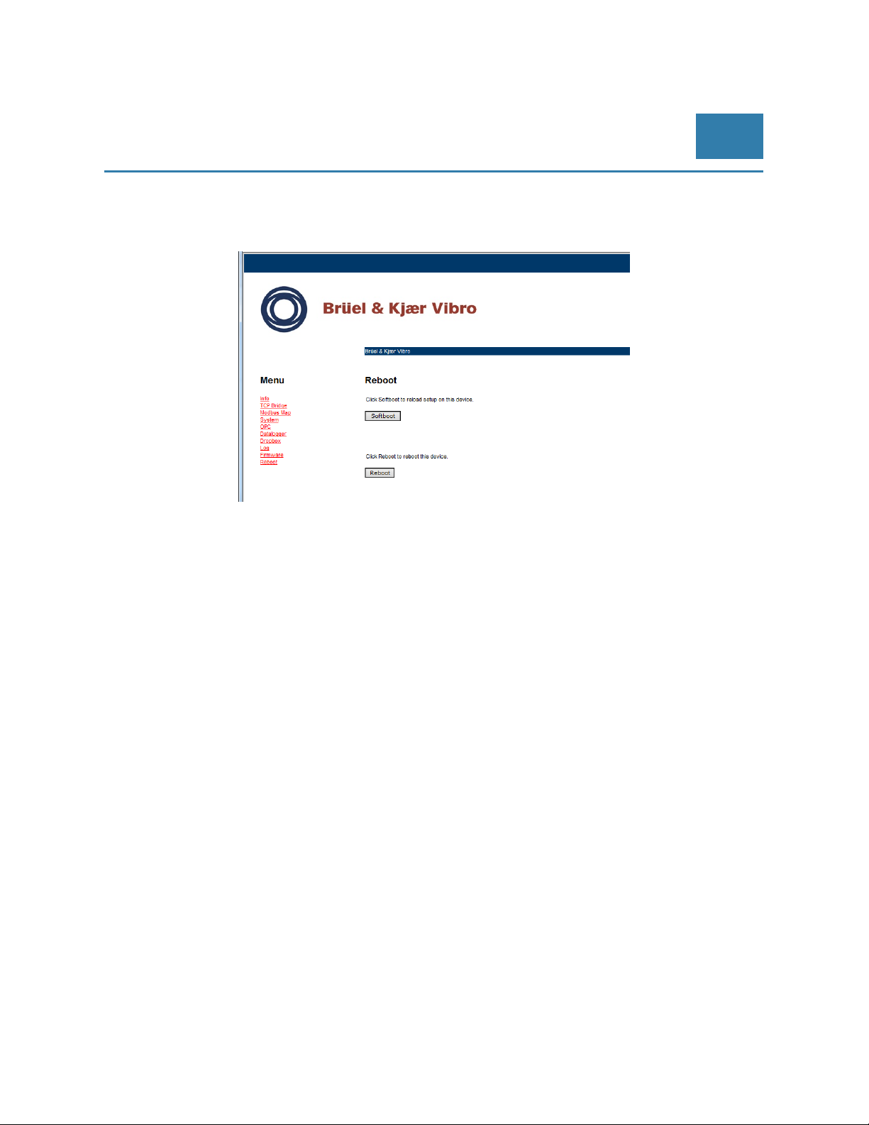
© Brüel & Kjaer Vibro │Instruction VC-1800 series
- Click on the “Send to OneNote” icon on the top of the screen
- Select the OneNote section where to put the .MSE file
8.2.5.9 Menu: Reboot
Extension Modules for
VIBROCONTROL 1850/1860/1870
EN
Any changes made to the parameter setup of the VC-1803/04 will only be implemented after a forced reboot of
the device.
To initialise the reboot process, please click on the Reboot button. You will see that the green Status LED on
the top of the enclosure flashes during the reboot process. As soon as the Status LED stops flashing the new
parameters have been uploaded and now are implemented in the device.
© Brüel & Kjaer Vibro ● July 2018 ● C106834.002 / V02 ● █ Page 61 of 84
Technical alterations reserved!
Page 62
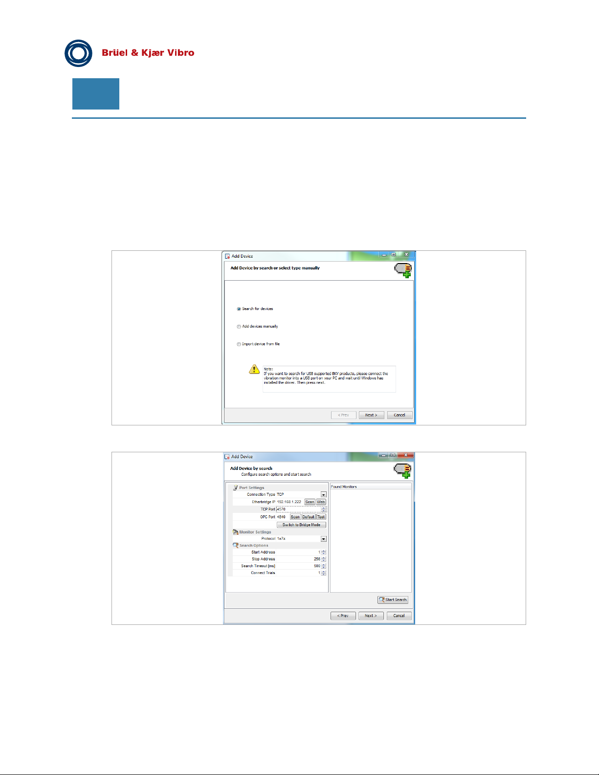
EN
Pre-Release
8.2.6 VIBROCONTROL 1803/04 with Compact Setup
The VIBROCONTROL 1800 vibration monitors can be connected to the PC running the software in different
ways:
- Directly to a PC via USB port or RS-485. This method is mainly used for temporary connection of
a fixed mounted VC-1800 and a (notebook PC) in the field, e.g. to upgrade (new firmware) or to
update (new setup parameter(s)). This way the PC can only control one monitor at the time.
- As part of a PC controlled RS485 chain of VC-1800 vibration monitors
- Through a local network (LAN) via a VC-1803/04
After start-up of the Compact Setup Software, please use “Add Device”:
If it does not show the correct communication type, mark this line and press the “Next” button for editing.
The “Edit Port Settings” screen will pop up.
Click on the “Communication Type” field and chose “Etherbridge”
When the search is finished you will see a listing of all VC-1803/04s in the local network.
Page 62 of 84
Technical alterations reserved!
█ © Brüel & Kjaer Vibro ● July 2018 ● C106834.002 / V02
Page 63
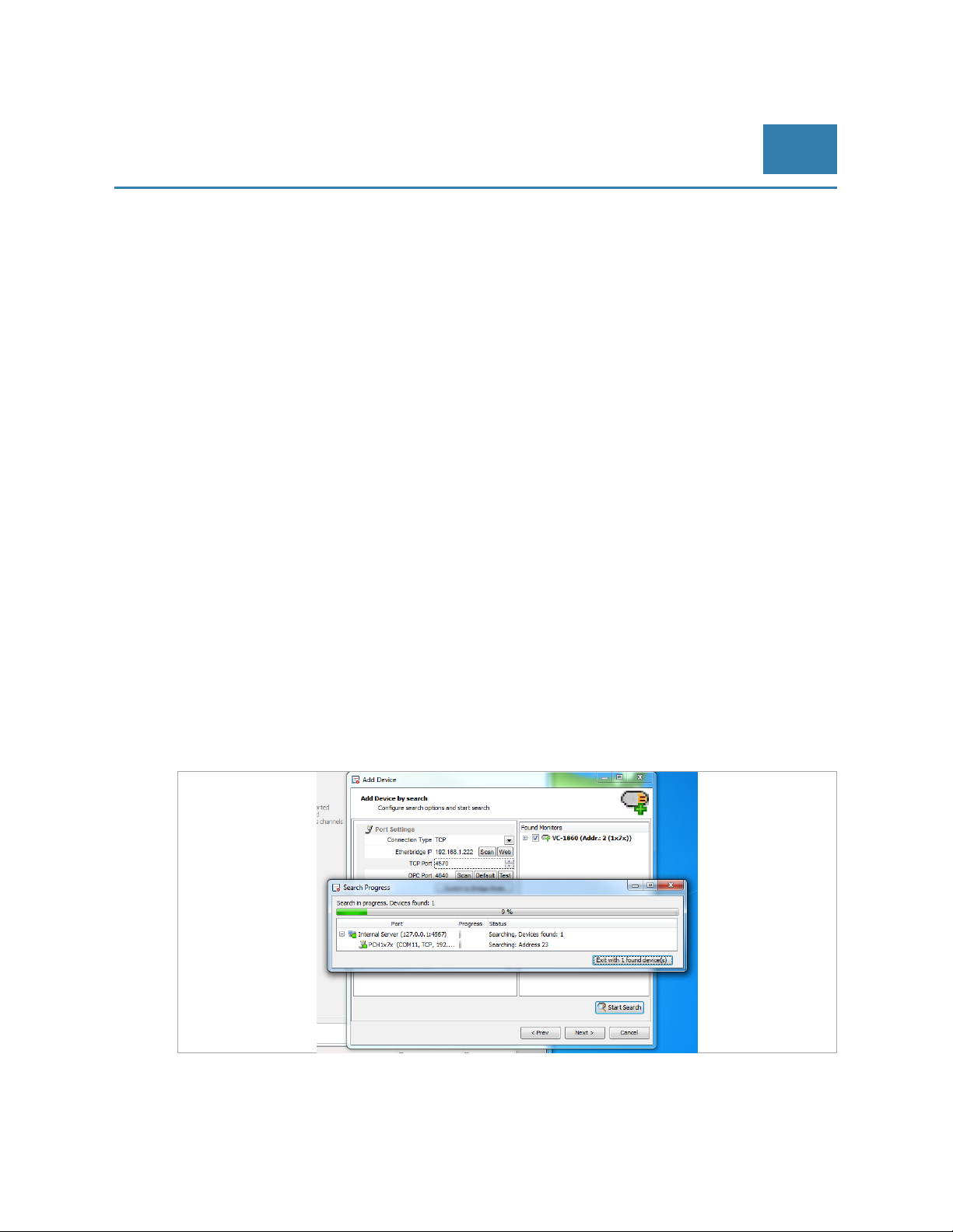
© Brüel & Kjaer Vibro │Instruction VC-1800 series
Click on the line with the relevant device, which then will turn blue. Click the “Select” button.
Before it is possible to find the vibration monitors via their RS232 connector it is necessary to make sure that
the RS232 feature of the VC-1803/04 is enabled.
Click on the “Etherbridge Web” button, which will bring you to the Windows Security screen.
RS232 is enabled together with RS485 on COM2. Therefore click on “com_port” and choose COM2. Click on
the “Apply” button.
RS485 is enabled either on COM1 or COM2 (not both at the same time!) Therefore click on “com_port” and
choose “COM1” or “COM2”.
Click on the “Apply” button.
For final implementation it is not enough to “Apply” the new settings. It is essential to reboot the VC-1803/04 in
order to implement any applied new settings.
To initialise the reboot procedure, please click on “Reboot” and wait until the green “Status” LED has stopped
flashing.
RS232: Connect your vibration monitor (“RS232” marked DB9 connector) to the VC-1803/04 (“RS232” marked
RJ11 connector on the top cover plate).
RS485: Connect your RS485 chain of vibration monitors to either the screw terminal COM1 or COM 2 on the
side of the VC-1803/04 enclosure.
If COM2 is used for RS485, please leave the RS232 connector on the top plate free (= unattached) and vice
versa. To use both serial modes simultaneously is not official supported by the manufacturer.
Leave the “Bridge Configuration” screens and return to the edit port settings screen of the software.
Make sure that the Etherbridge IP is the correct one.
Press the “Apply” button followed by pressing the “OK” button to return to the “Monitor Initialization Wizard”, but
now with the correct communication settings mentioned:
Extension Modules for
VIBROCONTROL 1850/1860/1870
EN
Mark “Search for Monitor” and click the “Next” button. The next screen is the “Search for Monitor” screen.
© Brüel & Kjaer Vibro ● July 2018 ● C106834.002 / V02 ● █ Page 63 of 84
Technical alterations reserved!
Page 64
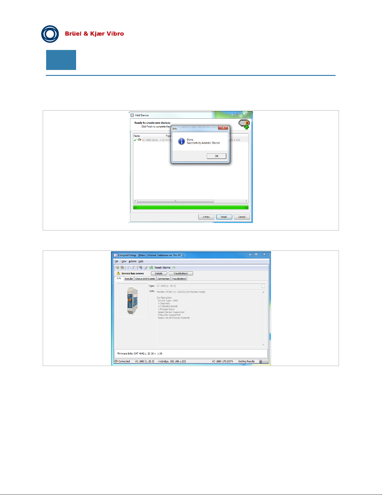
EN
Start the search for attached vibration monitor(s) by pressing the “Start Search” button.
At first the Baud rate is fixed to an appropriate speed. Fixing the Baud rate might take some time.
Pre-Release
Now measuring units VIBROCONTROL-18xx are connected through the VC-1803/04.
Page 64 of 84
Technical alterations reserved!
█ © Brüel & Kjaer Vibro ● July 2018 ● C106834.002 / V02
Page 65
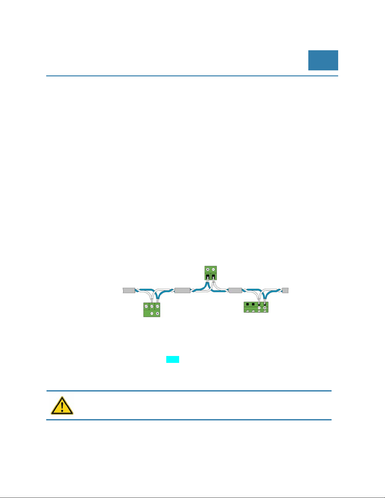
© Brüel & Kjaer Vibro │Instruction VC-1800 series
Connecting the VIBROCONTROL
18xx to a PLC/PC
EN
9 Connecting the VIBROCONTROL 18xx to a PLC/PC
The VIBROCONTROL 18xx Vibration Monitor is provided with a RS-485 and an USB 2.0 interface, which
allows the user to change many of the setup parameters if connected to a PLC or PC with suitable software
installed. The same interfaces can also be used to read out a number of registers inside the vibration monitor
with status information or the actual level of a large number of vibration measuring functions. The PC software
used for this purpose is called Compact Setup Software.
The VIBROCONTROL 18xx Vibration Monitor is delivered with a pre-configured setup. The Compact Setup
Software will overwrite this setup when it is used to change the changeable parameters in the device.
9.1 USB 2.0 interface
To use the USB 2.0 interface, connect the USB cable between the VIBROCONTROL 18xx Vibration Monitor
and a USB port on the computer. The maximum data transfer speed between a PC and a VIBROCONTROL
18xx device is 3 MBaud.
9.2 RS-485 interface
The VIBROCONTROL 18xx Vibration Monitor allows “multi-drop”, i.e. up to 255 devices can be addressed
individually in a RS-485 chain of devices.
To use the RS-485 interface, connect the yellow connector (marked: “RS-485”) at the front panel of the
VIBROCONTROL 18xx enclosure to the RS-485 chain of devices using a two wire twisted and shielded cable.
The cable must be terminated with a 120 Ω resistor in both ends, i.e. on the PC side and at the last device on
the RS-485 chain of devices. The VIBROCONTROL 18xx Vibration Monitor has a built-in 120 Ω termination
resistor, which can be used for this purpose. To switch the termination resistor ON, use the small left/right
sliding switch behind a small hole at the front panel of the VIBROCONTROL 18xx enclosure. Soon after the
termination resistor has been switched, ON a Blue LED at the front panel of the VIBROCONTROL 18xx will
indicate that the 120 Ω termination resistor is in place.
The maximum data transfer speed between the PC and the VIBROCONTROL 18xx is 115 kBaud.
Please make sure that you do not add a new device to your FieldBus that has an address
occupied by another device already present in the RS-485 chain of devices.
© Brüel & Kjaer Vibro ● July 2018 ● C106834.002 / V02 ●
Technical alterations reserved!
█
Page 65 of 84
Page 66
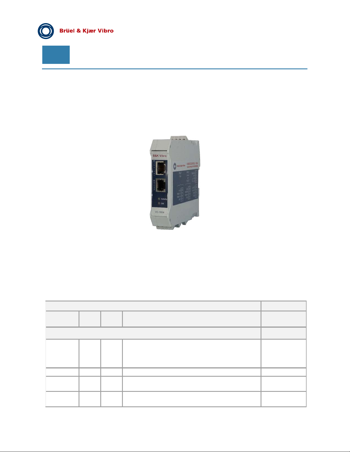
EN
Pre-Release
9.3 VIBROCONTROL 1803/04 LAN interface
The VIBROCONTROL 18xx can also be remotely operated using a LAN connection. This requires the use of
an additional VIBROCONTROL 1803 communication module.
The VIBROCONTROL 1803 module is on one side connected to a PC Ethernet network with a LAN cable. The
other side of VC-1803 is connected to the yellow RS-485 connector at the front panel of the
VIBROCONTROL 18xx enclosure marked “RS-485” using a two wire twisted and shielded cable.
9.4 Modbus Connection for VIBROCONTROL 18xx via 1803/04
Modbus Address and Register
The following tables specify the ModbusTCP address for the registers contained in a given VIBROCONTROL
18xx monitor. A register consists of 2 bytes. Please notice that an address can also be halved. e.g. address
"1000,5". This means that the register will not start at the first byte, but at the second. The “second” byte is the
LSB in a Big Endian Word. Proper conversion will also make it the LSB in Little Endian, thereby converting it to
the “first” byte instead. Be mindful of this.
Flash data (Read only)
status
Modbus
address
General critical registers, must be read:
40000
29738 2 s32 ccw_flash [OK: 0x20300] CCW = 0x2030
40006 0.5 u8 system_failure_relay [OK: state = 0] No Alarm = 0 Alarm
40019.5 0.5 u8 transducer_input_1.overload [OK: Overload_state=0] Overload_state = 0
Register
length
0.5
Register
type Register name
U8
status_code [OK: Monitoring_state=6]
Error_state = 3
Settling_state = 4
Self_test_state=5
Monitoring_state=6
= 1
Overload_state = 1
Page 66 of 84
Technical alterations reserved!
█ © Brüel & Kjaer Vibro ● July 2018 ● C106834.002 / V02
Page 67
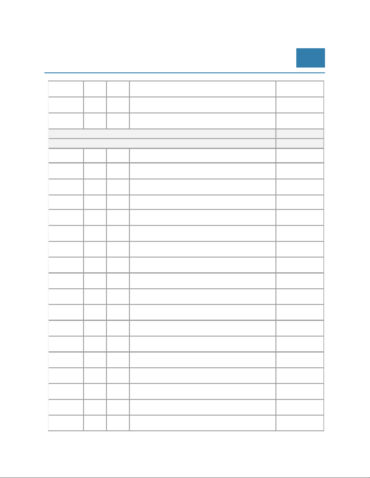
© Brüel & Kjaer Vibro │Instruction VC-1800 series
_
_
Connecting the VIBROCONTROL
18xx to a PLC/PC
EN
40046.5 0.5 u8 transducer_input_2.overload [OK: Overload_state=0] Overload_state = 0
Overload
40073.5 0.5 u8 transducer_input_3.overload [OK: Overload_state=0] Overload_state = 0
Overload_state = 1
40100.5 0.5 u8 transducer_input_4.overload [OK: Overload_state=0] Overload_state = 0
Overload
Optional registers to be read:
Transducer 1:
40021 2 float transducer_input_1.band_1.vibration_detector.measuring_result
state = 1
state = 1
40023 0.5 u8 transducer_input_1.band_1.vibration_detector.alert_alarm No Alarm = 0 Alarm
40023.5 0.5 u8 transducer_input_1.band_1.vibration_detector.danger_alarm No Alarm = 0 Alarm
40024 2 float transducer_input_1.band_2.vibration_detector.measuring_result
40026 0.5 u8 transducer_input_1.band_2.vibration_detector.alert_alarm No Alarm = 0 Alarm
40026.5 0.5 u8 transducer_input_1.band_2.vibration_detector.danger_alarm No Alarm = 0 Alarm
40027 2 float transducer_input_1.band_2.envelope_detector_1.measuring_re
sult
40029 0.5 u8 transducer_input_1.band_2.envelope_detector_1.alert_alarm No Alarm = 0 Alarm
40029.5 0.5 u8 transducer_input_1.band_2.envelope_detector_1.danger_alarm No Alarm = 0 Alarm
40030 2 float transducer_input_1.band_2.envelope_detector_2.measuring_re
sult
40032 0.5 u8 transducer_input_1.band_2.envelope_detector_2.alert_alarm No Alarm = 0 Alarm
40032.5 0.5 u8 transducer_input_1.band_2.envelope_detector_2.danger_alarm No Alarm = 0 Alarm
40033 2 float transducer_input_1.band_2.crest_factor_detector.measuring_re
sult
40035 0.5 u8 transducer_input_1.band_2.crest_factor_detector.alert_alarm No Alarm = 0 Alarm
40035.5 0.5 u8 transducer_input_1.band_2.crest_factor_detector.danger_alarm No Alarm = 0 Alarm
40036 2 float transducer_input_1.band_2.kurtosis_detector.measuring_result
= 1
= 1
= 1
= 1
= 1
= 1
= 1
= 1
= 1
= 1
40038 0.5 u8 transducer_input_1.band_2.kurtosis_detector.alert_alarm No Alarm = 0 Alarm
40038.5 0.5 u8 transducer_input_1.band_2.kurtosis_detector.danger_alarm No Alarm = 0 Alarm
© Brüel & Kjaer Vibro ● July 2018 ● C106834.002 / V02 ● █ Page 67 of 84
Technical alterations reserved!
= 1
= 1
Page 68
EN
Pre-Release
Transducer 2:
40048 2 float transducer_input_2.band_1.vibration_detector.measuring_result
40050 0.5 u8 transducer_input_2.band_1.vibration_detector.alert_alarm No Alarm = 0 Alarm
40050.5 0.5 u8 transducer_input_2.band_1.vibration_detector.danger_alarm No Alarm = 0 Alarm
40051 2 float transducer_input_2.band_2.vibration_detector.measuring_result
40053 0.5 u8 transducer_input_2.band_2.vibration_detector.alert_alarm No Alarm = 0 Alarm
40053.5 0.5 u8 transducer_input_2.band_2.vibration_detector.danger_alarm No Alarm = 0 Alarm
40054 2 float transducer_input_2.band_2.envelope_detector_1.measuring_re
sult
40056 0.5 u8 transducer_input_2.band_2.envelope_detector_1.alert_alarm No Alarm = 0 Alarm
40056.5 0.5 u8 transducer_input_2.band_2.envelope_detector_1.danger_alarm No Alarm = 0 Alarm
40057 2 float transducer_input_2.band_2.envelope_detector_2.measuring_re
sult
40059 0.5 u8 transducer_input_2.band_2.envelope_detector_2.alert_alarm No Alarm = 0 Alarm
40059.5 0.5 u8 transducer_input_2.band_2.envelope_detector_2.danger_alarm No Alarm = 0 Alarm
40060 2 float transducer_input_2.band_2.crest_factor_detector.measuring_re
sult
40062 0.5 u8 transducer_input_2.band_2.crest_factor_detector.alert_alarm No Alarm = 0 Alarm
40062.5 0.5 u8 transducer_input_2.band_2.crest_factor_detector.danger_alarm No Alarm = 0 Alarm
40063 2 float transducer_input_2.band_2.kurtosis_detector.measuring_result
= 1
= 1
= 1
= 1
= 1
= 1
= 1
= 1
= 1
= 1
40065 0.5 u8 transducer_input_2.band_2.kurtosis_detector.alert_alarm No Alarm = 0 Alarm
40065.5 0.5 u8 transducer_input_2.band_2.kurtosis_detector.danger_alarm No Alarm = 0 Alarm
= 1
= 1
Page 68 of 84
Technical alterations reserved!
█ © Brüel & Kjaer Vibro ● July 2018 ● C106834.002 / V02
Page 69
© Brüel & Kjaer Vibro │Instruction VC-1800 series
A
A
A
A
Connecting the VIBROCONTROL
18xx to a PLC/PC
Transducer 3:
40075 2 float transducer_input_3.band_1.vibration_detector.measuring_result
EN
40077 0.5 u8 transducer_input_3.band_1.vibration_detector.alert_alarm No Alarm = 0 Alarm
40077.5 0.5 u8 transducer_input_3.band_1.vibration_detector.danger_alarm No Alarm = 0 Alarm
40078 2 float transducer_input_3.band_2.vibration_detector.measuring_result
40080 0.5 u8 transducer_input_3.band_2.vibration_detector.alert_alarm No Alarm = 0 Alarm
40080.5 0.5 u8 transducer_input_3.band_2.vibration_detector.danger_alarm No Alarm = 0 Alarm
40081 2 float transducer_input_3.band_2.envelope_detector_1.measuring_re
sult
40083 0.5 u8 transducer_input_3.band_2.envelope_detector_1.alert_alarm No Alarm = 0 Alarm
40083.5 0.5 u8 transducer_input_3.band_2.envelope_detector_1.danger_alarm No Alarm = 0 Alarm
40084 2 float transducer_input_3.band_2.envelope_detector_2.measuring_re
sult
40086 0.5 u8 transducer_input_3.band_2.envelope_detector_2.alert_alarm No Alarm = 0 Alarm
40086.5 0.5 u8 transducer_input_3.band_2.envelope_detector_2.danger_alarm No Alarm = 0 Alarm
40087 2 float transducer_input_3.band_2.crest_factor_detector.measuring_re
sult
40089 0.5 u8 transducer_input_3.band_2.crest_factor_detector.alert_alarm No Alarm = 0
40089.5 0.5 u8 transducer_input_3.band_2.crest_factor_detector.danger_alarm No Alarm = 0
40090 2 float transducer_input_3.band_2.kurtosis_detector.measuring_result
= 1
= 1
= 1
= 1
= 1
= 1
= 1
= 1
larm = 1
larm = 1
40092 0.5 u8 transducer_input_3.band_2.kurtosis_detector.alert_alarm No Alarm = 0
40092.5 0.5 u8 transducer_input_3.band_2.kurtosis_detector.danger_alarm No Alarm = 0
larm = 1
larm = 1
© Brüel & Kjaer Vibro ● July 2018 ● C106834.002 / V02 ● █ Page 69 of 84
Technical alterations reserved!
Page 70
EN
A
A
A
A
A
A
A
A
A
A
A
A
Pre-Release
Transducer 4:
40102 2 float transducer_input_4.band_1.vibration_detector.measuring_result
40104 0.5 u8 transducer_input_4.band_1.vibration_detector.alert_alarm No Alarm = 0
40104.5 0.5 u8 transducer_input_4.band_1.vibration_detector.danger_alarm No Alarm = 0
40105 2 float transducer_input_4.band_2.vibration_detector.measuring_result
40107 0.5 u8 transducer_input_4.band_2.vibration_detector.alert_alarm No Alarm = 0
40107.5 0.5 u8 transducer_input_4.band_2.vibration_detector.danger_alarm No Alarm = 0
40108 2 float transducer_input_4.band_2.envelope_detector_1.measuring_re
sult
40110 0.5 u8 transducer_input_4.band_2.envelope_detector_1.alert_alarm No Alarm = 0
40110.5 0.5 u8 transducer_input_4.band_2.envelope_detector_1.danger_alarm No Alarm = 0
40111 2 float transducer_input_4.band_2.envelope_detector_2.measuring_re
sult
40113 0.5 u8 transducer_input_4.band_2.envelope_detector_2.alert_alarm No Alarm = 0
40113.5 0.5 u8 transducer_input_4.band_2.envelope_detector_2.danger_alarm No Alarm = 0
40114 2 float transducer_input_4.band_2.crest_factor_detector.measuring_re
sult
40116 0.5 u8 transducer_input_4.band_2.crest_factor_detector.alert_alarm No Alarm = 0
40116.5 0.5 u8 transducer_input_4.band_2.crest_factor_detector.danger_alarm No Alarm = 0
40117 2 float transducer_input_4.band_2.kurtosis_detector.measuring_result
larm = 1
larm = 1
larm = 1
larm = 1
larm = 1
larm = 1
larm = 1
larm = 1
larm = 1
larm = 1
40119 0.5 u8 transducer_input_4.band_2.kurtosis_detector.alert_alarm No Alarm = 0
40119.5 0.5 u8 transducer_input_4.band_2.kurtosis_detector.danger_alarm No Alarm = 0
larm = 1
larm = 1
Page 70 of 84
Technical alterations reserved!
█ © Brüel & Kjaer Vibro ● July 2018 ● C106834.002 / V02
Page 71
© Brüel & Kjaer Vibro │Instruction VC-1800 series
A
Connecting the VIBROCONTROL
18xx to a PLC/PC
Additional parameters, optional:
40009.5 0.5 u8 configurable_output_1.relay [OK: Relay closed=0] Relay closed = 0
40010 2 float configurable_output_1.analog
Relay open = 1
EN
40012 0.5 u8 configurable_output_2.relay [OK: Relay closed=0] Relay closed = 0
Relay open = 1
40012.5 2 float configurable_output_2.analog
40014.5 0.5 u8 configurable_output_3.relay [OK: Relay closed=0] Relay closed = 0
Relay open = 1
40015 2 float configurable_output_3.analog
40017 0.5 u8 configurable_output_4.relay [OK: Relay closed=0] Relay closed = 0
Relay open = 1
40017.5 2 float configurable_output_4.analog
40130.5 2 float process_input_1.measuring_result
40132.5 0.5 u8 process_input_1.danger_alarm_low No Alarm = 0
larm = 1
40133 0.5 u8 process_input_1.alert_alarm_low No Alarm = 0 Alarm
= 1
40133.5 0.5 u8 process_input_1.alert_alarm_high No Alarm = 0 Alarm
= 1
40134 0.5 u8 process_input_1.danger_alarm_high No Alarm = 0 Alarm
= 1
40136 2 float tacho_input_1.measuring_result
40138 0.5 u8 tacho_input_1.danger_alarm_speed_low No Alarm = 0 Alarm
40138.5 0.5 u8 tacho_input_1.alert_alarm_speed_low No Alarm = 0 Alarm
40139 0.5 u8 tacho_input_1.alert_alarm_speed_high No Alarm = 0 Alarm
40139.5 0.5 u8 tacho_input_1.danger_alarm_speed_high No Alarm = 0 Alarm
= 1
= 1
= 1
= 1
© Brüel & Kjaer Vibro ● July 2018 ● C106834.002 / V02 ● █ Page 71 of 84
Technical alterations reserved!
Page 72
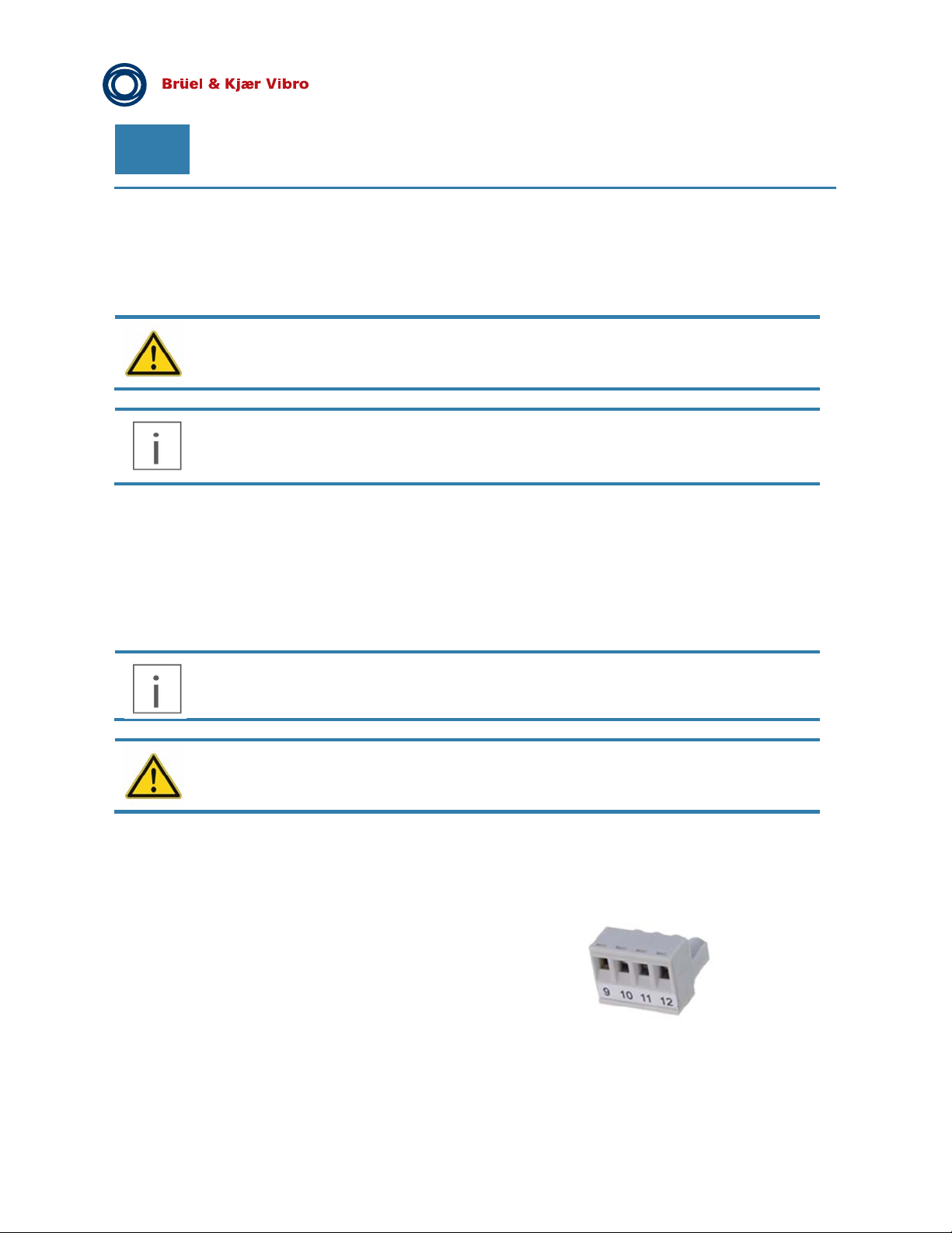
EN
Pre-Release
10 Mounting/installation of the VIBROCONTROL 18xx
Accident prevention
Improper opening of the product or removal of components, improper use, incorrect installation
or operation may result in personal injury or property damage.
If the VIBROCONTROL 18xx device is used in a manner not specified by the manufacturer,
the protection provided by the equipment may be impaired. The safety of any machine/system
incorporating the VIBROCONTROL 18xx device is the sole responsibility of the assembler of
the system
10.1 Assembly / disassembly of the device:
The VIBROCONTROL 18xx Vibration Monitor comes in a DIN rail enclosure ready to be clipped on a standard
DIN rail.
Before mounting, please note:
Provide sufficient air circulation above and below the unit.
To avoid fading of the text on the label, please try to keep the device out of direct sunlight.
The assembly may only be carried out in a de-energized state!
A metal clip at the rear of the enclosure is used to (un-)mount the device from/to the DIN- rail.
The device is mounted on a DIN rail by simply clicking on it.
10.2 Terminal marking
Each device is equipped with six numbered 4-pin
connections, i.e. equipped three on each side of
the case.
A label on the side of the VIBROCONTROL 18xx enclosure indicates the function of the terminals of the device.
The connection to the power supply and other interfaces is made via these terminals:
Page 72 of 84
Technical alterations reserved!
█
© Brüel & Kjaer Vibro ● July 2018 ● C106834.002 / V02
Page 73
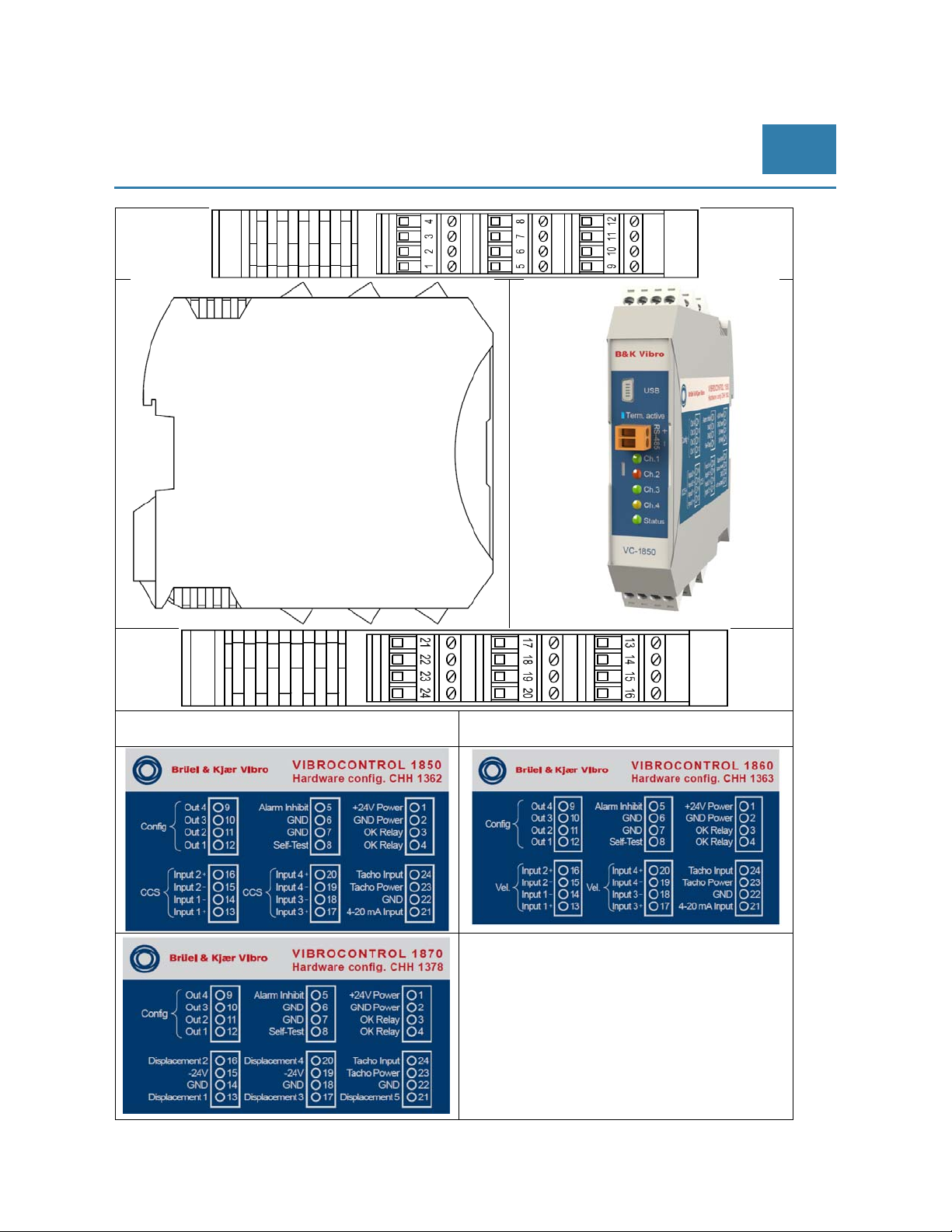
© Brüel & Kjaer Vibro │Instruction VC-1800 series
Mounting/installation of the
VIBROCONTROL 18xx
EN
© Brüel & Kjaer Vibro ● July 2018 ● C106834.002 / V02 ● █ Page 73 of 84
Technical alterations reserved!
Page 74
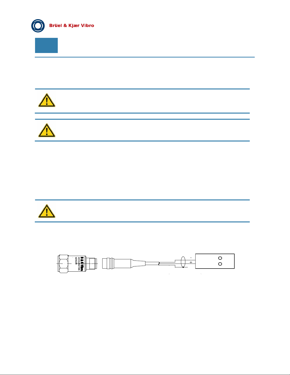
EN
10.3 Installation
Cables connected to the VC-18xx must be suitable for an ambient temperature
of -10 ° C to + 80 ° C.
External strain relief of the cables is recommended
The following order is recommended during installation:
Make the sensor connections
Make the relays and power outlets
Establish power supply
Pre-Release
10.3.1 Sensor connection
The shields of the incoming and outgoing cables must be laid on suitable equipotential
bonding.
CCS accelerometer (VIBROCONTROL 1850)
The acceleration sensors are connected to the terminals as 2-wire connections (plus and minus) (see sticker).
Up to 4 accelerometers can be connected to the VC-1850:
CSS
Schirm
Further sensor connections are:
16 (Input 2+) / 15 (Input 2-)
17 (Input 3+) / 18 (Input 3-)
20 (Input 4+) / 19 (Input 4-)
VIBROCONTROL 1850
Input 1- 14
Input 1+ 13
Page 74 of 84
Technical alterations reserved!
█
© Brüel & Kjaer Vibro ● July 2018 ● C106834.002 / V02
Page 75
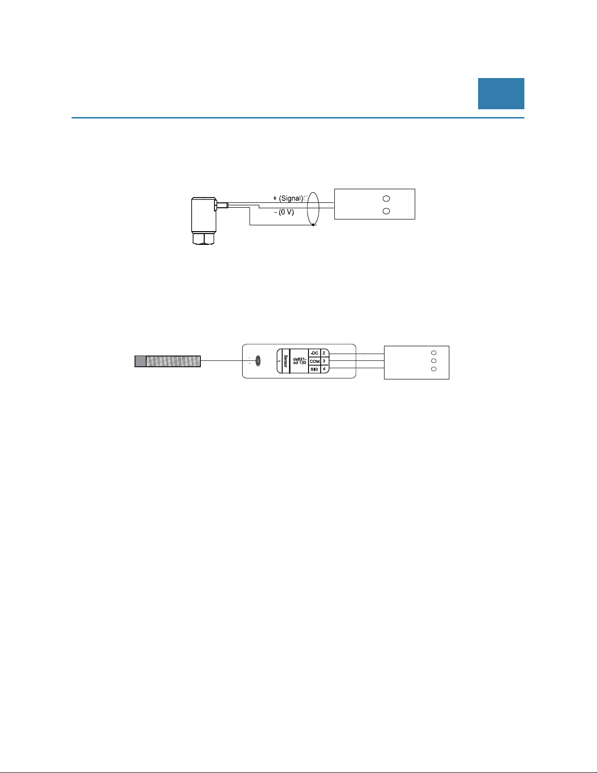
© Brüel & Kjaer Vibro │Instruction VC-1800 series
Mounting/installation of the
VIBROCONTROL 18xx
Velocity sensor (VIBROCONTROL 1860)
The acceleration sensors are connected as 2-wire connections (plus and minus) to terminals 16-20 (see
sticker). Up to 4 accelerometers can be connected to the VC-1850.
VIBROCONTROL 1860
EN
VS068
069
Further sensor connections are:
16 (Input 2+) / 15 (Input 2-)
17 (Input 3+) / 18 (Input 3-)
20 (Input 4+) / 19 (Input 4-)
Displacement sensor (VIBROCONTROL 1870)
Further sensor connections are:
16 (Displacement 2) / 15 (-24 V) / 14 (GND)
17 (Displacement 3) / 19 (-24 V) / 18 (GND)
20 (Displacement 4) / 19 (-24 V) / 18 (GND)
21 (Displacement 5) / 23 (-24 V) / 22 (GND)
Input 1+ 13
Input 1+ 14
Schirm
VIBROCONTROL 1870
-24 V 15
GND 14
Prox Input 1- 13
Tacho connections
The tacho connections are on the same terminals on all three VC-18xx units. The connection to the tacho
sensor is described in chapter 6.12 Speed sensor (tacho) input.
10.3.2 Analog outputs
The connections of the analog outputs are described in chapter 6.18 Configuration of the analog outputs.
10.3.3 Power Supply
Power supply of the power supply unit may only be carried out via disconnecting device (switch or
circuit breaker)!
© Brüel & Kjaer Vibro ● July 2018 ● C106834.002 / V02 ● █ Page 75 of 84
Technical alterations reserved!
Page 76
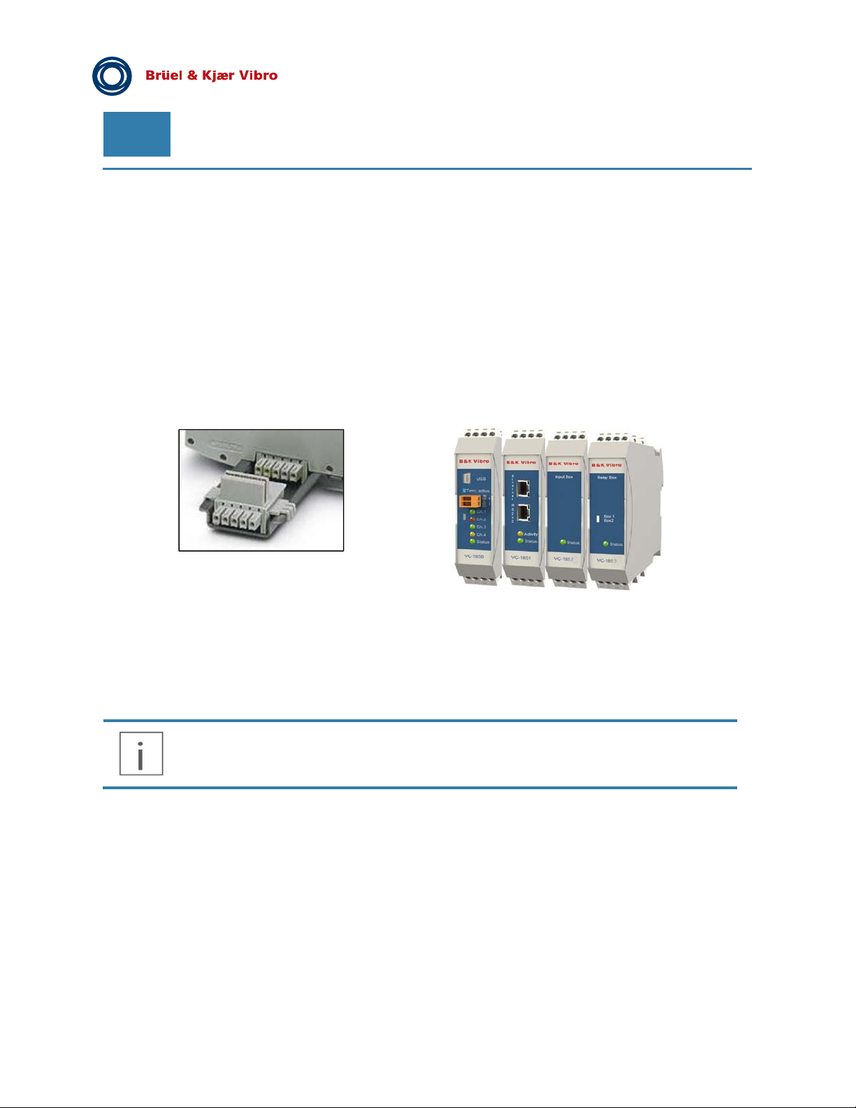
EN
Pre-Release
10.4 Powering and Start-up
After connecting to Power or changing setup the instruments is proceeding a startup program, which is
indicated by red, or blinking Channel LEDs and/or blinking OK LEDs. This procedure takes up to 30 seconds. In
case there is no violation of alert and danger levels or any OK failure, all LEDs should turn to green.
10.5 DIN-rail bus module connection
At the backside of the enclosure there is a 5-pin DIN-rail bus connector that can be used to pass common
power or certain signal(s) to adjacent module(s) that have the same type of DIN-rail enclosure like the VC1803/04, and/or other VIBROCONTROL 18xx Vibration Monitor(s). This could be main power, tacho signal,
RS-485 connection, etc.
The DIN-rail bus module is connected with spring contacts to five conductive pads at the rear edge of the
printed circuit board inside the VIBROCONTROL 18xx enclosure. The DIN-rail bus module can easily be
removed by gently pulling the DIN-rail bus module down in the direction of the length axis of the
VIBROCONTROL 18xx enclosure and can easily be remounted by carrying out the reverse action.
At the front of the enclosure there are two connectors marked “RS-485” and “USB” for connection to their
respective interfaces on a PLC, PC or VIBROCONTROL 1803.
The VIBROCONTROL 18xx device has no internal forced ventilation. This devices has no
external ventilation requirements as long as the surface temperature during operation does
not exceed the maximum ambient temperature value Ta stated elsewhere in this manual in
section 11: “Technical Data”
Page 76 of 84
Technical alterations reserved!
█ © Brüel & Kjaer Vibro ● July 2018 ● C106834.002 / V02
Page 77

© Brüel & Kjaer Vibro │Instruction VC-1800 series Technical data
11 Technical data
Input channels: Up to 4 dynamic vibration sensors:
VIBROCONTROL 1850: accelerometers (CCS),
VIBROCONTROL 1860: velocity sensors
1 Process input 4-20 mA, 0-20 mA or 0-22 V
1 Tacho input with NPN, PNP or AC
Sensor type: Accelerometer, 10-500 mV/g, type CCS :
Maximum input: ............................................................. ± 1.8 Vpk
Input overload: .............................................................. ± 1.8 Vpk
Sensor Bias Current:..................................................5 mA
Maximum voltage input: .............................................. -2 to -22 V
Peak detector, attack time: .......................................... 1-1000 ms
Peak detector, decay time: ............................................ 0.1-100 s
Band 1 (per input channel): Detectors: ................................................. rue RMS, Pk-Pk or Pk
Filter ranges: Velocity: ......................................... 0.7 to 1200 Hz
Acceleration: ....................................................... 0.7 Hz to 10 kHz
Displacement:. .......................................................... 7 to 1200 Hz
Measuring parameter: ......................... .mm/s, m/s2,μm,mm, mils
Selectable through user software Compact Setup
Band 2 (per input channel, CCS
only):
Standard measuring ranges: 10 or 20 or 50 or 100 mm/s, 2.5 or 6 or 12 or 24 m/s2
Standard frequency range: 10 Hz - 1000 Hz, -1 dB, 24 dB/oct.
Alarm detectors: Alert and Danger alarm per each detector with adjustable alarm
Detectors: True RMS, 2 Envelope detectors with user defined filters
from 1 - 500 Hz, Kurtosis and Crest Factor (top factor) according to
VDI 3832:
Filter ranges: Velocity: .......................................... 0.7 to 1200 Hz
Acceleration: ....................................................... 0.7 Hz to 10 kHz
Displacement: ........................................................ 0.7 to 1200 Hz
Measuring parameter: ......................... mm/s, m/s2,μm,mm, mils
Selectable through software Compact Setup
Other ranges are available through software Compact Setup
Optional: ............................................ 1-300, 1-1000, 0.7-10.5 Hz
High frequency band: ..................................................... 2-10 kHz
Non-linearity: 1.2% = 0.2 dB (typical, depending on type of filter)
More filter bands are available through software Compact Setup
limits. Alarm delay time:
Alert delay time .................................................................. 0-100 s
Danger delay time ............................................................. 0-100 s
Hang time for Alert and Danger .......................................... 0-100 s
Selectable through software Compact Commander
EN
© Brüel & Kjaer Vibro ● July 2018 ● C106834.002 / V02 ● █ Page 77 of 84
Technical alterations reserved!
Page 78
EN
Pre-Release
Process input Linear conversion of input signal at Process Input terminal.
Out of Range detection (Namur NE43 appliant)
Alert and Danger Low/High latchable speed alarms, each with a
user selectable alarm delay time (s) and an alarm relay
Total vibration alarm inhibitation if below or above certain RPM
value
Speed Sensor Input User selectable: NPN, PNP or 0-30 VAC Choice of display in RPS or
Configurable outputs: The user can configure up to 4 analog DC outputs or alarm relays in
OK relay: 1 redundant safety relay with break-function (power fail-safe).
Self-test: Can be activated digitally (by connecting ground (GND) to terminal
RPM
User selectable multiple pulses per revolution Maximum number of
pulses per second: 50000 Averaging time: 1-60 s
Total vibration alarm inhibitation if below or above certain RPM
value
Alert and Danger Low/High latchable speed alarms, each with a
user selectable alarm delay time (s) and an alarm relay
Conditional speed sensor error detector, which activates the
VIBROCONTROL 18xx system error relay
total.
DC outputs can be configured as 4-20 mA, 0-20 mA, 2-10 V or
0-10 V. Each output can be assigned to any of the measuring
parameters. Output is relative to measuring range.
Tolerance: .................................................................. max. ±0.3%
Voltage load: ............................................................... min. 10 kΩ
Current load: .............................................................. max. 400 Ω
Alarm Relays: Relays with break-function, can be user configured as
Alert or Danger relays with latch function or auto reset.
Type: .................................................... Open Drain (non isolated)
Max voltage: .......................................................................... 28 V
Max current:...................................................................... 100 mA
ON resistance: .................................................................... 12.9 Ω
Max OFF state leakage current: .......................................... 10 µA
If the power is cut, all relays will become activated, i.e. break, thus
FAIL SAFE.
Standby: MAKE mode; Triggered: BREAK mode.
All system failures, like cable short, cable break and internal system
failure, will automatically trip the safety relay.
Type: .......................................................... Mechanical (isolated)
Max voltage: .......................................................................... 28 V
Max current:...................................................................... 100 mA
Max insulation voltage ......................................................... 100 V
ON resistance: .................................................................... 12.9 Ω
Max OFF state leakage current: ......................................... 10 µA
#8 on the enclosure) or by PC using Compact Setup software.
Page 78 of 84
Technical alterations reserved!
█ © Brüel & Kjaer Vibro ● July 2018 ● C106834.002 / V02
Page 79
© Brüel & Kjaer Vibro │Instruction VC-1800 series Technical data
Alarm inhibit: Can be activated digitally (by connecting ground (GND) to terminal
#5 on the enclosure).
Alarm inhibit also works as an alarm reset that affects all Alert and
Danger alarms, but NOT System Failure alarms.
Alarm latch: Activated individually when configuring the Alert and danger alarm
setup(s) using the Compact Commander software.
Deactivated by short-time Alarm Inhibit.
Time waveform recording: Up to 4 input channels can record digital raw data (time waveform)
simultaneously to a PC running Compact Commander.
The recording can be done through:
RS-485/LAN (buffered) ............................................ Up to 10 kHz
Mini USB (real-time) ................................................. Up to 10 kHz
Time waveform recording can be either user or event activated.
Trending of measuring data: All input channels can be trended and alarms can be stored when
connected to either VIBROCONTROL 1803 Ethernet-Bridge or
directly to a PC running Compact Analyzer software. It’s also
possible to make an off- line FFT of recorded time stream signals.
Communication: RS-485 interface:
2 screw terminals on the front panel.
Daisy chain, up to 255 units.
Possibility to activate built-in 120 Ω termination resistor.
Speed up to 115.2 Kbaud (3 Mbaud over short distance).
USB interface:
Mini USB/B on the front panel.
Speed at 3 Mbaud.
Can be used for Direct contact to PC for configuration or post-
analysis of data with Compact Analyzer software.
LAN (option; requires VC-1803 Ethernet-Bridge):
Remote control by PC for configuration or post-analysis of
data with Compact Analyzer software
EN
Modularity: VIBROCONTROL 18xx Vibration Monitors can be interconnected to
Status LED’s:
adjacent VIBROCONTROL 1803/1804 Ethernet-Bridge as well as
VC-1801 Relay Modules by means of DIN rail bus connectors
5 light diodes indicate channel status (green, yellow, red) for each of
the 4 vibration input channels, as well as for general system status.
Channel LED’s 1 to 4:
Green ................................................................. Normal operation
Yellow .......................................................................... Alert alarm
Red ................................................... Danger alarm or cable error
System LED:
Green ................................................................. Normal operation
Green flash .............................................. Settling on all channels
Yellow flash ...................................................................... Self test
Red .............................................................................. Cable error
Red flash ...................................................... Critical system error
© Brüel & Kjaer Vibro ● July 2018 ● C106834.002 / V02 ● █ Page 79 of 84
Technical alterations reserved!
Page 80
EN
Pre-Release
Power supply: +24 V DC, ±5 %, max. power consumption; 10 W
Ambient temperature range In operation: .............................................. -10 °C ≤ Ta ≤ +50 °C
In storage: ................................................ -40 °C ≤ Ta ≤ +85 °C
Maximum relative humidity 95 % RH (non-condensing at +40 °C)
Pollution degree 2 (indoor use)
Maximum altitude 4000 m
Mounting Standard 35-mm DIN-rail
Temperature EN 60068-2-1:2007 Cold
EN 60068-2-2:2007 Dry heat
Operating: –10 to +50°C
Storage: –40 to +85°C
Maximum Humidity
Enclosure EN 60529 + A1:2002 ; Ingress Protection IP20 with screw terminals
EN 60068-2-78:2001 ; 95% RH (non-condensing at +40 °C)
Page 80 of 84
Technical alterations reserved!
█ © Brüel & Kjaer Vibro ● July 2018 ● C106834.002 / V02
Page 81
© Brüel & Kjaer Vibro │Instruction VC-1800 series Maintenance
EN
12 Maintenance
The VIBROCONTROL 18xx Vibration Monitor is in principle maintenance free.
12.1 Cleaning
The device can be cleaned on the outside with a slightly damp cloth.
Do not introduce moisture such as water or other liquids into the device!
If you experience a Red LED for one of the channels and a Red LED for “Status”, this means that the
connection between the vibration monitor and the sensor for that particular channel is disconnected. Please
check the integrity of the connection cable on both sides, i.e. at the side of the sensor and at input terminals on
the enclosure of the vibration monitor.
In the unlikely event that you experience erroneous behaviour of the device, e.g. a continuous Red flashing
„OK“ LED (System Failure), we advise you to carry out a complete self-test for a couple of minutes. In case the
system failure is still present after such a complete self-test we strongly recommend you to contact the
manufacturer for a repair of the device.
Whenever you contact the manufacturer for a repair of the device you are kindly requested to have the
following information at hand:
The type number of the vibration monitor: VIBROCONTROL 1850, VIBROCONTROL 1860.
The serial number of the device, visible on a label on the enclosure.
The colour of the status indicators in the Compact Commander Software that are active, if any. Indicators, that
show a malfunction, are usually coloured Red.
13 Disassembly and Disposal
Dismantling may only be carried out in the de-energized state!
The driver is subject to the Waste Disposal Act for Electrical and Electronic Equipment.
Do not dispose of the device in the regular household waste and observe local
waste disposal regulations.
You may also return the device to
64293 Darmstadt
WEEE Reg. No. DE 69572330
© Brüel & Kjaer Vibro ● July 2018 ● C106834.002 / V02 ●
Technical alterations reserved!
Brüel & Kjaer Vibro
Leydheckerstraße 10
Germany.
█
Page 81 of 84
Page 82
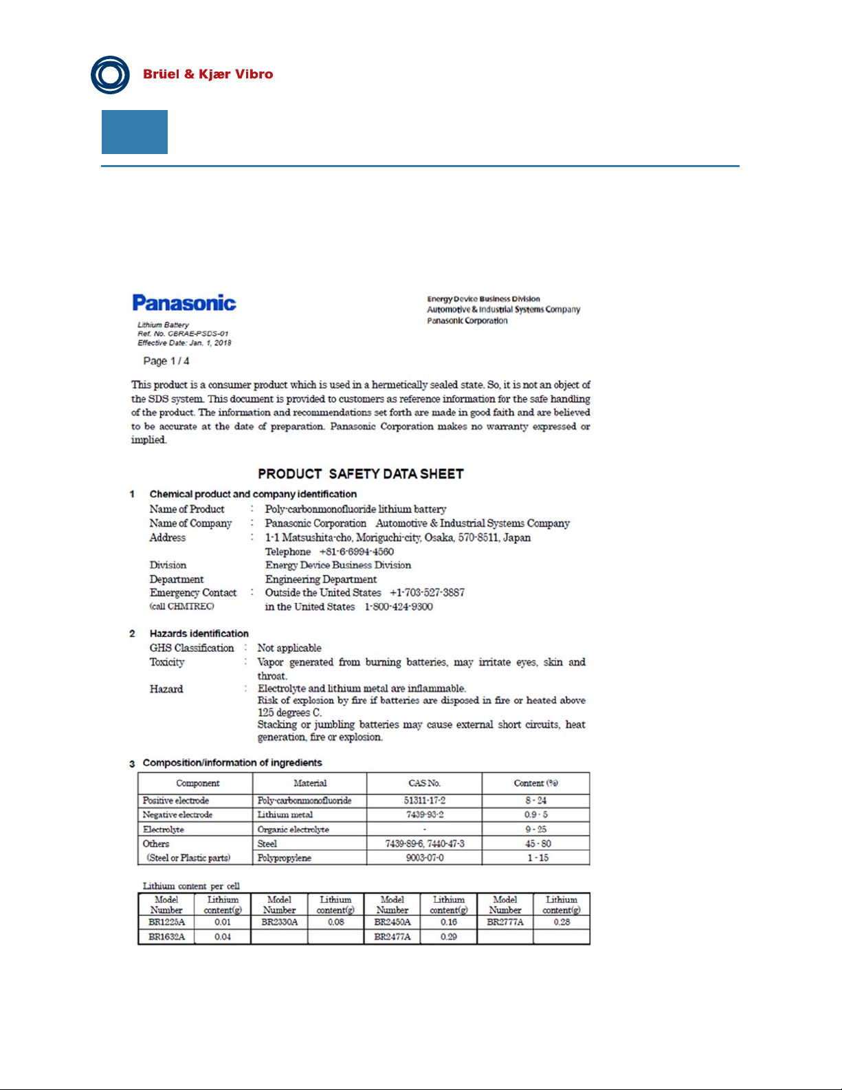
EN
Pre-Release
14 Appendix A: Backup Battery PSDS
The VIBROCONTROL 1804 includes RAM and contains a backup battery with this Product Safety Data Sheet:
Page 82 of 84
Technical alterations reserved!
█
© Brüel & Kjaer Vibro ● July 2018 ● C106834.002 / V02
Page 83

© Brüel & Kjaer Vibro │Instruction VC-1800 series Appendix A: Backup Battery PSDS
EN
© Brüel & Kjaer Vibro ● July 2018 ● C106834.002 / V02 ● █ Page 83 of 84
Technical alterations reserved!
Page 84

Contact
Brüel &Kjaer Vibro GmbH
Leydhecker Str.10
64293 Darmstadt
Germany
Phone: +49 6151 428 0
Fax: +49 6151 428 1000
VC-1800 series ● C106834.002 / V02 ● © Brüel & Kjaer Vibro ● Technical alterations reserved!
 Loading...