

Page 1
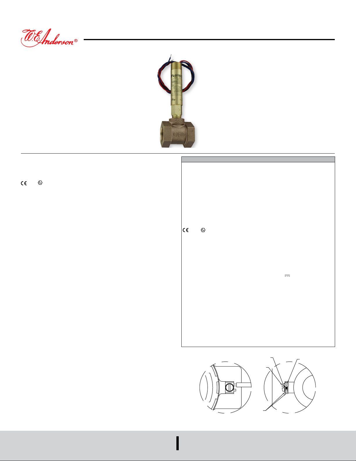
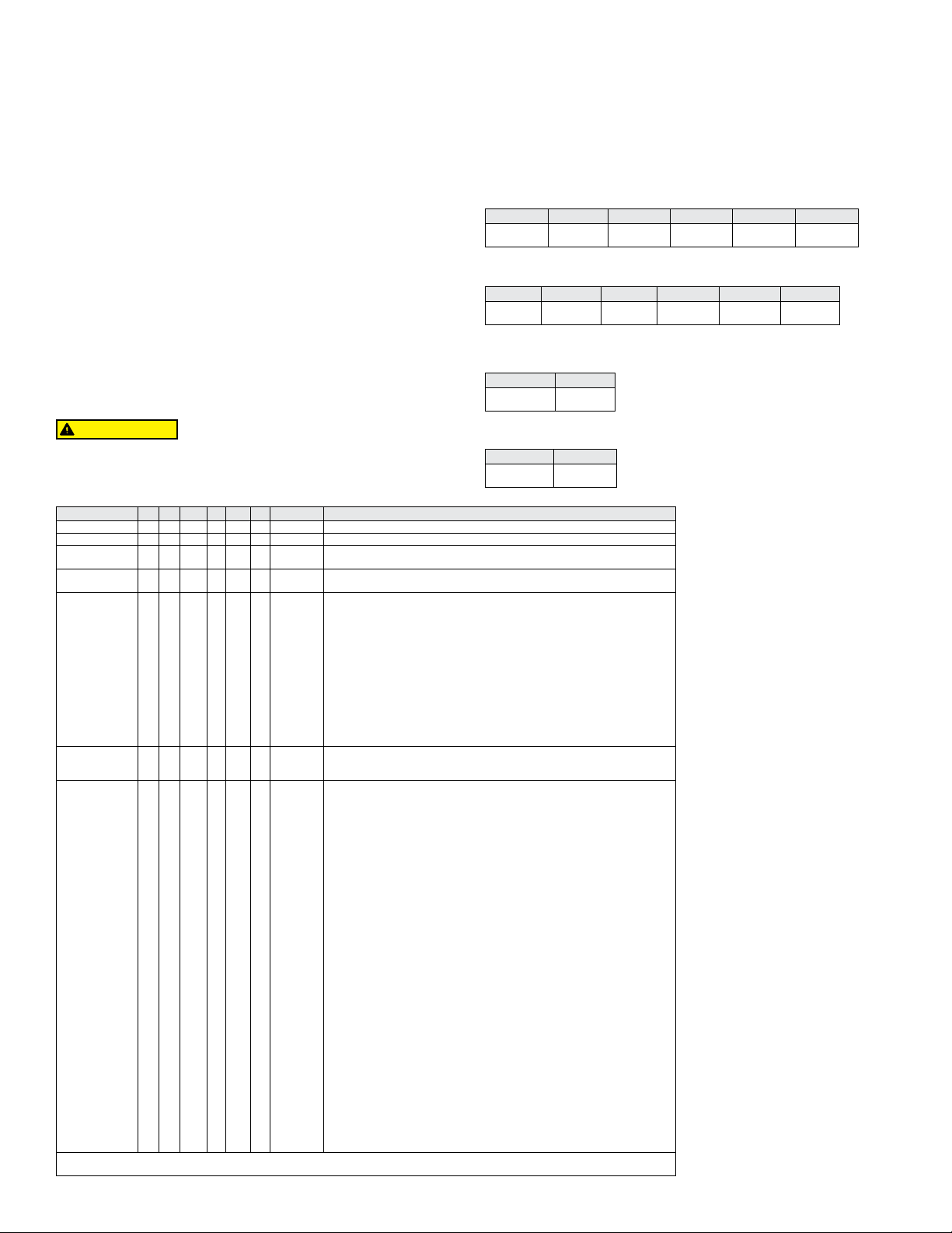
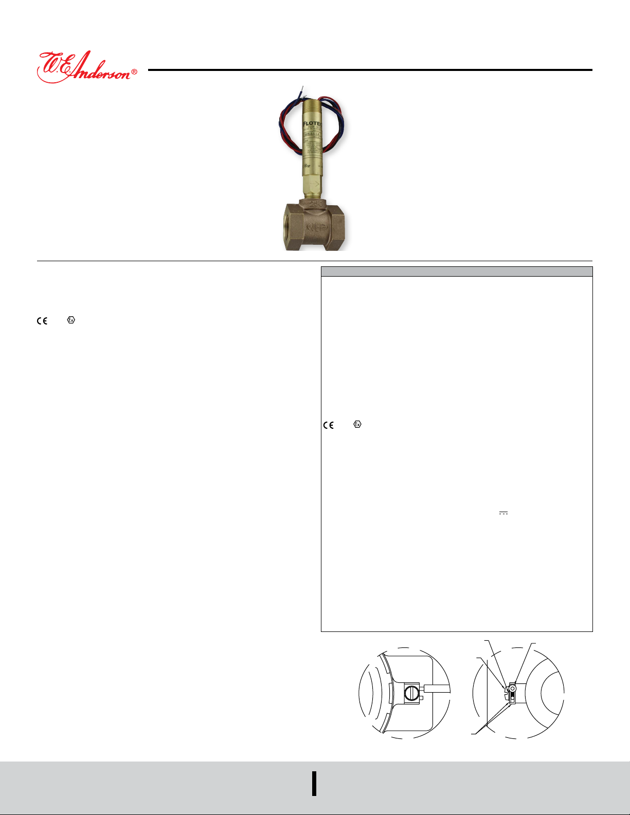
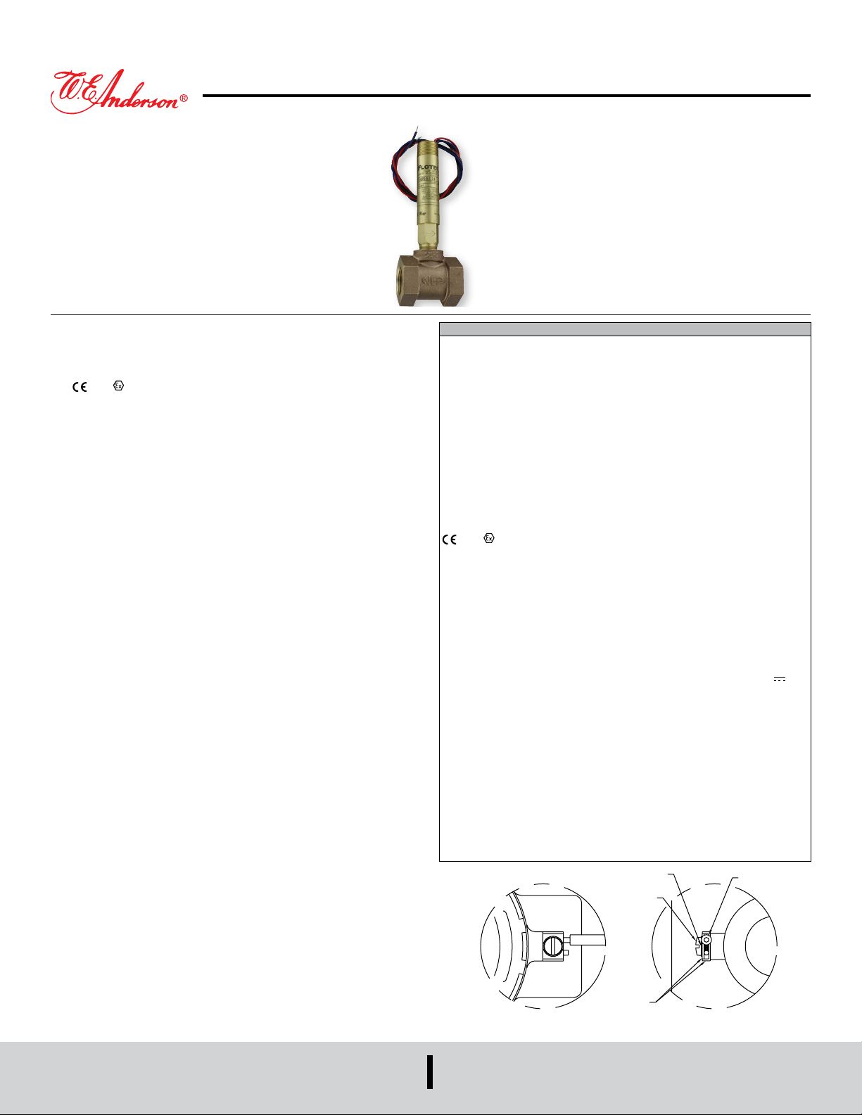
Series V6 Flotect® Flow Switch
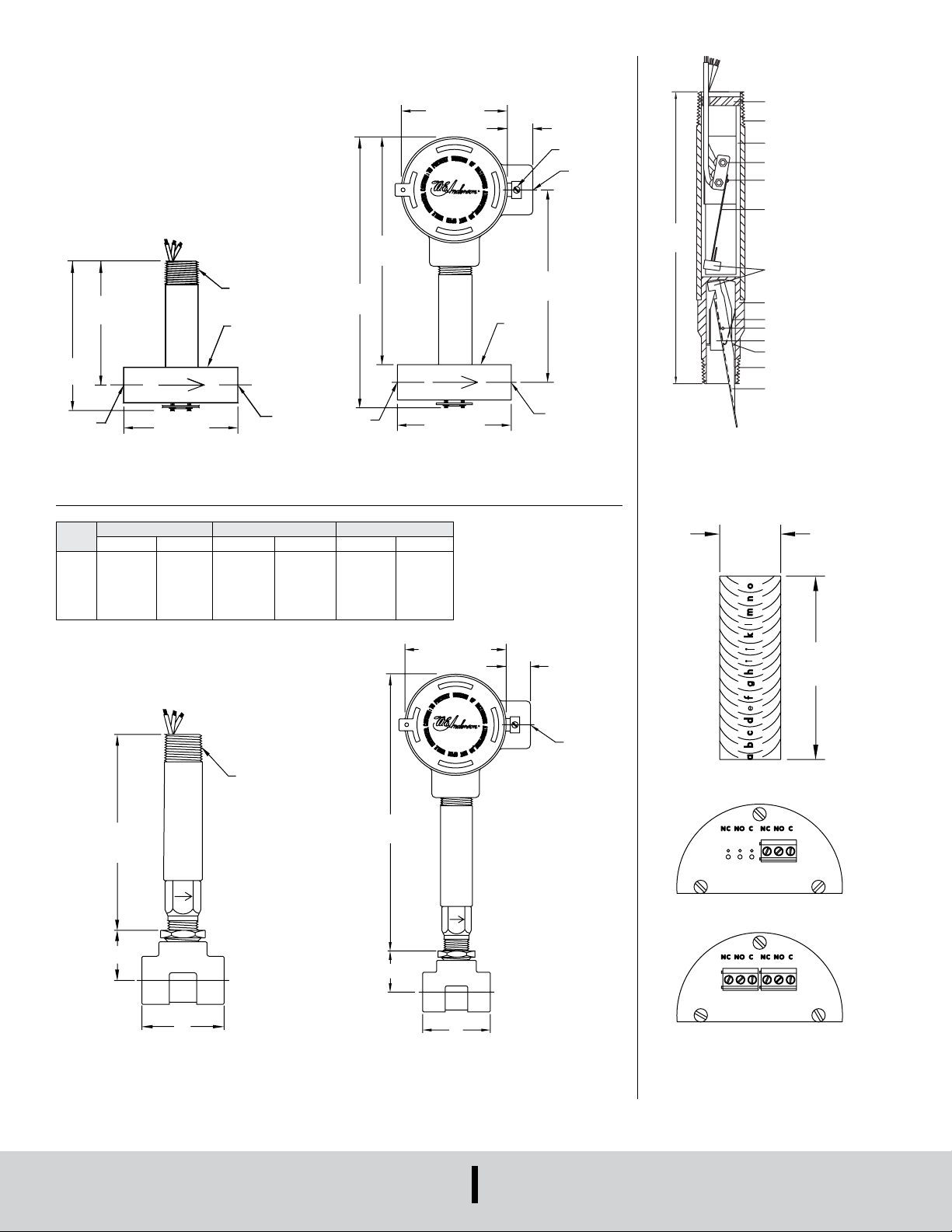
FRONT VIEW DETAIL SIDE VIEW DETAIL
LOCKWASHER
OR
Specications - Installation and Operating Instructions
Bulletin E-22
The Series V6 Flotect® Flow Switch is an inexpensive, explosion-proof ow switch
for use on air, water or other compatible gases and liquids. Three congurations are
available - 1. Factory installed in a tee. 2. With a trimmable vane for eld adjustment
and installation in a suitable tee. 3. Low ow models with an integral tee and adjustable
valve. All are available with an optional enclosure which is UL and CSA listed, or
Directive 2014/34/EU (ATEX) compliant for
2813 II 2 G Ex db IIC T6 Gb
Process Temp≤75°C or IECEx compliant for Ex db IIC T6 Gb Process Temp ≤ 75°C.
INSTALLATION
Unpack and remove any packing material found inside lower housing or tee.
Switch can be installed in any position but the actuation/deactuation ow rates in the
charts are based on horizontal pipe runs and are nominal values. For more precise
settings, units can be factory calibrated to specic ow rates.
V6 Models with Tee are supplied in 1/2˝ - 2˝ NPT sizes. Install in piping with arrow
pointing in direction of ow.
V6 Low Flow Models have 1/2˝ NPT connections and are eld adjustable. Install in
piping with arrow pointing in direction of ow. To adjust, loosen the four socket head
cap screws on bottom. The adjustment valve rotates 90° between “O” (open) and “C”
(closed). See ow charts for approximate ranges. Tighten screws once the required
ow rate has been set.
V6 with Field Trimmable Vane. These models enable the installer to choose
approximate actuation/deactuation points by trimming the full size vane at appropriate
letter-designated marks on a removable template. Flows are dened in the following
charts. Note that the charts are based on either brass or cast iron reducing tees or
stainless or forged steel straight tees with bushings where necessary. Install in piping
with arrow pointing in direction of ow.
When bushings are used, they must be back drilled to allow proper clearance for
unrestricted vane travel. Bore the I.D. to 13/16˝ (20 mm) on 1/2˝ x 3/4˝ bushings or 1˝
(25 mm) on larger bushings. The depth of the bore must leave internal threads 9/16˝
(14 mm) high for proper engagement between the lower housing of the switch and the
bushing. Check for proper vane travel and switch operation after installation.
ELECTRICAL CONNECTIONS
Connect wire leads in accordance with local electrical codes and switch action
required. N.O. contacts will close and N.C. contacts will open when ow increases
to the actuation point. They will return to “normal” condition when ow decreases to
the deactuation point. Black = Common, Blue = Normally Open and Red = Normally
Closed.
For units supplied with both internal ground and external bonding terminals, the
ground screw inside the housing must be used to ground the control. The external
bonding screw is for supplementary bonding when allowed or required by local code.
When external bonding conductor is required, conductor must be wrapped a minimum
of 180° about the external bonding screw. See below. Some CSA listed models are
furnished with a separate green ground wire. Such units must be equipped with a
junction box, not supplied but available on special order.
SPECIFICATIONS
Service: Gases or liquids compatible with wetted materials.
Wetted Materials: Standard V6 models: Vane: 301 SS; Lower body: Brass or 303
SS; Magnet: Ceramic; Other: 301, 302 SS; Tee: Brass, iron, forged steel, or 304 SS.
V6 low ow models: Lower body: Brass or 303 SS; Tee: Brass or 304 SS; Magnet:
Ceramic; O-ring: Buna-N standard, uoroelastomer optional; Other: 301, 302 SS.
Temperature Limits: -4 to 220°F (-20 to 105°C) Standard, MT high temperature
option 400°F (205°C) (MT not UL, CSA, ATEX, IECEx or KC) ATEX compliant AT,
IECEx IEC option and KC (KC option); Ambient temperature -4 to 167°F (-20 to
75°C); Process temperature: -4 to 220°F (-20 to 105°C).
Pressure Limit: Brass lower body with no tee models 1000 psig (69 bar), 303 SS
lower body with no tee models 2000 psig (138 bar). Brass tee models 250 psi (17.2
bar), iron tee models 1000 psi (69 bar), forged and SS tee models 2000 psi (138
bar), low ow models 1450 psi (100 bar).
Enclosure Rating: Weatherproof and explosion-proof. Listed with UL and CSA for
Class I, Groups A, B, C and D; Class II, Groups E, F, and G. (Group A on SS body
models only).
2813 II 2 G Ex db IIC T6 Gb Process Temp≤75°C Alternate Temperature
Class T5 Process Temp≤90°C, 115°C (T4) Process Temp ≤105°C consult factory.
EU-Type Certicate No.: KEMA 04ATEX2128.
ATEX Standards: EN 60079-0: 2011 + A11:2013; EN 60079-1: 2014.
IECEx Certied: For Ex db IIC T6 Gb Process Temp≤75°C Alternate Temperature
Class T5 Process Temp≤90°, 115°C (T4) Process Temp≤105°C consult factory.
IECEx Certicate of Conformity: IECEx DEK 11.0039; IECEx standards: IEC
60079-0: 2011; IEC 60079-1: 2014; Korean Certied (KC) for: Ex d IIC T6 Gb
Process Temp≤75°C; KTL Certicate Number: 12-KB4BO-0091.
Switch Type: SPDT snap switch standard, DPDT snap switch optional.
Electrical Rating: UL models: 5 A @125/250 VAC. CSA, ATEX and IECEx models:
5 A @ 125/250 VAC (V~); 5 A res., 3 A ind. @ 30 VDC (V ). MV option: 0.1 A @
125 VAC (V~). MT option: 5 A @125/250 VAC (V~). [MT option not UL, CSA, ATEX
or IECEx].
Electrical Connections: UL models: 18 AWG, 18˝ (460 mm) long. ATEX/CSA/
IECEx models: Terminal block.
Upper Body: Brass or 303 SS.
Conduit Connections: 3/4˝ male NPT standard, 3/4˝ female NPT on junction box
models. M25 x 1.5 with BSPT option.
Process Connection: 1/2˝ male NPT on models without a tee.
Mounting Orientation: Switch can be installed in any position but the actuation/
deactuation ow rates in the charts are based on horizontal pipe runs and are
nominal values.
Set Point Adjustment: Standard V6 models none. Without tee models vane is
trimmable. Low ow models are eld adjustable in the range shown. See set point
charts on opposite page.
Weight: 2 to 6 lb (.9 to 2.7 kg) depending on construction.
Options not Shown: Custom calibration, bushings, PVC tee, reinforced vane,
DPDT relays.
CONDUCT
SCREW
DWYER INSTRUMENTS, INC.
P.O. BOX 373 • MICHIGAN CITY, INDIANA 46360, U.S.A.
Phone: 219-879-8000
Fax: 219-872-9057
CLAMP
www.dwyer-inst.com
e-mail: [email protected]
Page 2
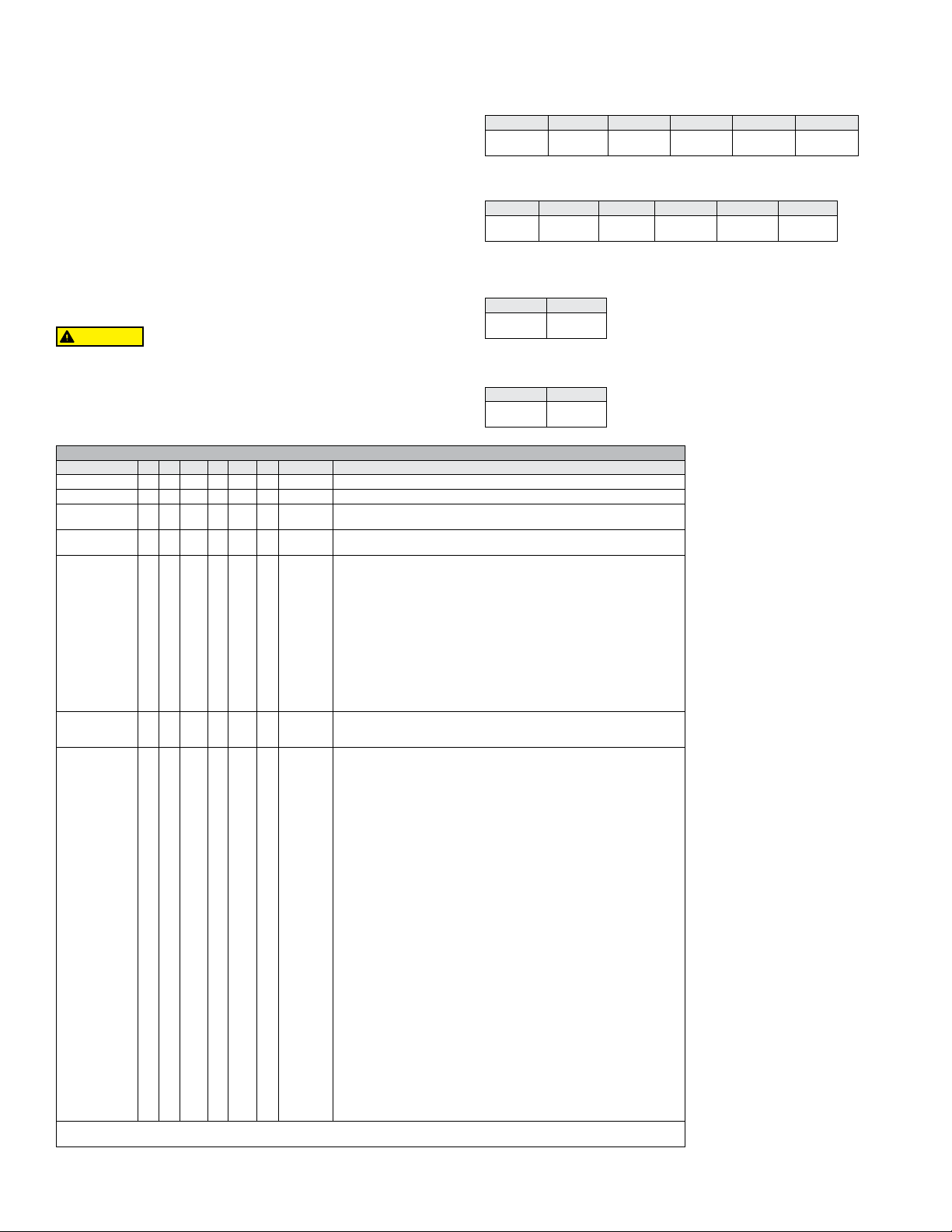
EU-Type Certicate, IECEx and KC Installation Instructions:
Cable Connection
The cable entry device shall be certied in type of explosion protection ameproof
enclosure “d”, suitable for conditions of use and correctly installed. For Ta ≥ 65°C cable
and cable gland rated ≥ 90°C shall be used.
Conduit Connection
An Ex d certied sealing device such as a conduit seal with setting compound shall be
provided immediately to the entrance of the valve housing. For Ta ≥ 65°C wiring and
setting compound, in the conduit seal, rated ≥ 90°C shall be used.
Note: ATEX, IECEx and KC units only: The temperature class is determined by
the maximum ambient and or process temperature. Units are intended to be used
in ambient of -20°C≤ Tamb ≤75°C. Units may be used in process temperatures up
to 105°C providing the enclosure and switch body temperature do not exceed 75°C.
The standard Temperature Class is T6 Process Temp ≤75°C. Alternate Temperature
Class of T5 Process Temp ≤90°C and 115°C (T4) Process Temp ≤105°C are available
consult factory.
Refer to Certicate No: IECEx DEK 11.0039 for conditions of safe use for
IECEx compliant units.
All wiring, conduit and enclosures must meet applicable codes for hazardous areas.
Conduits and enclosures must be properly sealed. For outdoor or other locations
where temperatures vary widely, precautions should be taken to prevent condensation
inside switch or enclosure. Electrical components must be kept dry at all times.
CAUTION
MAINTENANCE
Inspect and clean wetted parts at regular intervals. The cover should be in place at all
times to protect, the internal components from dirt, dust and weather and to maintain
hazardous location ratings. Disconnect device from the supply circuit before opening
to prevent ignition of hazardous atmosphere. Repairs to be conducted by Dwyer
Instruments, Inc. Units in need of repair should be returned to the factory prepaid.
To prevent ignition of hazardous atmospheres, disconnect the
device from the supply circuit before opening. Keep assembly
tightly closed when in use.
V6 With Tee
Cold Water - Factory Installed Tee
Approximate actuation/deactuation low Rates
GPM upper, M3/HR lower
1/2˝ NPT 3/4˝ NPT 1˝ NPT 1-1/4˝ NPT 1-1/2˝ NPT 2˝ NPT
1.5 1.0
0.34 0.23
Air-Factory Installed Tee
Approximate actuation/deactuation ow rates
SCFM upper, NM3/M lower
2.0 1.25
0.45 0.28
3.0 1.75
0.68 0.40
4.0 3.0
0.91 0.68
1/2˝ NPT 3/4˝ NPT 1˝ NPT 1-1/4˝ NPT 1-1/2˝ NPT 2˝ NPT
6.5 5.0
.18 .14
V6 Low Flow, Field Adjustable
Cold Water - Low Flow Models
Approximate actuation/deactuation ow rates
GPM upper, M3/HR lower
10.0 8.0
.28 .23
14 12
.40 .34
21 18
.59 .51
Minimum Maximum
.04 .03
.009 .007
Air - Low Flow Models
Approximate actuation/deactuation ow rates
SCFM upper, NM3/M lower
.75 0.60
0.17 0.14
Minimum Maximum
.18 .15
.005 .004
2.70 2.0
.08 .06
MODEL CHART
Example V6 EP -BB -D -1 -B -AT V6EPB-B-D-1-B-AT
Series V6 Flotect
®
mini-size ow switch
Construction EP Explosion proof
Body BB
Switch Type D
Tee
Connection
Size
Tee Type and
Material
Options 18
*Options that do no have ATEX or IECEx.
**BSPT options not compatible with KC option.
Attention: Units without the “AT” sufx are not Directive 2014/34/EU (ATEX) compliant. These units are not intended for use in potentially
hazardous atmospheres in the EU. These units may be CE marked for other Directives of the EU.
SS
S
1
2
3
4
5
6
LF
1E
2E
3E
4E
5E
6E
LFE
B
S
O
20
22
022A
31
AT
BUSH2
BUSH3
BUSH4
BUSH5
BUSH6
BUSH7
BUSH8
BUSH9
BUSH10
BUSH11
CSA
CV
FTR
GL
ID
IEC
JCTLH
KC
MT
MV
NN
ORFB
ORFS
PT
RV
ST
TBC
VIT
Brass
Stainless steel
DPDT
SPDT
1/2˝ NPT
3/4˝ NPT
1˝ NPT
1-1/4˝ NPT
1-1/2˝ NPT
2˝ NPT
Low ow with 1/2˝ NPT inlet and outlet
1/2˝ BSPT**
3/4˝ BSPT**
1˝ BSPT**
1-1/4˝ BSPT**
1-1/2˝ BSPT**
2˝ BSPT**
Low ow with 1/2˝ BSPT inlet and outlet**
Brass
Stainless steel
No tee with eld trimmable vane
0.018 spring for low ow
.020 spring for low ow
.022 spring for low ow
.022 spring for low ow with alnico magnet
.031 spring for low ow
ATEX approval
1/2˝ NPT x 3/4˝ NPT bushing
1/2˝ NPT x 1˝ NPT bushing
1/2˝ NPT x 1-1/4˝ NPT bushing
1/2˝ NPT x 1-1/2˝ NPT bushing
1/2˝ NPT x 2˝ NPT bushing
1/2˝ BSPT x 3/4˝ BSPT bushing, M25 X 1.5 conduit connection**
1/2˝ BSPT x 1˝ BSPT bushing, M25 X 1.5 conduit connection**
1/2˝ BSPT x 1-1/4˝ BSPT bushing, M25 X 1.5 conduit connection**
1/2˝ BSPT x 1-1/2˝ BSPT bushing, M25 X 1.5 conduit connection**
1/2˝ BSPT x 2˝ BSPT bushing, M25 X 1.5 conduit connection**
CSA*
Custom vane
Flow test report
Ground lead*
Custom nameplate
IECEx approval
Junction box with left side conduit
Korean certied
High temperature*
Gold contacts
No nameplate*
Brass orice
Stainless steel orice
Paper tag
Reinforced vane
Stainless steel tag
Terminal lock connector*
Flouroelstomer seals
6.0 5.0
1.36 1.14
33 30
.93 .85
10.0 8.5
2.27 1.93
43 36
1.19 1.02
Page 3

V6 With Field Trimmable Vane
Cold Water - Brass or Cast Iron Reducing Tee
Approximate actuation/deactuation ow rates
GPM upper, M3/HR lower
Air - Brass or Cast Iron Reducing Tee
Approximate actuation/deactuation ow rates
SCFM upper, NM
3
/M lower
Vane 1/2˝ NPT 3/4˝ NPT 1˝ NPT 1-1/4˝ NPT 1-1/2˝ NPT 2˝ NPT
Full Size 9.0 8.5
a 9.5 9.0
b 10.0 9.3
c 11.0 10.0
d 6.2 5.5
e 7.0 6.5
f 4.3 3.9
g 4.9 4.4
h 5.5 5.0
i 3.5 3.1
j 4.0 3.5
k 4.6 4.2
l 2.6 2.3
m 1.6 1.3
n 2.2 1.8
o 3.0 2.4
0.4 0.3
0.5 0.4
0.7 0.5
0.6 0.5
3.5 3.1
0.8 0.7
4.3 3.8
1.0 0.9
0.8 0.7
0.9 0.8
1.04 0.95
5.6 5.2
1.3 1.2
6.3 6.1
1.43 1.39
8.0 7.5
1.8 1.7
1.0 0.9
1.1 1.0
1.2 1.1
6.0 5.6
1.4 1.3
7.0 6.6
1.6 1.5
8.0 7.6
1.8 1.7
10.0 9.0
2.3 2.0
12.0 10.0
2.7 2.3
1.4 1.2
1.6 1.5
7.6 7.1
1.7 1.6
8.0 7.3
1.8 1.7
9.0 8.2
2.0 1.9
10.0 9.0
2.3 2.0
13.0 11.0
3.0 2.5
15.0 13.0
3.4 3.0
2.0 1.9
2.2 2.0
2.3 2.1
2.5 2.3
12.0 10.0
2.7 2.3
13.0 11.0
3.0 2.5
14.0 12.0
3.2 2.7
Vane 1/2˝ NPT 3/4˝ NPT 1˝ NPT 1-1/4˝ NPT 1-1/2˝ NPT 2˝ NPT
Full Size 39.0 37.0
a 40.0 38.0
b 42.0 40.0
c 50.0 44.0
d 27.0 25.0
e 30.0 28.0
f 20.0 18.0
g 21.0 19.0
h 23.0 21.0
i 16.0 15.0
j 18.0 16.0
k 19.0 17.0
l 13.0 12.0
m 6.4 3.8
n 10.0 7.0
o 12.0 9.0
0.18 0.11
0.28 0.20
0.34 0.25
0.37 0.34
15.0 14.0
0.42 0.40
20.0 16.0
0.57 0.45
0.45 0.42
0.51 0.45
0.54 0.48
22.0 20.0
0.62 0.57
25.0 23.0
0.71 0.65
32.0 28.0
0.91 0.79
0.57 0.51
0.59 0.54
0.65 0.59
24.0 22.0
0.68 0.62
28.0 25.0
0.79 0.71
33.0 30.0
0.93 0.85
38.0 35.0
1.08 0.99
45.0 42.0
1.27 1.19
0.76 0.71
0.85 0.79
32.0 30.0
0.85 0.79
32.0 30.0
0.91 0.85
34.0 32.0
0.96 0.91
37.0 34.0
1.05 0.96
39.0 36.0
1.10 1.02
51.0 45.0
1.44 1.27
69.0 57.0
1.95 1.61
1.10 1.05
1.13 1.08
1.19 1.13
1.42 1.25
55.0 46.0
1.56 1.30
Cold Water - Stainless or Forged Steel Straight Tee and Bushing
Approximate actuation/deactuation ow rates
GPM upper, M
3
/HR lower
Vane 1/2˝ NPT 3/4˝ NPT 1˝ NPT 1-1/4˝ NPT 1-1/2˝ NPT 2˝ NPT
Full Size 5.0 4.5
a 5.5 5.0
b 6.2 5.7
c 6.8 6.3
d 2.8 2.4
e 3.4 3.0
f 4.0 3.6
g 2.0 1.5
h 2.5 2.0
i 3.5 3.0
j 7.0 5.5
k 10.0 8.0
0.5 0.3
0.6 0.5
0.8 0.7
1.6 1.2
2.3 1.8
0.6 0.5
0.8 0.7
0.91 0.82
5.0 3.6
1.1 1.0
6.5 6.1
1.48 1.39
9.0 8.2
2.0 1.9
1.1 1.0
1.2 1.1
1.4 1.3
1.5 1.4
8.5 7.8
1.9 1.8
10.0 9.2
2.3 2.1
12.0 10.0
2.7 2.3
8.5 7.8
1.9 1.8
9.2 8.6
2.1 2.0
9.8 9.0
2.2 2.0
12.0 10.0
2.7 2.3
13.0 11.0
3.0 2.5
Air - Stainless or Forged Steel Straight Tee and Bushing
Approximate actuation/deactuation ow rates
SCFM upper, NM3/M lower
Vane 1/2˝ NPT 3/4˝ NPT 1˝ NPT 1-1/4˝ NPT 1-1/2˝ NPT 2˝ NPT
Full Size 21.0 18.0
a 22.0 20.0
b 24.0 22.0
c 28.0 26.0
d 12.0 10.0
e 14.0 12.0
f 16.0 14.0
g 8.0 6.5
h 11.0 10.0
i 14.0 13.0
j 27.0 24.0
k 39.0 36.0
0.23 0.18
0.31 0.28
0.40 0.37
0.76 0.68
1.10 1.02
0.34 0.28
0.40 0.34
0.45 0.40
19.0 17.0
0.54 0.48
26.0 24.0
0.74 0.68
32.0 30.0
0.91 0.85
0.59 0.51
0.62 0.57
0.68 0.62
0.79 0.74
33.0 30.0
0.93 0.85
37.0 34.0
1.05 0.96
43.0 40.0
1.22 1.13
33.0 30.0
0.93 0.85
39.0 36.0
1.10 1.02
42.0 38.0
1.19 1.08
51.0 46.0
1.44 1.30
55.0 50.0
1.56 1.42
Page 4
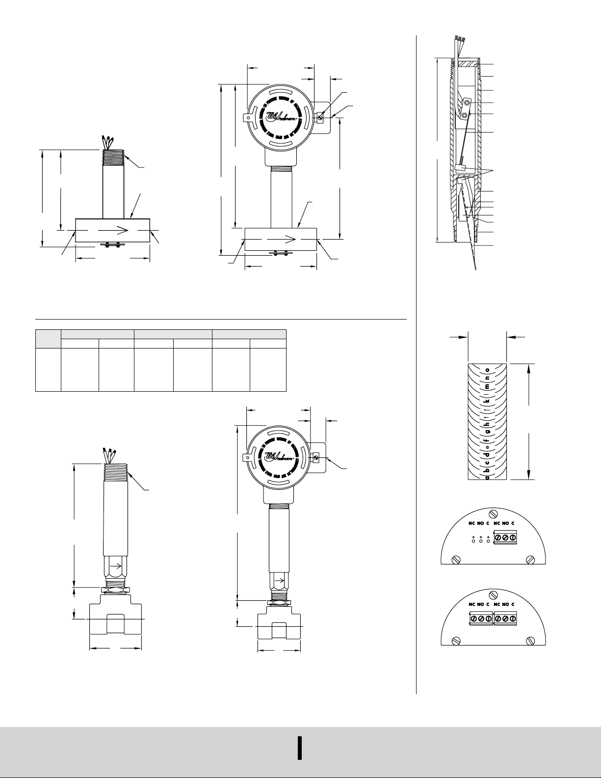
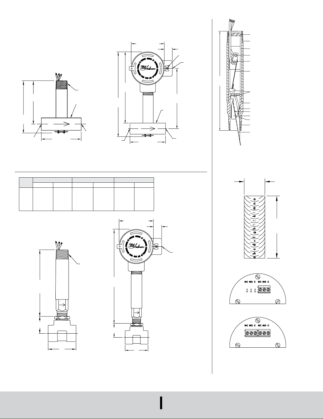
DIMENSIONS
3/4˝ NPT
[136.5]
"A"
3-3/8 [85.72] DIA.
T
[235.0]
"A"
3-3/8 [85.72] DIA.
1/2˝ FEMALE NPT
GROUND
[1
NPT
1/2˝ FEMALE
.625
[47.62]
5-13/16
[147.69]
LOWER HOUSING-BRASS
DPDT
Series V6 Flotect
3-15/16
[100.0]
4-1/2
14.3]
INLET
1/2˝ FEMALE
®
Flow Switch
3-5/8 [92.07]
V6 low ow
3/4˝ NPT
1-1/8 SQ.
[28.57]
OUTLET
NPT
13/16 [20.63]
EXTERNAL
3/4˝ FEMALE NPT
7.250
[184.2]
6-1/8
1-1/8 SQ.
[28.57]
[155.5]
OUTLET
1/2˝ FEMALE
NPT
8-5/8
[219.1]
INLET
V6 low ow with CSA, IECEx, ATEX conduit enclosure
3-5/8 [92.07]
LOCKING COLLAR
ASSEMBLY
3/4 NPT
UPPER HOUSING
SWITCH SUPPORTS
SPDT (OR DPDT)
SNAP SWITCH
MAGNET LEVER PIN
MAGNET LEVER
ASSEMBLY
MAGNETS
OR STAINLESS STEEL
VANE SPRING
VANE PIVOT PIN
VANE PIVOT BRACKET
SNAP RING
1/2 NPT
STAINLESS
STEEL VANE
OVERALL LENGTH WITH
1-1/4˝ TEE CONNECTION
APPROXIMATELY 8˝
V6 with eld
trimmable vane
Brass/Ductile Iron Forged/Stainless Steel Malleable Iron
Pipe
Size
Dim. A Dim. B Dim. A Dim. B Dim. A Dim. B
1/2˝
2-1/4 [57]
3/4˝
2-3/8 [60]
1˝
2-1/2 [64]
1-1/4˝
2-5/8 [67]
1-1/2˝
2-7/8 [73]
2˝
3 [76]
1-1/8 [29]
1-1/4 [32]
1-3/8 [35]
1-1/2 [38]
1-5/8 [41]
1-7/8 [48]
5-3/8
"B"
V6 with tee
2-1/4 [57]
2-5/8 [67]
3 [76]
3-1/2 [89]
4 [102]
4-3/4 [121]
1-1/8 [29]
1-7/8 [47]
2-1/8 [54]
2-1/2 [64]
2-3/4 [70]
3-1/8 [79]
2-1/2 [64]
2-5/8 [67]
2-7/8 [73]
3 [76]
3-1/4 [83]
3-1/2 [89]
1-1/4 [32]
1-3/8 [35]
1-1/2 [38]
1-3/4 [44]
1-7/8 [48]
2-1/8 [54]
9-1/4
"B"
V6 with tee and CSA, IECEx, ATEX
conduit enclosure
13/16 [20.63]
3/4 FEMALE NP
[15.87]
1.875
Trimmable vane
SPDT
Terminal connections
CSA, IECEx, ATEX enclosures
DWYER INSTRUMENTS, INC.
P.O. BOX 373 • MICHIGAN CITY, INDIANA 46360, U.S.A.
Phone: 219-879-8000
Fax: 219-872-9057
www.dwyer-inst.com
e-mail: [email protected]
Page 5
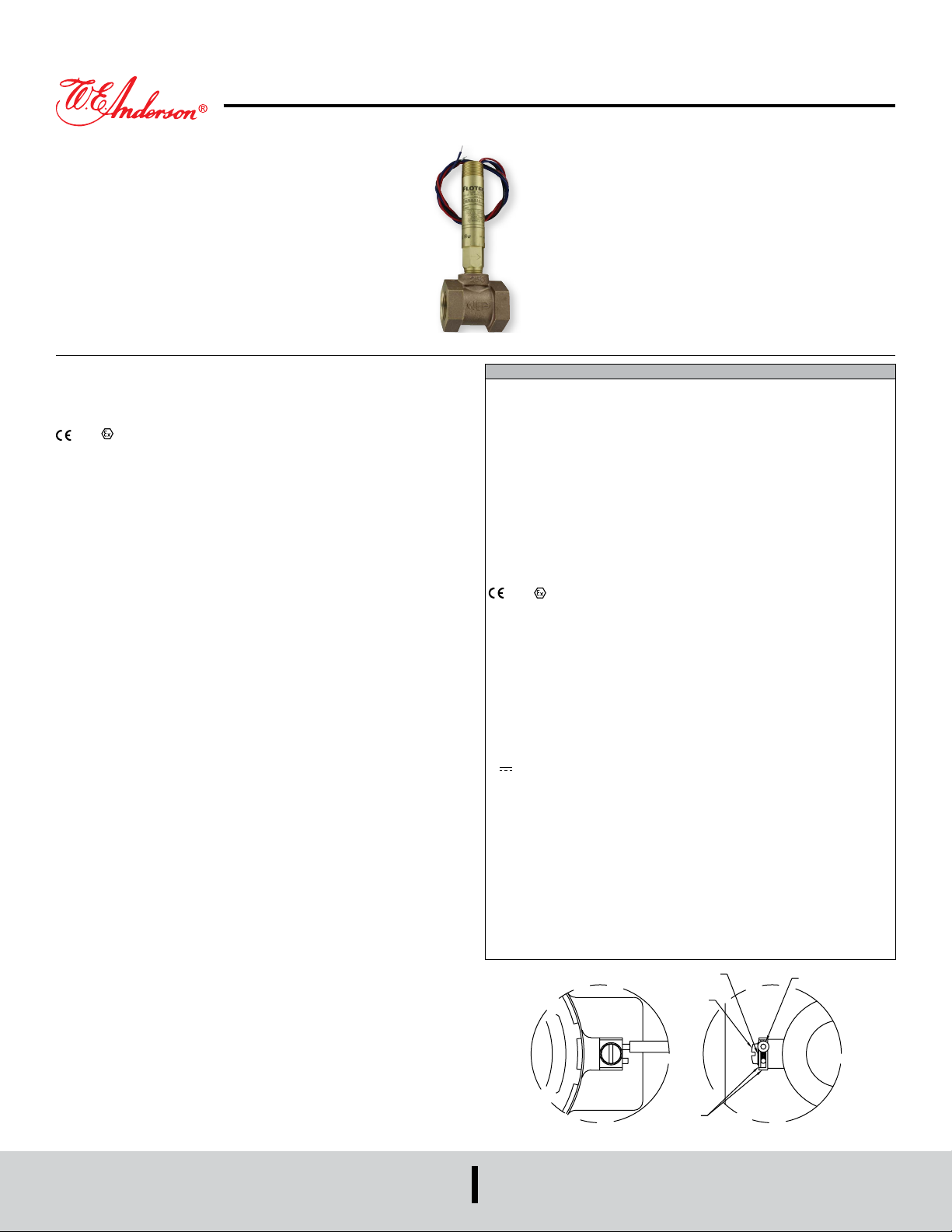
Flussostat FLOTECT® Série V6
VUE DE FACE DÉTAILLÉE VUE DE CÔTÉ DÉTAILLÉE
PINCE
CONDUCTEUR
Specications - Installation and Operating Instructions
Bulletin E-22
le ussostat Flotect® série V6 est un ussostat antidéagration économique qui
s’utilise avec l’air, l’eau ou autres gaz et liquides compatibles. Trois congurations
sont disponibles - 1. en té installé en usine. 2. avec une palette éboutable pour le
réglage du champ et installation dans un té adapté. 3. modèles faible débit avec un té
intégré et valve réglable. Tous les modèles sont disponibles avec un boitier optionnel
listé dans les normes UL et CSA ou conforment à la Directive 2014/34/EU (ATEX) pour
2813 II 2 G Ex db IIC T6 Gb
Temp. de fonctionnement ≤75°C ou conforment à la norme IECEx pour Ex db IIC T6
Gb Temp. de fonctionnement ≤ 75°C.
INSTALLATION
Déballer et retirer tout emballage se trouvant à l’intérieur du corps inférieur ou du té.
Le ussostat peut être installé dans n’importe quelle position mais les débits
d’activation/désactivation indiqués sur les tableaux sont basées sur une position
horizontale du tuyau et sont des valeurs nominales. Pour une installation plus précise,
les unités peuvent être calibrées en usine à des débits spéciques.
Les modèles V6 avec té sont fournis en 1/2˝ - 2˝ NPT. Installer dans le tuyaux avec la
èche pointant dans la direction du débit.
Les modèles V6 faible débit sont équipés de raccords 1/2˝ NPT et leur champ est
réglable. Installer dans le tuyaux avec la èche pointant dans la direction du débit.
Pour régler, dévisser les quatre vis à tête cylindrique situées en bas. Les valves de
réglage tournent à 90° entre « O » (ouvert) et « F » (fermé). Voir les tableaux de
débit pour les plages approximatives. Resserrer les vis une fois que le débit désiré
a été réglé.
V6 avec palette graduée éboutable. Ces modèles permettent à l’installateur de
choisir les points d’activation/désactivation en coupant la palette au niveau voulu,
marqué d’une lettre sur un gabarit amovible. Les débits sont dénis dans les tableaux
suivants. Les données des tableaux sont basées soit sur des tés réducteurs en laiton
ou en acier inox, soit sur des tés droits en acier inox ou forgé, avec bagues quand
nécessaire. Installer dans le tuyaux avec la èche pointant dans la direction du débit.
Quand l’emploi de bagues est nécessaire, il faut qu’elles soient percées an de
permettre le passage sans accrochage de la palette. Aléser jusqu’à obtenir un
diamètre intérieur de 20 mm pour les bagues de 1/2˝ x 3/4˝ ou un diamètre interne de
25 mm pour les bagues plus grandes. L’épaisseur de l’alésage doit laisser un letage
interne de 14 mm de hauteur an de permettre le passage entre l’emplacement
inférieur du dispositif et la bague. Vérier que la palette passe sans accrochage et que
le ussostat fonctionne correctement après installation.
RACCORDEMENTS ÉLECTRIQUES
Connecter les câbles électriques en suivant les codes électriques locaux et activer
l’action requise. Les contacts N.O ferment et les contacts N.F. s’ouvrent quand le débit
augmente jusqu’à son point d’intervention. Ils retourne à un statut « normale » quand
le débit baisse jusqu’au point de désactivation. Noir = commun, Bleu =
normalement ouvert et Rouge = normalement fermé.
Pour les unités fournies avec, à la fois, des bornes de terre internes et des bornes
de raccordement externes, la vis de terre, située dans le boîtier, doit être utilisée
pour relier le contrôle à la terre. La borne à vis externe permet un raccordement
supplémentaire quand cela est possible ou quand cela est exigé par le code local.
Quand un conducteur d’équipotentialité est requis, le conducteur doit être enroulé à
180° autour de la borne à vis externe. Voir ci-dessous. Quelques uns des modèles
homologués par le CSA sont fournis avec un câble de terre séparé.
Ces unités doivent être équipées d’un boîtier de jonction, qui n’est pas fourni mais
peut être commandé.
SPÉCIFICATIONS
Utilisation: Gaz ou liquides compatibles avec les matériaux mouillés.
Matériaux mouillés: modèles V6 standards: palette: inox 301, corps inférieur:
laiton ou inox 303, aimant: céramique, autres: inox 301, 302, té : laiton, fer, acier
forgé ou inox 304. Modèles V6 faible débit : partie inférieure : laiton ou inox 303;
té: laiton ou inox 304; aimant: laiton ou inox 303; aimant: céramique; joint torique:
buna-N standard, uoroélastomère optionnel; autres: acier inox 301, 302.
Températures limites: de -20 à 105° C (-4 à 220° F) en standard, Option MT haute
température à 205° C (400° F) (MT non homologuée UL, CSA, ATEX, IECEx ou
KC) AT conforme à la directive ATEX et options IECEx de la CEI et KC (option KC),
température ambiante de -20 à 75° C (-4 à 167° F), température de fonctionnement
: de -20 à 105° C (-4 à 220° F).
Pression limite: Modèles avec corps inférieur en laiton sans té 1000 psig (69
bar), modèles avec corps inférieur en acier inox 303 sans té 2000 psig (138 bar).
modèles avec té en laiton 250 psi (17.2 bar), modèles avec té en fer 1000 psi
(69 bar), modèles avec té en acier forgé et inoxydable 2000 psi (138 bar), modèles
à faible débit 1450 psi (100 bar).
Indice de protection: étanche et antidéagrant. Normes UL et CSA : classe I,
groupes A, B, C et D ; classe II, groupes E, F et G (groupe A pour les modèles avec
corps en acier inoxydable uniquement).
2813 II 2 G Ex db IIC T6 Gb Température de fonctionnement ≤75°C
température intermédiaire classe T5 Temp. de fonctionnement ≤90°C, 115°C
(T4) Temp. de fonctionnement ≤105°C consulter l’usine. Certicat CE n° : KEMA
04ATEX2128.
Normes ATEX: EN60079-0:2012 +A11: 2013; EN60079-1: 2014.
Certié IECEx: pour Ex db IIC T6 Gb Température de fonctionnement ≤75°C
température intermédiaire classe T5 Temp. de fonctionnement ≤90°C, 115°C (T4)
Temp. de fonctionnement ≤105°C consulter l’usine.
Certicat de conformité IECEx: IECEx DEK 11.0039; Normes IECEx: IEC
60079-0: 2011; IEC 60079-1: 2014; Certication coréenne (KC) pour: Ex d IIC T6
Gb Température de fonctionnement ≤75° C (167° F); Numéro de certicat KTL:
12-KB4BO-0091.
Type d’interrupteur électrique: interrupteur à action rapide SPDT en standard,
interrupteur à action rapide en option.
Caractéristiques électriques: modèles UL: 5A @125/250 Vca. Modèles CSA,
ATEX et IECEx: 5A @ 125/250 Vca (V~); 5A résistif., 3A inductif. @ 30 VDC
(V ). Option MV: .1A @ 125 Vca (V~). Option MT : 5A @125/250 Vca (V~).
(Option MT non homologuée UL, CSA, ATEX ou IECEx).
Raccordements électriques: modèles UL: 1 mm2, 460 mm. Modèles CSA, ATEX
et IECEx: bornier.
Partie supérieure: Laiton ou acier inox 303.
Conduit Connections: mâle NPT 3/4˝ standard, femelle NPT 3/4˝ sur les modèles
boitier de jonction ou M25 x 1,5 avec BSPT en option.
Type de raccord: mâle NPT 1/2˝ sur modèles sans té.
Orientation de montage: Le ussostat peut être installé dans n’importe quelle
position mais les débits d’activation/désactivation indiqués sur les tableaux sont
basés sur une position horizontale du tuyau et sont des valeurs nominales.
Réglage de l’index de consigne: Aucun pour les modèles V6 standard. Sauf pour
les modèles avec té, la palette peut être éboutée. Le champ des modèles à faible
débit peut être réglé à l’intérieur de la plage indiquée. Voir tableaux de l’index de
consigne sur la page ci-contre.
Poids: de 9 à 2.7 kg selon le type de fabrication.
Options non indiquées: calibration personnalisée, bagues, té en PVC, palette
renforcée, relais DPDT.
VIS
DWYER INSTRUMENTS, INC.
P.O. BOX 373 • MICHIGAN CITY, INDIANA 46360, U.S.A.
RONDELLE
Téléphone: 219-879-8000
Fax: 219-872-9057
www.dwyer-inst.com
e-mail: [email protected]
Page 6
Instructions d’installation conformes aux exigences du certicat type CE, IECEx
et KC:
Branchement des câbles
Le dispositif d’entrée du câble doit être équipé d’un boîtier de protection certié type
« d » en ce qui concerne la protection contre les explosions et les ammes.
Il doit être adapté aux conditions d’utilisation et installé correctement. Utiliser un câble
et un passe-câbles de cote ≥ 90°C pour une Ta ≥ 65°C.
Raccord des conduits
Un dispositif de scellement certié Ex d, comme par exemple un joint avec composé
durcissable, doit immédiatement être posé à l’entrée de l’emplacement de la palette.
Pour une Ta ≥ 65°C, à l’intérieur du dispositif de scellement, utiliser un câblage et un
composé durcissable de cote ≥ 90°C.
Remarque: unités ATEX, IECEx et KC uniquement: la classe de température
est déterminée par la température maximale ambiante ou par la température de
fonctionnement. Les unités sont conçues pour être utilisées à des températures
ambiantes correspondant à -20°C≤ Tamb ≤75°C. Les unités peuvent être utilisées
à des températures de fonctionnement allant jusqu’à 105°C à condition que la
température du corps du boîtier et du ussostat ne dépasse pas 75°C. La classe
de température standard est la T6 Temp. de fonctionnement ≤75°C. Les classes
intermédiaires de température T5 Temp. de fonctionnement ≤90°C et 115°C (T4)
Temp. de fonctionnement ≤105°C sont disponibles, consulter l’usine.
Se référer au n° de certicat : IECEx DEK 11.0039 pour les conditions de sécurité
concernant les unités conformes aux exigences IECEx.
Tous les câbles, conduites et boîtiers doivent être conformes aux codes en vigueur en
matière de zones dangereuses. Les conduites et les boîtiers doivent être correctement
scellés. Pour les installations en extérieur ou emplacements où les températures
varient largement, des précautions doivent être prises an d’éviter la condensation
à l’intérieur du ussostat ou du boîtier. Les composants électriques doivent être
maintenus secs en toute circonstance.
AVERTISSEMENT
l’utilisation.
Pour éviter toute ignition en atmosphère dangereuse,
débrancher le dispositif de l’alimentation électrique avant
de l’ouvrir. Maintenir l’assemblage bien fermé lors de
ENTRETIEN
Vérier et nettoyer les parties mouillées à intervalles réguliers. Le couvercle doit
être maintenu en place an de protéger les composants internes de la saleté, de la
poussière et des intempéries mais aussi pour maintenir les caractéristiques relatives
aux emplacements dangereux. Pour éviter toute ignition en atmosphère dangereuse,
débrancher le dispositif de l’alimentation électrique avant de l’ouvrir. Les réparations
doivent être réalisées par Dwyer Instruments, Inc. Les unités qui ont besoin d’être
réparées doivent être renvoyées aux ateliers de l’usine.
V6 avec té
Eau froide - té installé en usine
Débits approximatifs d’Activation/désactivation
GPM en haut, M3/HR en bas
1/2˝ NPT 3/4˝ NPT 1˝ NPT 1-1/4˝ NPT 1-1/2˝ NPT 2˝ NPT
1,5 1,0
0,34 0,23
Air-Té installé en usine
Débits approximatifs d’Activation/désactivation
SCFM en haut, NM3/M en bas
2,0 1,25
0,45 0,28
3,0 1,75
0,68 0,40
4,0 3,0
0,91 0,68
6,0 5,0
1,36 1,14
10,0 8,5
2,27 1,93
1/2˝ NPT 3/4˝ NPT 1˝ NPT 1-1/4˝ NPT 1-1/2˝ NPT 2˝ NPT
6,5 5,0
0,18 0,14
V6 faible débit champ réglable
Eau froide - Modèles faible débit
Débits approximatifs d’Activation/désactivation
GPM en haut, M3/HR en bas
10,0 8,0
0,28 0,23
14 12
0,40 0,34
21 18
0.59 0,51
33 30
0,93 0,85
43 36
1,19 1,02
Minimum Maximum
0,04 0,03
0,009 0,007
Air - Modèles faible débit
Débits approximatifs d’Activation/désactivation
SCFM en haut, NM3/M en bas
0,75 0,60
0,17 0,14
Minimum Maximum
0,18 0,15
0,005 0,004
2,70 2,0
0,08 0,06
Exemple V6 EP -BB -D -1 -B -AT V6EPB-B-D-1-B-AT
Série V6 Flotect
Fabrication EP Antidéagation
Matériau du
corps
Type Circuit
(interrupteur)
Taille de
connexion
de té
Type de Té et
Matériel
Options 18
*Options that do no have ATEX or IECEx.
**BSPT options not compatible with KC option.
BB
SS
D
S
1
2
3
4
5
6
LF
1E
2E
3E
4E
5E
6E
LFE
B
S
O
20
22
022A
31
AT
BUSH2
BUSH3
BUSH4
BUSH5
BUSH6
BUSH7
BUSH8
BUSH9
BUSH10
BUSH11
CSA
CV
FTR
GL
ID
IEC
JCTLH
KC
MT
MV
NN
ORFB
ORFS
PT
RV
ST
TBC
VIT
®
Mini-Taille Flussostat
Laiton
Acier inox
DPDT
SPDT
1/2˝ NPT
3/4˝ NPT
1˝ NPT
1-1/4˝ NPT
1-1/2˝ NPT
2˝ NPT
Faible débit avec 1/2˝ NPT entrée et sortie
1/2” BSPT**
3/4” BSPT**
1” BSPT**
1-1/4” BSPT**
1-1/2˝ BSPT**
2˝ BSPT**
Faible débit avec 1/2˝ BSPT entrée et sortie**
Laiton
Acier inox
Sans Té avec palette gradueé éboutable
Ressort 0,46mm pour faible débit
Ressort 0,51mm pour faible débit
Ressort 0,56mm pour faible débit
Ressort 0,56mm pour faible débit avec ainmant Alnico
Ressort 0,79mm pour faible débit
Approuvée par ATEX
1/2” NPT x 3/4” NPT Bague
1/2” NPT x 1” NPT Bague
1/2” NPT x 1-1/4” NPT Bague
1/2” NPT x 1-1/2” NPT Bague
1/2” NPT x 2” NPT Bague
1/2” BSPT x 3/4” BSPT Bague, M25 X 1.5 raccord conduit ++
1/2” BSPT x 1” BSPT Bague, M25 X 1.5 raccord conduit ++
1/2” BSPT x 1-1/4” BSPT Bague, M25 X 1.5 raccord conduit ++
1/2” BSPT x 1-1/2” BSPT Bague, M25 X 1.5 raccord conduit ++
1/2” BSPT x 2” BSPT Bague, M25 X 1.5 raccord conduit ++
Approuvée par CSA*
Palette personnalisée
Rapport de test de débit
Câble de mise à la terre*
Information client sur plaque standard
Approuvée par IECEx
Boîtier de jonctino avec côté gauche conduit
Certication Coréene
Haute Température*
Contacts en or
Sans Information client sur plaque standard*
Orice en laiton
Orice en acier inox
étiquette en papier
Palette reforcée
étiquette en acier inox
Connecteur bloc à bornes*
Joints en élastomère uoré
Attention: Les unités qui ne comportent
pas le marquage « AT » ne satisfont pas
aux exigences de la Directive 2014/34/EU
(ATEX). Ces unités ne sont pas conçues
pour une utilisation en atmosphères
potentiellement dangereuses au sein de
l’Union Européenne. Ces unités peuvent être
estampillées CE pour d’autres Directives de
l’Union Européenne.
Page 7

V6 avec palette graduée éboutable
Eau froide - Té réducteur en laiton ou en fonte
Débits approximatifs d’Activation/désactivation
GPM en haut, M3/HR en bas
Air - Té réducteur en laiton ou en fonte
Débits approximatifs d’Activation/désactivation
SCFM en haut, NM
3
/M en bas
Palette 1/2˝ NPT 3/4˝ NPT 1˝ NPT 1-1/4˝ NPT 1-1/2˝ NPT 2˝ NPT
Taille
maximale
a 9,5 9,0
b 10,0 9,3
c 11,0 10,0
d 6,2 5,5
e 7,0 6,5
f 4,3 3,9
g 4,9 4,4
h 5,5 5,0
i 3,5 3,1
j 4,0 3,5
k 4,6 4,2
l 2,6 2,3
m 1,6 1,3
n 2,2 1,8
o 3,0 2,4
0,4 0,3
0,5 0,4
0,7 0,5
0,6 0,5
3,5 3,1
0,8 0,7
4,3 3,8
1,0 0,9
0,8 0,7
0,9 0,8
1,04 0,95
5,6 5,2
1,3 1,2
6,3 6,1
1,43 1,39
8,0 7,5
1,8 1,7
1,0 0,9
1,1 1,0
1,2 1,1
6,0 5,6
1,4 1,3
7,0 6,6
1,6 1,5
8,0 7,6
1,8 1,7
10,0 9,0
2,3 2,0
12,0 10,0
2,7 2,3
1,4 1,2
1,6 1,5
7,6 7,1
1,7 1,6
8,0 7,3
1,8 1,7
9,0 8,2
2,0 1,9
10,0 9,0
2,3 2,0
13,0 11,0
3,0 2,5
15,0 13,0
3,4 3,0
9,0 8,5
2,0 1,9
2,2 2,0
2,3 2,1
2,5 2,3
12,0 10,0
2,7 2,3
13,0 11,0
3,0 2,5
14,0 12,0
3,2 2,7
Palette 1/2˝ NPT 3/4˝ NPT 1˝ NPT 1-1/4˝ NPT 1-1/2˝ NPT 2˝ NPT
Taille
maximale
a 40,0 38,0
b 42,0 40,0
c 50,0 44,0
d 27,0 25,0
e 30,0 28,0
f 20,0 18,0
g 21,0 19,0
h 23,0 21,0
i 16,0 15,0
j 18,0 16,0
k 19,0 17,0
l 13,0 12,0
m 6,4 3,8
n 10,0 7,0
o 12,0 9,0
0,18 0,11
0,28 0,20
0,34 0,25
0,37 0,34
15,0 14,0
0,42 0,40
20,0 16,0
0,57 0,45
0,45 0,42
0,51 0,45
0,54 0,48
22,0 20,0
0,62 0,57
25,0 23,0
0,71 0,65
32,0 28,0
0,91 0,79
0,57 0,51
0,59 0,54
0,65 0,59
24,0 22,0
0,68 0,62
28,0 25,0
0,79 0,71
33,0 30,0
0,93 0,85
38,0 35,0
1,08 0,99
45,0 42,0
1,27 1,19
0,76 0,71
0,85 0,79
32,0 30,0
0,85 0,79
32,0 30,0
0,91 0,85
34,0 32,0
0,96 0,91
37,0 34,0
1,05 0,96
39,0 36,0
1,10 1,02
51,0 45,0
1,44 1,27
69,0 57,0
1,95 1,61
39,0 37,0
1,10 1,05
1,13 1,08
1,19 1,13
1,42 1,25
55,0 46,0
1,56 1,30
Eau froide - Té et bague en acier inox ou forgé
Débits approximatifs d’Activation/désactivation
GPM en haut, M
3
/HR en bas
Palette 1/2˝ NPT 3/4˝ NPT 1˝ NPT 1-1/4˝ NPT 1-1/2˝ NPT 2˝ NPT
Taille
maximale
a 5,5 5,0
b 6,2 5,7
c 6,8 6,3
d 2,8 2,4
e 3,4 3,0
f 4,0 3,6
g 2,0 1,5
h 2,5 2,0
i 3,5 3,0
j 7,0 5,5
k 10,0 8,0
0,5 0,3
0,6 0,5
0,8 0,7
1,6 1,2
2,3 1,8
0,6 0,5
0,8 0,7
0,91 0,82
5,0 3,6
1,1 1,0
6,5 6,1
1,48 1,39
9,0 8,2
2,0 1,9
5,0 4,5
1,1 1,0
1,2 1,1
1,4 1,3
1,5 1,4
8,5 7,8
1,9 1,8
10,0 9,2
2,3 2,1
12,0 10,0
2,7 2,3
8,5 7,8
1,9 1,8
9,2 8,6
2,1 2,0
9,8 9,0
2,2 2,0
12,0 10,0
2,7 2,3
13,0 11,0
3,0 2,5
Air - Té et bague en acier inox ou forgé
Débits approximatifs d’Activation/désactivation
SCFM en haut, NM3/M en bas
Palette 1/2˝ NPT 3/4˝ NPT 1˝ NPT 1-1/4˝ NPT 1-1/2˝ NPT 2˝ NPT
Taille
maximale
a 22,0 20,0
b 24,0 22,0
c 28,0 26,0
d 12,0 10,0
e 14,0 12,0
f 16,0 14,0
g 8,0 6,5
h 11,0 10,0
i 14,0 13,0
j 27,0 24,0
k 39,0 36,0
0,23 0,18
0,31 0,28
0,40 0,37
0,76 0,68
1,10 1,02
0,34 0,28
0,40 0,34
0,45 0,40
19,0 17,0
0,54 0,48
26,0 24,0
0,74 0,68
32,0 30,0
0,91 0,85
21,0 18,0
0,59 0,51
0,62 0,57
0,68 0,62
0,79 0,74
33,0 30,0
0,93 0,85
37,0 34,0
1,05 0,96
43,0 40,0
1,22 1,13
33,0 30,0
0,93 0,85
39,0 36,0
1,10 1,02
42,0 38,0
1,19 1,08
51,0 46,0
1,44 1,30
55,0 50,0
1,56 1,42
Page 8
DIMENSIONS
3/4˝ NPT
[136.5]
"A"
3-3/8 [85.72] DIA.
RACCORD FEMELLE
[235.0]
"A"
3-3/8 [85.72] DIA.
FEMELLE
1/2˝ NPT
TERRE EXTERNE
FEMALE NPT
.625
[47.62]
5-13/16
[147.69]
LETTE
DPDT
Flussostat Flotect
3-15/16
[100.0]
4-1/2
[114.3]
ENTRÉE
1/2˝
V6 faible débit
®
Série V6
3-5/8 [92.07]
3/4˝ NPT
1-1/8 SQ.
[28.57]
SORTIE
RACCORD
FEMELLE
1/2˝ NPT
13/16 [20.63]
7.250
[184.2]
6-1/8
1-1/8 SQ.
[28.57]
[155.5]
FEMELLE
8-5/8
[219.1]
ENTRÉE
V6 faible débit avec boîtier CSA, IECEx, ATEX
3-5/8 [92.07]
MISE À LA
3/4˝ FEMELLE
NPT
SORTIE
1/2˝ NPT
COLLIER DE VERROUILLAGE
3/4 NPT
SUPPORTS DE L'INTERRUPTEUR
DU BOÎTIER SUPÉRIEUR
INTERRUPTEUR À ACTION
RAPIDE SPDT (OU DPDT)
GOUPILLE DE
L'AIMANT DU LEVIER
ASSEMBLAGE DE
L'AIMANT DU LEVIER
AIMANTS
BOÎTIER INFÉRIEUR –
EN LAITON OU ACIER INOX
RESSORT DE LA PALETTE
PIVOT DE LA PALETTE
SUPPORT DU PIVOT DE LA PA
RESSORT D'ARRÊT
1/2 NPT
PALETTE EN ACIER INOX
LONGUEUR TOTALE AVEC
RACCORD EN TÉ 1-1/4˝ ENVIRON 8˝
Palette graduée éboutable
V6 avec
Laiton/fonte ductile Acier forgé/inox Fonte malléable
Taille
tuyau
Dim. A Dim. B Dim. A Dim. B Dim. A Dim. B
1/2˝
2-1/4 [57]
3/4˝
2-3/8 [60]
1˝
2-1/2 [64]
1-1/4˝
2-5/8 [67]
1-1/2˝
2-7/8 [73]
2˝
3 [76]
5-3/8
"B"
1-1/8 [29]
1-1/4 [32]
1-3/8 [35]
1-1/2 [38]
1-5/8 [41]
1-7/8 [48]
V6 avec té
2-1/4 [57]
2-5/8 [67]
3 [76]
3-1/2 [89]
4 [102]
4-3/4 [121]
1-1/8 [29]
1-7/8 [47]
2-1/8 [54]
2-1/2 [64]
2-3/4 [70]
3-1/8 [79]
2-1/2 [64]
2-5/8 [67]
2-7/8 [73]
3 [76]
3-1/4 [83]
3-1/2 [89]
9-1/4
"B"
1-1/4 [32]
1-3/8 [35]
1-1/2 [38]
1-3/4 [44]
1-7/8 [48]
2-1/8 [54]
V6 avec té et
boîtier CSA, IECEx, ATEX
13/16 [20.63]
3/4 NPT
[15.87]
1.875
Palette graduée éboutable
SPDT
Bornes de raccordement
Boîtiers CSA, IECEx, ATEX
DWYER INSTRUMENTS, INC.
P.O. BOX 373 • MICHIGAN CITY, INDIANA 46360, U.S.A.
Téléphone: 219-879-8000
Fax: 219-872-9057
www.dwyer-inst.com
e-mail: [email protected]
Page 9
Serie V6 FLOTECT® Durchusswächter
VORDERANSICHT
SEITENANSICHT
FEDERRING
Specications - Installation and Operating Instructions
Bulletin E-22
Der Durchusswächter aus der Serie V6 Flotect® ist ein kostengünstiges,
explosionsgeschütztes Gerät, das sich zur Überwachung von Luft, Wasser oder
anderen kompatiblen Gasen und Flüssigkeiten eignet. Es sind 3 Kongurationen
möglich – 1. werkseingestellt mit einem T-Stück, 2. mit einem verstellbaren Paddel
zur Feldjustage und Installation in einem T-Stück, 3. LF-Modelle mit einem integrierten
T-Stück und einstellbarem Ventil. Alle Modelle sind verfügbar mit einem optionalen
Gehäuse gemäß UL und CSA oder auch nach Richtlinie 2014/34/EU (ATEX) gemäß
2813 II 2 G, Ex db IIC T6 Gb Prozesstemp 75 °C.
Prozesstemp. ≤75 °C oder IECEx für Ex db IIC T6 Gb Prozesstemp. ≤75 °C.
INSTALLATION
Packen Sie das Gerät aus und entfernen Sie sämtliches Verpackungsmaterial aus
dem unteren Gehäuse und dem T-Stück.
Der Durchusswächter kann in jeder Lage montiert werden, allerdings sind die Einund Ausschaltpunkte, die in der Tabelle aufgeführt sind, nur bei horizontalem Einbau
gewährleistet. Diese Werte sind nur nominale Werte, bei genaueren Werten wird
empfohlen, die Wächter im Werk einstellen zu lassen.
Die TMF-V6 mit T-Stücken haben Anschlussgrößen von 1/2˝ bis 2˝ NPT. Installieren
Sie das Gerät so, dass der Pfeil in Richtung Durchuss zeigt.
Die TMF-V6-LF Modelle haben einen 1/2˝ NPT-Anschluss und sind feldjustierbar.
Montieren Sie das Instrument so, dass der Pfeil in Richtung Durchuss zeigt. Für die
Einstellung lösen Sie die 4 Schrauben an der Unterseite. Das Einstellventil kann um
90 ° gedreht werden, zwischen O“ (offen) und „C“ (geschlossen). Siehe Tabelle für die
Bereiche. Befestigen Sie die Schrauben wieder, nachdem Sie den Bereich eingestellt
haben.
Die TMF-V6 mit verstellbarem Paddel geben dem Anwender die Möglichkeit die
ungefähren Ein- und Ausschaltpunkte zu wählen. Dies geschieht durch das Abnehmen
von einzelnen Schichten des Paddels. Der Durchussbereich wird in der beiligenden
Tabelle angezeigt. Bemerkung: Die Tabellen mit den Werten basieren auf ReduzierT-Stücken aus Messing oder Eisen, auf geraden T-Stücken aus Edelstahl mit
Rohrmuffen. Montieren Sie das Instrument so, dass der Pfeil in Richtung Durchuss
zeigt.
Wenn Sie Rohrmuffen verwenden, müssen diese so gearbeitet sein, dass das Paddel
frei schwingen kann. Der Innendurchmesser sollte bei 1/2˝ x 3/4˝ Muffen ca. 20 mm
sein oder 25 mm bei größeren Muffen. Die Tiefe der Muffe muss bei den internen
Gewinden ca. 14 mm hoch sein (zwischen dem unteren Gehäuse und derMuffe). Nach
der Installation prüfen Sie, ob das Paddel ordnungsgemäß schwingen kann.
ELEKTRISCHE ANSCHLÜSSE
Verbinden Sie die Kabel entsprechend den örtlichen Regularien. Der Kontakt N.O. ist
stromlos offen und der Kontakt N.C. ist stromlos geschlossen. Die Schaltpunkte kehren
zum normalen Betrieb zurück, wenn der Durchuss auf den Deaktivierungspunkt sinkt.
Schließen Sie die Kabel wie folgt an: schwarz = gemeinsamer Pol blau = stromlos
offen rot = stromos geschlossen.
Bei Instrumenten mit interner Erdungsschraube und externer Verbindungsschraube
muss die innere Schraube zur Erdung des Signales verwendet werden. Die externe
Verbindungsschraube dient zur zusätzlichen Erdung, falls von örtlichen Regularien
erlaubt oder erfordert. Ist ein externer Verbindungsleiter erforderlich, muss der
Leiter mindestens 180 ° um die externe Verbindungsschraube gewickelt sein. Siehe
unten. Einige CSA-Modelle werden mit einem separaten grünen Erdungskabel
geliefert. Solche Modelle müssen mit einer Schutzbox ausgestattet werden, die nicht
automatisch mitgeliefert wird, aber auf Sonderbestellung verfügbar ist.
TECHNISCHE DATEN
Medium: Gase und Flüssigkeiten, kompatibel mit den mediumberührenden Teilen.
Mediumberührende Teile: Standard TMF-V6: Paddel: Edelstahl 301; unteres
Gehäuseteil: Messing oder Edelstahl 303; Magnet: Keramik; andere: Edelstahl
301, 302; T-Stück: Messing, Eisen, Stahl oder Edelstahl 304 Modell TMF-V6-LF:
unteres Gehäuseteil: Messing oder Edelstahl 303, T-Stück: Messing oder Edelstahl
304, Magnet: Keramik; O-Ring: Buna-N-Standard, Option Fluoroelastomer; andere:
Edelstahl 301, 302.
Temperaturbereich: -20 bis 105 °C (-4 bis 220 °F) Standard, MT-Version bis
205 °C (400 °F) (MT-Version nicht möglich mit ex-geschützter Ausführung
gemäß UL, CSA, ATEX, IECEx oder KC) ATEX-Ausführung AT-, IECEx-IECOption und KC (KC-Option), Umgebungstemperatur -20 bis 75 °C (-4 bis 167 °F)
Prozesstemperatur: -20 bis 105 °C (-4 bis 220 °F).
Druckbereich: Messinggehäuse unten (bei Modellen ohne Teestück) 1000 psig (69
bar), unteres Gehäuse Edelstahl 303 (bei Modellen ohne Teestück 2000 psig (138
bar). Messingmodelle mit T-Stück 250 psig (17,2 bar), Eisenmodelle mit
T-Stück 1000 psig (69 bar), Modelle aus Schmiede- oder Edelstahl mit T-Stück
2000 psig (138 bar), LF-Modelle 1450 psig (100 bar).
Gehäuse: Wettergeschützt und explosionsgeschützt. Zulassung gemäß UL und
CSA für Klasse I, Gruppe A, B, C und D; Klasse II, Gruppe E, F, und G. (Gruppe A
nur bei Modellen mit Edelstahlgehäuse).
2813 II 2 G Ex db IIC T6 Gb Prozesstemp. ≤75 °C Wechseltemperatur
Klasse T5 Prozesstemp. ≤90 °C, 115 °C (T4) Prozesstemp. ≤105 °C mit
Produktionsabteilung beraten. EU-Zertikat Nr.: KEMA 04ATEX2128.
ATEX-Standards: EN60079-0:2012 +A11: 2013; EN60079-1: 2014.
IECEx-Zulassung: Bei Ex db IIC T6 Gb Prozesstemp. ≤75 °C Wechseltemperatur
Klasse T5 Prozesstemp. ≤90 °C, 115 °C (T4) Prozesstemp. ≤105 °C mit
Produktionsabteilung beraten.
IECEx-Konformitätszertikat: IECEx DEK 11.0039; IECEx-Standards: IEC 600790: 2011; IEC 60079-1: 2014; Koreanische Zertizierung (KC) für: Ex d IIC T6 Gb
Prozesstemp. ≤75 °C (167 °F); KTL-Zertikatsnummer: 12-KB4BO-0091.
Mikroschalter: SPDT Standard, DPDT optional.
Schaltleistung: UL-Modelle: 5A @125/250 VAC. CSA-, ATEX- und IECEx-Modelle:
5A @ 125/250 VAC (V~); 5A res., 3A ind. @ 30 VDC (V ). MV-Option: .1A @ 125
VAC (~). MT-Option: 5A @125/250 VAC (V~). [MT-Option nicht möglich bei UL,
CSA, ATEX und IECEx].
Elektrische Anschlüsse: UL-Modelle: 18 AWG, 18˝ (460 mm) lang. ATEX-, CSAund IECEx-Modelle: Klemmleiste.
Oberes Gehäuse: Messing oder 303 Edelstahl.
Kabeleingang: 3/4˝ NPTM Standard, 3/4˝ NPTF bei Modellen mit Schutzbox oder
M25 x 1,5 mit -BSPT-Option.
Prozessanschluss: 1/2˝ NPTM bei Modellen ohne T-Stück.
Montagerichtung: in jeder Richtung, Ein- und Ausschaltpunkte, die in der Tabelle
aufgeführt sind, nur bei horizontalem Einbau gewährleistet.
Schaltpunkteinstellung: Standard V6 nicht möglich, nur mit einstellbarem Paddel
oder bei LF-Modellen (im angezeigten Bereich). Siehe Tabelle auf der nächsten
Seite.
Gewicht: 0,9 bis 2,7 kg, je nach Bauweise
Nicht angezeigte Optionen: individuelle Kalibrierung, Rohrmuffen, PVC-T-Stück,
verstärktes Paddel, DPDT-Relais
LEITER
SCHRAUBE
DWYER INSTRUMENTS, INC.
P.O. BOX 373 • MICHIGAN CITY, INDIANA 46360, U.S.A.
Telefon: 219-879-8000
Fax: 219-872-9057
KLEMME
www.dwyer-inst.com
e-mail: [email protected]
Page 10
EU-Zertizierung, IECEx- und KC-Installationsanweisungen:
Kabelanschluss:
Das Gerät ist zugelassen in der Explosionsschutzklasse „d“ und einsetzbar in diesen
Umgebungsbedingungen, wenn es korrekt installiert ist. Bei Ta ≥ 65 °C sind Kabel und
Kabelverschraubungen für ≥ 90 °C zu verwenden.
Gehäuseverschraubung
Bei einem Ex d-zertizierten Gerät muss unmittelbarer Zugriff auf das Innere
des Gehäuses gewährleistet sein. Bei Ta ≥ 65 °C muss das Kabelmaterial in der
Durchgangsdichtung mindestens bis 90 °C geeignet sein.
Hinweis: nur für ATEX-, IECEx- und KC-Geräte: Die Temperaturklasse wird entweder
durch die max. Umgebungstemperatur oder durch die Prozesstemperatur bestimmt.
Die Geräte sind für eine Umgebungstemperatur von -20 °C ≤ Tamb ≤ 75 °C bestimmt.
Die Instrumente können bis zu einer Prozesstemperatur von 105 °C eingesetzt werden,
vorausgesetzt das Gehäuse und der Schaltkörper erreichen keine Temperaturen über
75°C. Die Standardtemperaturklasse T6 ist bei einer Prozesstemperatur von ≤ 75°C.
Alternative Temperaturklasse T5 Prozesstemp. ≤ 90 °C und 115 °C (T4) Prozesstemp.
≤105 °C verfügbar, Anfrage beim Werk.
Informationen zum sicheren Umgang mit IECEx-Geräten nden Sie im Zertikat
Nr.: IECEx DEK 11.0039.
Alle Verdrahtungen und Gehäuse müssen den entsprechenden Regularien
für explosionsgefährdete Umgebungen entsprechen. Die Gehäuse müssen
ordnungsgemäß abgedichtet werden. Bei Außenanwendungen oder anderen
Anwendungen, bei denen die Temperaturen stark schwanken, müssen Vorkehrungen
zur Vermeidung von Kondensation innerhalb des Gehäuses getroffen werden. Alle
elektrischen Komponenten sind vor Feuchtigkeit zu schützen.
ACHTUNG
Arbeiten immer geschlossen.
WARTUNG
Reinigen und kontrollieren Sie die mediumberührenden Teile in regelmäßigen Abständen.
Die Abdeckung muss immer verschlossen sein, um die internen Teile vor Schmutz,
Staub und Wettereinüssen zu schützen. Lösen Sie immer die Spannungsversorgung,
bevor Sie den Schalter öffnen, um Arbeiten an der Elektrik vorzunehmen. Reparaturen
sind von Dwyer Instruments, Inc. vorzunehmen. Senden Sie reparaturbedürftige Teile
mit Vorauszahlung an den Betrieb.
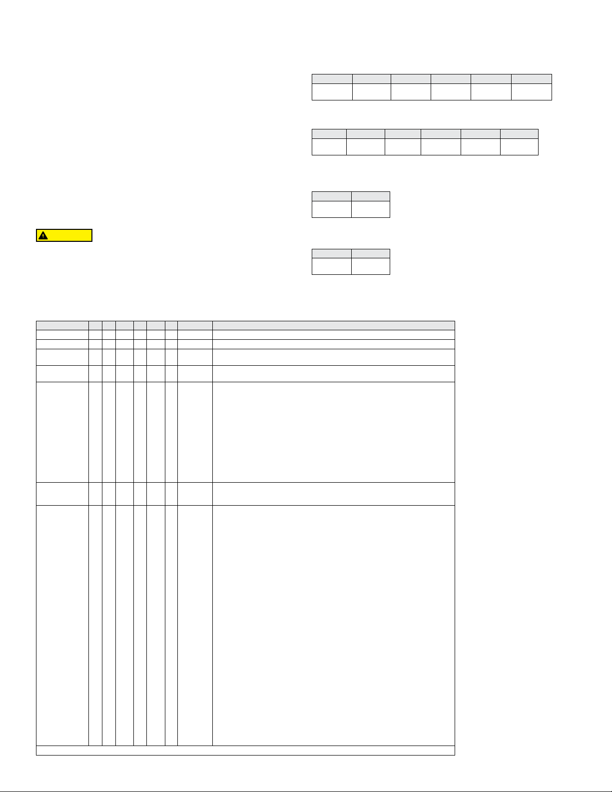
Beispiel V6 EP -BB -D -1 -B - AT V6EPB-B-D-1-B-AT
Serie V6 Flotect
Zur Vermeidung von Bränden in explosionsgefährdeten
Umgebungen unterbrechen Sie die Spannungsversorgung, bevor
Sie den Durchusswächter öffnen. Halten Sie das Gerät beim
®
Mini-Größe Durchusswächter
V6 mit T-Stück
Kaltes Wasser - werkseitiges T-Stück
Ungefährer Ein-/Ausschaltpunkt
GPM oben M3/HR unten
Luft - werkseitiges T-Stück
Ungefährer Ein-/Ausschaltpunkt
SCFM oben, NM3/M unten
V6 LF, einstellbar
Kaltes Wasser - LF-Modelle
Ungefährer Ein-/Ausschaltpunkt
GPM oben M3/HR unten
Luft - LF-Modelle
Ungefährer Ein-/Ausschaltpunkt
SCFM oben, NM3/M unten
Konstruktion EP Explosionsgeschützt
Gehäuse BB
Schaltertyp D
T-Stück
Anchluss
Größe
T-Stück Typ
und Materia
SS
S
1
2
3
4
5
6
LF
1E
2E
3E
4E
5E
6E
LFE
B
S
O
Optionen 18
20
22
022A
31
AT
BUSH2
BUSH3
BUSH4
BUSH5
BUSH6
BUSH7
BUSH8
BUSH9
BUSH10
BUSH11
CSA
CV
FTR
GL
ID
IEC
JCTLH
KC
MT
MV
NN
ORFB
ORFS
PT
RV
ST
TBC
VIT
Messing
Edelstahl
DPDT
SPDT
1/2˝ NPT
3/4˝ NPT
1˝ NPT
1-1/4˝ NPT
1-1/2˝ NPT
2˝ NPT
LF mit 1/2˝ NPT-Anschlüsse
1/2˝ BSPT**
3/4˝ BSPT**
1˝ BSPT**
1-1/4˝ BSPT**
1-1/2˝ BSPT**
2˝ BSPT**
LF mit 1/2” BSPT Anschlüsse**
Messing
Edelstahl
Kein T-Stück mit Paddel einstellbar
0.18 LF Feder
.020 LF Feder
.022 LF Feder
.022 LF Feder mit Magnet Alnico
.031 LF Feder
ATEX Genehmigung
1/2˝ NPT x 3/4˝ NPT Buchse
1/2˝ NPT x 1˝ NPT Buchse
1/2˝ NPT x 1-1/4˝ NPT Buchse
1/2˝ NPT x 1-1/2˝ NPT Buchse
1/2˝ NPT x 2˝ NPT Buchse
1/2˝ BSPT x 3/4˝ BSPT Buchse, M25 X 1.5 Leitung-Anchlüsse(Conduit)**
1/2˝ BSPT x 1˝ BSPT Buchse, M25 X 1.5 Leitung-Anchlüsse(Conduit)**
1/2˝ BSPT x 1-1/4˝ BSPT Buchse, M25 X 1.5 Leitung-Anchlüsse(Conduit)**
1/2˝ BSPT x 1-1/2˝ BSPT Buchse, M25 X 1.5 Leitung-Anchlüsse(Conduit)**
1/2˝ BSPT x 2˝ BSPT Buchse, M25 X 1.5 Leitung-Anchlüsse(Conduit)**
CSA*
Kundenpaddel
Durchusstestbericht
Erdungskabel*
Kundeninformationen
IECEx Genehmigung
Anschlussdose mit Leitung(Conduit) links
Koreanisch zertizierte(KC)*
Hoch Temperatur*
Goldkontakte
Kein Kundeninformationen*
Orice Messing
Orice Edelstahl
Papieretikett
Verstärktes Paddel
Edelstahletikett
Schraubklemmenanschluss*
Flouroelstomer Dichtungen
*Optionen ohne ATEX und IECEx . **BSPT optionen sind nicht kompatibel mit KC optionen.
1/2˝ NPT 3/4˝ NPT 1˝ NPT 1-1/4˝ NPT 1-1/2˝ NPT 2˝ NPT
1.5 1.0
0.34 0.23
2.0 1.25
0.45 0.28
3.0 1.75
0.68 0.40
4.0 3.0
0.91 0.68
6.0 5.0
1.36 1.14
10.0 8.5
2.27 1.93
1/2˝ NPT 3/4˝ NPT 1˝ NPT 1-1/4˝ NPT 1-1/2˝ NPT 2˝ NPT
6.5 5.0
.18 .14
10.0 8.0
.28 .23
14 12
.40 .34
21 18
.59 .51
33 30
.93 .85
43 36
1.19 1.02
Minimum Maximum
.04 .03
.009 .007
.75 0.60
0.17 0.14
Minimum Maximum
.18 .15
.005 .004
2.70 2.0
.08 .06
Achtung: Geräte ohne AT-Sufx sind
nicht nach 2014/34/EU zertiziert.
Diese Geräte sind für den Einsatz
in explosionsgefährdeten Räumen
nicht geeignet. Sie sind nur nach CE
getestet.
Page 11

V6 mit einstellbarem Paddel
Kaltes Wasser - Messing oder Stahl T-Stueck
Ungefährer Ein-/Ausschaltpunkt
GPM oben M3/HR unten
Luft - Messing- oder Stahl-T-Stück
Ungefährer Ein-/Ausschaltpunkt
SCFM oben, NM
3
/M unten
Platte 1/2˝ NPT 3/4˝ NPT 1˝ NPT 1-1/4˝ NPT 1-1/2˝ NPT 2˝ NPT
Volle
Größe
a 9,5 9,0
b 10,0 9,3
c 11,0 10,0
d 6,2 5,5
e 7,0 6,5
f 4,3 3,9
g 4,9 4,4
h 5,5 5,0
i 3,5 3,1
j 4,0 3,5
k 4,6 4,2
l 2,6 2,3
m 1,6 1,3
n 2,2 1,8
o 3,0 2,4
0,4 0,3
0,5 0,4
0,7 0,5
0,6 0,5
3,5 3,1
0,8 0,7
4,3 3,8
1,0 0,9
0,8 0,7
0,9 0,8
1,04 0,95
5,6 5,2
1,3 1,2
6,3 6,1
1,43 1,39
8,0 7,5
1,8 1,7
1,0 0,9
1,1 1,0
1,2 1,1
6,0 5,6
1,4 1,3
7,0 6,6
1,6 1,5
8,0 7,6
1,8 1,7
10,0 9,0
2,3 2,0
12,0 10,0
2,7 2,3
1,4 1,2
1,6 1,5
7,6 7,1
1,7 1,6
8,0 7,3
1,8 1,7
9,0 8,2
2,0 1,9
10,0 9,0
2,3 2,0
13,0 11,0
3,0 2,5
15,0 13,0
3,4 3,0
9,0 8,5
2,0 1,9
2,2 2,0
2,3 2,1
2,5 2,3
12,0 10,0
2,7 2,3
13,0 11,0
3,0 2,5
14,0 12,0
3,2 2,7
Platte 1/2˝ NPT 3/4˝ NPT 1˝ NPT 1-1/4˝ NPT 1-1/2˝ NPT 2˝ NPT
Volle
Größe
a 40,0 38,0
b 42,0 40,0
c 50,0 44,0
d 27,0 25,0
e 30,0 28,0
f 20,0 18,0
g 21,0 19,0
h 23,0 21,0
i 16,0 15,0
j 18,0 16,0
k 19,0 17,0
l 13,0 12,0
m 6,4 3,8
n 10,0 7,0
o 12,0 9,0
0,18 0,11
0,28 0,20
0,34 0,25
0,37 0,34
15,0 14,0
0,42 0,40
20,0 16,0
0,57 0,45
0,45 0,42
0,51 0,45
0,54 0,48
22,0 20,0
0,62 0,57
25,0 23,0
0,71 0,65
32,0 28,0
0,91 0,79
0,57 0,51
0,59 0,54
0,65 0,59
24,0 22,0
0,68 0,62
28,0 25,0
0,79 0,71
33,0 30,0
0,93 0,85
38,0 35,0
1,08 0,99
45,0 42,0
1,27 1,19
0,76 0,71
0,85 0,79
32,0 30,0
0,85 0,79
32,0 30,0
0,91 0,85
34,0 32,0
0,96 0,91
37,0 34,0
1,05 0,96
39,0 36,0
1,10 1,02
51,0 45,0
1,44 1,27
69,0 57,0
1,95 1,61
39,0 37,0
1,10 1,05
1,13 1,08
1,19 1,13
1,42 1,25
55,0 46,0
1,56 1,30
Kaltes Wasser - Edelstahl o. Schmiedest. gerades T-Stück und Muffe
Ungefährer Ein-/Aussschaltpunkt
GPM oben M
3
/HR unten
Platte 1/2˝ NPT 3/4˝ NPT 1˝ NPT 1-1/4˝ NPT 1-1/2˝ NPT 2˝ NPT
Volle
Größe
a 5,5 5,0
b 6,2 5,7
c 6,8 6,3
d 2,8 2,4
e 3,4 3,0
f 4,0 3,6
g 2,0 1,5
h 2,5 2,0
i 3,5 3,0
j 7,0 5,5
k 10,0 8,0
0,5 0,3
0,6 0,5
0,8 0,7
1,6 1,2
2,3 1,8
0,6 0,5
0,8 0,7
0,91 0,82
5,0 3,6
1,1 1,0
6,5 6,1
1,48 1,39
9,0 8,2
2,0 1,9
5,0 4,5
1,1 1,0
1,2 1,1
1,4 1,3
1,5 1,4
8,5 7,8
1,9 1,8
10,0 9,2
2,3 2,1
12,0 10,0
2,7 2,3
8,5 7,8
1,9 1,8
9,2 8,6
2,1 2,0
9,8 9,0
2,2 2,0
12,0 10,0
2,7 2,3
13,0 11,0
3,0 2,5
Luft - Edelstahl o. Schmiedest. gerades T-Stück und Muffe
Ungefährer Ein-/Ausschaltpunkt
SCFM oben, NM3/M unten
Platte 1/2˝ NPT 3/4˝ NPT 1˝ NPT 1-1/4˝ NPT 1-1/2˝ NPT 2˝ NPT
Volle
Größe
a 22,0 20,0
b 24,0 22,0
c 28,0 26,0
d 12,0 10,0
e 14,0 12,0
f 16,0 14,0
g 8,0 6,5
h 11,0 10,0
i 14,0 13,0
j 27,0 24,0
k 39,0 36,0
0,23 0,18
0,31 0,28
0,40 0,37
0,76 0,68
1,10 1,02
0,34 0,28
0,40 0,34
0,45 0,40
19,0 17,0
0,54 0,48
26,0 24,0
0,74 0,68
32,0 30,0
0,91 0,85
21,0 18,0
0,59 0,51
0,62 0,57
0,68 0,62
0,79 0,74
33,0 30,0
0,93 0,85
37,0 34,0
1,05 0,96
43,0 40,0
1,22 1,13
33,0 30,0
0,93 0,85
39,0 36,0
1,10 1,02
42,0 38,0
1,19 1,08
51,0 46,0
1,44 1,30
55,0 50,0
1,56 1,42
Page 12
ABMESSUNGEN
.625
[47.62]
DPDT
3/4˝ NPT
[136.5]
"A"
3-3/8 [85.72] DIA.
F
[235.0]
"A"
3-3/8 [85.72]
1/2˝ NPTF
. ERDUNG
1/2˝ NPTF
AUSLAUF
1/2˝ NPTF
5-13/16
[147.69]
TERUNG
Serie V6 Flotect
3-15/16
[100.0]
4-1/2
[114.3]
EINLAUF
®
Durchusswächter
3-5/8 [92.07]
V6 LF
3/4˝ NPT
1-1/8 SQ.
[28.57]
DIA.
7.250
[184.2]
8-5/8
[219.1]
1-1/8 SQ.
EINLAUF
V6 LF mit CSA, IECEx, ATEX Schutzgehaeuse
3-5/8 [92.07]
[28.57]
6-1/8
[155.5]
AUSLAUF
1/2˝ NPTF
13/16 [20.63]
EXT
3/4˝ NPTF
SCHLIESSRINGANORDNUNG
3/4 NPT
OBERES GEHÄUSE
SCHALTERHALTERUNG
SPDT (ODER DPDT)
SCHNAPPSCHALTER
MAGNET-HEBELSTIFT
MAGNETHEBELANORDNUNG
MAGNETE
UNTERES GEHÄUSE MES-SING ODER EDELSTAHL
SCHIEBERFEDER
SCHIEBER-ACHSE
SCHIEBER-DREHHAL
FEDERRING
1/2 NPT
EDELSTAHLSCHIEBER
GESAMTLÄNGE MIT
1-1/4 T-VERBINDUNG
ETWA 8
V6 mit einstellbarem Paddel
Messing/Eisen Edelstahl/Schmiedest Gusseisen
Rohr
Größe
Abm. A Abm. B Abm. A Abm. B Abm. A Abm. B
1/2˝
2-1/4 [57]
3/4˝
2-3/8 [60]
1˝
2-1/2 [64]
1-1/4˝
2-5/8 [67]
1-1/2˝
2-7/8 [73]
2˝
3 [76]
5-3/8
"B"
1-1/8 [29]
1-1/4 [32]
1-3/8 [35]
1-1/2 [38]
1-5/8 [41]
1-7/8 [48]
V6 mit T-Stück
2-1/4 [57]
2-5/8 [67]
3 [76]
3-1/2 [89]
4 [102]
4-3/4 [121]
1-1/8 [29]
1-7/8 [47]
2-1/8 [54]
2-1/2 [64]
2-3/4 [70]
3-1/8 [79]
2-1/2 [64]
2-5/8 [67]
2-7/8 [73]
3 [76]
3-1/4 [83]
3-1/2 [89]
1-1/4 [32]
1-3/8 [35]
1-1/2 [38]
1-3/4 [44]
1-7/8 [48]
2-1/8 [54]
9-1/4
"B"
V6 mit T-Stück für CSA-, IECEx,
ATEX- Gehäuse
13/16 [20.63]
3/4 NPT
[15.87]
1.875
Einstellbares Paddel
SPDT
Klemmleisten
für CSA-, IECEx, und ATEX-Modelle
DWYER INSTRUMENTS, INC.
P.O. BOX 373 • MICHIGAN CITY, INDIANA 46360, U.S.A.
Telefon: 219-879-8000
Fax: 219-872-9057
www.dwyer-inst.com
e-mail: [email protected]
Page 13
Interruptor de caudal Flotect® serie V 6
DETALLE DE LA VISTA FRONTAL DETALLE DE LA VISTA LATERAL
ARANDELA DE RETENCIÓN
OR
Specications - Installation and Operating Instructions
Boletín E-22
El interruptor de caudal Flotect® serie V6 es un interruptor de caudal económico, a
prueba de explosiones para uso en aire, agua u otros gases y líquidos compatibles.
Hay tres conguraciones disponibles: 1. Con “T” instalada en fábrica. 2. Con paleta
recortable para ajuste en campo e instalación en una “T” adecuada. 3. Modelos de
bajo caudal con una “T” integral y una válvula ajustable. Todas están disponibles con
una caja homologada con UL y CSA o que cumple con la Directiva 2014/34/EU (ATEX)
para 2813 II 2 G Ex db IIC T6 Gb Temperatura de proceso ≤75 °C o que cumple
con IECEx para Ex db IIC T6 Gb Temperatura de proceso ≤ 75 °C.
INSTALACIÓN
Desempaque y quite cualquier material de empaque que se encuentre dentro del
alojamiento inferior o en la “T”.
El interruptor puede instalarse en cualquier posición, pero los caudales de activación y
desactivación en las tablas se basan en tendidos de tubería horizontales y son valores
nominales. Para obtener ajustes más precisos, las unidades pueden calibrarse en
fábrica para caudales especícos.
Los modelos V6 con “T” se ofrecen en tamaños NPT de 1/2˝ - 2˝. Instale en la
tubería con la echa indicadora en la dirección del caudal.
Los modelos V6 de bajo caudal tienen conexiones NPT de 1/2˝ y son ajustables en
campo. Instale en la tubería con la echa indicadora en la dirección del caudal. Para
ajustar, aoje los cuatro tornillos de la base del fondo. La válvula de ajuste gira 90°
entre “O” (abierto) y “C” (cerrado). Vea las tablas de caudal para valores aproximados.
Apriete los tornillos una vez ajustados los puntos de caudal.
V6 con paleta recortable en campo. Estos modelos permiten al instalador
seleccionar los puntos de actuación/desactuación aproximados recortando los tramos
de la paleta según las marcas con letras en una plantilla extraíble. Los caudales se
denen en las tablas de más abajo. Tenga en cuenta que las tablas están basadas en
“Tes” reductoras de latón o hierro fundido, o “Tes” rectas de acero inoxidable o forjado
con bujes donde sean necesarios. Instale en la tubería con la echa indicadora en la
dirección del caudal.
Cuando se usen casquillos, se deben taladrar por detrás para permitir una holgura
apropiada, a n de lograr el libre movimiento de la paleta. Deje un diámetro interior
de 20 mm en bujes de 1/2˝ x 3/4˝ o 25 mm en bujes más grandes. La profundidad del
oricio debe dejar roscas internas de 14 mm de altura para lograr una unión adecuada
entre el buje y la parte inferior del interruptor. Verique el movimiento de la paleta y el
funcionamiento del interruptor después de la instalación.
CONEXIONES ELÉCTRICAS
Conecte los contactos del cable de acuerdo con los códigos eléctricos locales y
según la acción requerida del interruptor. Los contactos abiertos se cerrarán y los
contactos cerrados se abrirán cuando el caudal aumente hasta el punto de actuación.
Regresarán al estado “normal” cuando el caudal disminuya hasta el punto de
desactuación. Negro = común, Azul = abierto y Rojo = cerrado.
Para los equipos que se suministren con tomas de tierra interna y externa, el tornillo
de tierra del interior del alojamiento debe usarse para conectar el control a tierra.
El tornillo de conexión externo es para realizar una conexión adicional cuando sea
permitido o requerido por las normas locales. Cuando se requiere el conductor de
conexión externo, este debe envolverse un mínimo de 180° alrededor del tornillo
de conexión externo. Ver a continuación. Algunos modelos listados en CSA se
proporcionan con un cable verde separado de conexión a tierra. Tales unidades deben
equiparse con una caja de unión, que no se suministra, pero que se encuentra dis
ESPECIFICACIONES
Servicio: Gases o líquidos compatibles con los materiales mojados.
Materiales mojados: Modelos V6 estándares: Aleta: acero inoxidable 301; cuerpo
inferior: latón o acero inoxidable 303; imán: cerámico; otro: acero inoxidable 301,
302; “T”: latón, hierro, acero forjado o acero inoxidable 304: Modelos V6 de bajo
caudal: cuerpo inferior: latón o acero inoxidable 303; “T”: latón o acero inoxidable
304; imán: cerámico; junta tórica: Buna-N estándar, uoroelastómero opcional; otro:
acero inoxidable 301, 302.
Límites de temperatura: -20 a 105°C (-4 a 220°F) estándar, opción de alta
temperatura MT 205°C (400°F) (MT no cumple con UL, CSA, ATEX, IECEx o
KC), AT conforme a ATEX, IEC conforme a IECEx y KC (opción KC); temperatura
ambiente -20 a 75°C (-4 a 167°F); temperatura del proceso: -20 a 105°C (-4 a
220°F).
Límite de presión: Modelos de cuerpo inferior de latón sin “T”, 1000 psig (69 bar),
modelos de cuerpo inferior de acero inoxidable 303 sin “T”, 2000 psig (138 bar).
Modelos con “T” de latón, 250 psi (17,2 bar), modelos con “T” de hierro, 1000 psi
(69 bar), modelos con “T” de acero forjado o acero inoxidable, 2000 psi (138 bar),
modelos de bajo caudal, 1450 psi (100 bar).
Clasicación de gabinete: Resistente a la intemperie y a prueba de explosiones:
Homologado por UL y CSA para clase I, grupos A, B, C y D; clase II grupos E, F y
G. (Grupo A sólo en modelos con cuerpo de acero inoxidable).
2813 II 2 G Ex db IIC T6 Gb Temperatura de proceso ≤75 °C Clase
de temperatura alternativa T5 Temperatura de proceso ≤90 °C, 115 °C (T4)
Temperatura de proceso ≤105 °C consulte a la fábrica. Núm. certicado tipo EU:
KEMA 04ATEX2128.
Estándares ATEX: EN60079-0:2012 +A11: 2013; EN60079-1: 2014.
Certicación IECEx: Para Ex db IIC T6 Gb Temperatura de proceso ≤75 °C
Clase de temperatura alternativa T5 Temperatura de proceso ≤90 °C, 115 °C (T4)
Temperatura de proceso ≤105 °C consulte a la fábrica.
Certicado de cumplimiento IECEx: IECEx DEK 11.0039; Normas IECEx: IEC
60079-0: 2011; IEC 60079-1: 2014; Certicación coreana (KC): Ex d IIC T6 Gb
Temperatura de proceso ≤75°C (167° F); Certicado KTL número: 12-KB4BO-0091.
Tipo de interruptor: Interruptor de acción rápida 1P2T estándar, interruptor de
acción rápida 2P2T opcional.
Clasicación eléctrica: modelos UL: 5 A @125/250 VCA. Modelos CSA, ATEX
y IECEx: 5 A @ 125/250 VCA (V~); 5 A resistivo, 3 A inductivo @ 30 VCC (V ).
Opción MV: 0,1 A @ 125 VCA (V~). Opción MT: 5 A @125/250 VCA (V~). [Opción
MT no aprobada por UL, CSA, ATEX o IECEx].
Conexiones eléctricas: modelos UL: 18 AWG, 460 mm de longitud. Modelos
ATEX/CSA /IECEx: bloque de terminales.
Cuerpo superior: Latón o acero inoxidable 303.
Conexiones de conducto: NPT macho de 3/4˝ estándar, NPT hembra de 3/4˝ en
modelos con caja de unión o M25 x 1,5 con opción de - BSPT.
Conexión de proceso: NPT macho de 1/2˝ en modelos sin “T”.
Orientación de montaje: El interruptor puede instalarse en cualquier posición,
pero los caudales de activación y desactivación en las tablas se basan en tendidos
de tubería horizontales y son valores nominales.
Regulación de punto de ajuste: Modelos V 6 estándar, ninguno. En los modelos
sin “T”, la aleta es ajustable. Los modelos de bajo caudal pueden ajustarse en
campo dentro del rango mostrado. Consulte las tablas de puntos de ajuste en la
página opuesta.
Peso: 0,9 a 2,7 kg dependiendo de la fabricación.
Opciones no mostradas: Calibración especial, bujes, “T” de PVC, aleta reforzada,
relés 2P2T.
CONDUCT
ABRAZADERA
DWYER INSTRUMENTS, INC.
P.O. BOX 373 • MICHIGAN CITY, INDIANA 46360, U.S.A.
Teléfono: 219-879-8000
Fax: 219-872-9057
TORNILLO
www.dwyer-inst.com
correo electrónico:
Page 14
Instrucciones de instalación del certicado EU-Type, IECEx y KC:
Conexión del cable
El dispositivo de entrada de cable debe tener certicación para caja resistente al
fuego con protección contra explosiones tipo “d”, adecuada para las condiciones de
uso e instalada correctamente. Para temperaturas ambiente ≥ 65 °C se deben usar
cables y prensas aptos para ≥ 90 °C.
Conexión de conducto
Se debe usar un dispositivo con certicación Ex d, como por ejemplo, un sello
de conducto con un compuesto endurecedor inmediatamente en la entrada del
compar timento de la válvula. Para temperaturas ambiente ≥ 65 °C se deben usar
cables y un compuesto endurecedor, en el sello de conducto, con clasicación hasta
≥ 90 °C.
Nota: s olo pa r a e quip o s ATEX, IECEx y KC: La cl ase de te mper atur a está de ter mina d a
por la temperatura máxima ambiente o de proceso. Las unidades están hechas para
usarse en ambientes de -20 °C≤ Temp. amb. ≤75 °C. Las unidades pueden usarse en
temperaturas de proceso de hasta 105 °C siempre que la temperatura de la caja y del
cuerpo del interruptor no supere los 75 °C. La clase de temperatura estándar es T6,
temperatura de proceso ≤75 °C. Se encuentran disponibles la clase de temperatura
alternativa T5 Temperatura de proceso de ≤90 °C y 115 °C (T4) Temperatura de
proceso de ≤105 °C, consulte a la fábrica.
Consulte el n.º de certicado: IECEx DEK 11.0039 para conocer las condiciones de
uso seguro de las unidades que cumplen con IECEx.
Todos los cables, conductores y cajas deben cumplir los códigos vigentes para áreas
peligrosas. Los conductores y cajas deben estar adecuadamente sellados. Para
exteriores o para otros lugares en los que las temperaturas varíen ampliamente,
se deben tomar las precauciones para prevenir condensaciones en el interior del
interruptor o de la caja. Los componentes eléctricos se deben mantener secos en
todo momento.
PRECAUCIÓN
abrirlo. Mantenga el conjunto herméticamente cerrado cuando esté en uso.
MANTENIMIENTO
Inspeccione y limpie las piezas mojadas a intervalos regulares. La tapa debe estar
colocada en todo momento, a n de proteger los componentes internos de la suciedad,
el polvo, el clima, y para mantener las clasicaciones para ubicaciones peligrosas.
Desconecte el dispositivo del circuito de la fuente de alimentación antes de abrirlo,
a n de evitar incendios en una atmósfera peligrosa. Las reparaciones deben ser
realizadas por Dwyer Instruments, Inc. Las unidades para reparación deben enviarse
prepagadas a la fábrica.
Ejemplo V6 EP -BB -D -1 -B -AT V6EPB-B-D-1-B-AT
Serie L6 Flotect
Fabricación EP A Prueba de Explosiones
Cuerpo BB
Tipo de circuito (interruptor) D
tamaño de conexión de “T” 1
Material et Tipo
de “T”
Opciones 18
*Opciones que no tienen ATEX o IECEx. **BSPT opciones no son compatibles con le KC opcione.
Para evitar incendios en atmósferas peligrosas, desconecte el
dispositivo del circuito de la fuente de alimentación antes de
®
Interruptor de caudal mini-tamaño
SS
S
2
3
4
5
6
LF
1E
2E
3E
4E
5E
6E
LFE
B
S
O
20
22
022A
31
AT
BUSH2
BUSH3
BUSH4
BUSH5
BUSH6
BUSH7
BUSH8
BUSH9
BUSH10
BUSH11
CSA
CV
FTR
GL
ID
IEC
JCTLH
KC
MT
MV
NN
ORFB
ORFS
PT
RV
ST
TBC
VIT
Latón
Acero inoxidable
1P2T
2P2T
NPT de 1/2˝
NPT de 3/4˝
NPT de 1˝
NPT de 1-1/4˝
NPT de 1-1/2˝
NPT de 2˝
Bajo caudal con entrada y salida NPT de 1/2˝
BSPT de 1/2˝**
BSPT de 3/4˝**
BSPT de 1˝**
BSPT de 1-1/4˝**
BSPT de 1-1/2˝**
BSPT de 2˝**
Bajo caudal con entrada y salida BSPT de 1/2˝**
Latón
Acero inoxidable
Sin “T” con aleta recortable en campo
Resorte de 0,018 para bajo caudal
Resorte de 0,020 para bajo caudal
Resorte de 0,022 para bajo caudal
Resorte de 0,022 para bajo caudal con imán de Alnico
Resorte de 0,031 para bajo caudal
Approbado ATEX
1/2˝ NPT x 3/4˝ NPT Cojinete
1/2˝ NPT x 1˝ NPT Cojinete
1/2˝ NPT x 1-1/4˝ NPT Cojinete
1/2˝ NPT x 1-1/2˝ NPT Cojinete
1/2˝ NPT x 2˝ NPT Cojinete
1/2˝ BSPT x 3/4˝ BSPT Cojinete, M25 X 1.5 Conexión de conducto (Conduit)**
1/2˝ BSPT x 1˝ BSPT Cojinete, M25 X 1.5 Conexión de conducto (Conduit)**
1/2˝ BSPT x 1-1/4˝ BSPT Cojinete, M25 X 1.5 Conexión de conducto (Conduit)**
1/2˝ BSPT x 1-1/2˝ BSPT Cojinete, M25 X 1.5 Conexión de conducto (Conduit)**
1/2˝ BSPT x 2˝ BSPT Cojinete, M25 X 1.5 Conexión de conducto (Conduit)**
Approbado CSA*
Aleta Personalizada
Informe de prueba de caudal
Cable a tierra*
Placa estándar con información del cliente
Approbado IECEx
Caja de unión con lado izquierdo conducto
Certicación coreana(KC)*
Alta temperatura*
Microcontactos dorados
Sin Placa estándar con información del cliente*
Oricio de latón
Orice de acero inoxidable
Papel etiqueta
Aleta reforzada
Acrero Inoxidable Etiqueta
Conector de bloque de terminales*
Sellos Flouroelstomer
V6 con “T”
Agua fría: “T” instalada en fábrica
Caudales aproximados de actuación/desactuación
Superior en GPM, inferior en M3/HR
NPT de 1/2˝ NPT de 3/4˝ NPT de 1˝ NPT de 1-1/4˝ NPT de 1-1/2˝ NPT de 2˝
1.5 1.0
0.34 0.23
Aire: “T” instalada en fábrica
Caudales aproximados de actuación/desactuación
Superior en SCFM, inferior en NM3/M
NPT de 1/2˝ NPT de 3/4˝ NPT de 1˝ NPT de 1-1/4˝ NPT de 1-1/2˝ NPT de 2˝
6.5 5.0
.18 .14
V6 bajo caudal, ajustable en campo
Agua fría: modelos de bajo caudal
Caudales aproximados de actuación/desactuación
Superior en GPM, inferior en M3/HR
Mínimo Máximo
.04 .03
.009 .007
Aire: Modelos de bajo caudal
Caudales aproximados de actuación/desactuación
Superior en SCFM, inferior en NM3/M
Mínimo Máximo
.18 .15
.005 .004
2.0 1.25
0.45 0.28
10.0 8.0
.28 .23
.75 0.60
0.17 0.14
2.70 2.0
.08 .06
3.0 1.75
0.68 0.40
14 12
.40 .34
4.0 3.0
0.91 0.68
21 18
.59 .51
6.0 5.0
1.36 1.14
33 30
.93 .85
Atención: Las
unidades sin el sujo
“AT” no cumplen con
la Directiva 2014/34/
EU (ATEX). Estas
unidades no son
aptas para usarse
en atmósferas
potencialmente
peligrosas en la
UE. Estas unidades
pueden tener la
marca CE para otras
Directivas de la UE.
10.0 8.5
2.27 1.93
43 36
1.19 1.02
Page 15

V6 con paleta recortable en campo
Agua fría: “T” reductora de latón o de hierro fundido
Caudales aproximados de actuación/desactuación
Superior en GPM, inferior en M3/HR
Aire: “T” reductora de latón o de hierro fundido
Caudales aproximados de actuación/desactuación
Superior en SCFM, inferior en NM
3
/M
Aleta 1/2˝ NPT 3/4˝ NPT 1˝ NPT 1-1/4˝ NPT 1-1/2˝ NPT 2˝ NPT
Tamaño
Completo
a 9.5 9.0
b 10.0 9.3
c 11.0 10.0
d 6.2 5.5
e 7.0 6.5
f 4.3 3.9
g 4.9 4.4
h 5.5 5.0
i 3.5 3.1
j 4.0 3.5
k 4.6 4.2
l 2.6 2.3
m 1.6 1.3
n 2.2 1.8
o 3.0 2.4
0.4 0.3
0.5 0.4
0.7 0.5
0.6 0.5
3.5 3.1
0.8 0.7
4.3 3.8
1.0 0.9
0.8 0.7
0.9 0.8
1.04 0.95
5.6 5.2
1.3 1.2
6.3 6.1
1.43 1.39
8.0 7.5
1.8 1.7
1.0 0.9
1.1 1.0
1.2 1.1
6.0 5.6
1.4 1.3
7.0 6.6
1.6 1.5
8.0 7.6
1.8 1.7
10.0 9.0
2.3 2.0
12.0 10.0
2.7 2.3
1.4 1.2
1.6 1.5
7.6 7.1
1.7 1.6
8.0 7.3
1.8 1.7
9.0 8.2
2.0 1.9
10.0 9.0
2.3 2.0
13.0 11.0
3.0 2.5
15.0 13.0
3.4 3.0
9.0 8.5
2.0 1.9
2.2 2.0
2.3 2.1
2.5 2.3
12.0 10.0
2.7 2.3
13.0 11.0
3.0 2.5
14.0 12.0
3.2 2.7
Aleta 1/2˝ NPT 3/4˝ NPT 1˝ NPT 1-1/4˝ NPT 1-1/2˝ NPT 2˝ NPT
Tamaño
Completo
a 40.0 38.0
b 42.0 40.0
c 50.0 44.0
d 27.0 25.0
e 30.0 28.0
f 20.0 18.0
g 21.0 19.0
h 23.0 21.0
i 16.0 15.0
j 18.0 16.0
k 19.0 17.0
l 13.0 12.0
m 6.4 3.8
n 10.0 7.0
o 12.0 9.0
0.18 0.11
0.28 0.20
0.34 0.25
0.37 0.34
15.0 14.0
0.42 0.40
20.0 16.0
0.57 0.45
0.45 0.42
0.51 0.45
0.54 0.48
22.0 20.0
0.62 0.57
25.0 23.0
0.71 0.65
32.0 28.0
0.91 0.79
0.57 0.51
0.59 0.54
0.65 0.59
24.0 22.0
0.68 0.62
28.0 25.0
0.79 0.71
33.0 30.0
0.93 0.85
38.0 35.0
1.08 0.99
45.0 42.0
1.27 1.19
0.76 0.71
0.85 0.79
32.0 30.0
0.85 0.79
32.0 30.0
0.91 0.85
34.0 32.0
0.96 0.91
37.0 34.0
1.05 0.96
39.0 36.0
1.10 1.02
51.0 45.0
1.44 1.27
69.0 57.0
1.95 1.61
39.0 37.0
1.10 1.05
1.13 1.08
1.19 1.13
1.42 1.25
55.0 46.0
1.56 1.30
Agua fría: “T” recta y buje de acero inoxidable o acero forjado
Caudales aproximados de actuación/desactuación
Superior en GPM , inferior en M
3
/HR
Aleta 1/2˝ NPT 3/4˝ NPT 1˝ NPT 1-1/4˝ NPT 1-1/2˝ NPT 2˝ NPT
Tamaño
Completo
a 5.5 5.0
b 6.2 5.7
c 6.8 6.3
d 2.8 2.4
e 3.4 3.0
f 4.0 3.6
g 2.0 1.5
h 2.5 2.0
i 3.5 3.0
j 7.0 5.5
k 10.0 8.0
0.5 0.3
0.6 0.5
0.8 0.7
1.6 1.2
2.3 1.8
0.6 0.5
0.8 0.7
0.91 0.82
5.0 3.6
1.1 1.0
6.5 6.1
1.48 1.39
9.0 8.2
2.0 1.9
5.0 4.5
1.1 1.0
1.2 1.1
1.4 1.3
1.5 1.4
8.5 7.8
1.9 1.8
10.0 9.2
2.3 2.1
12.0 10.0
2.7 2.3
8.5 7.8
1.9 1.8
9.2 8.6
2.1 2.0
9.8 9.0
2.2 2.0
12.0 10.0
2.7 2.3
13.0 11.0
3.0 2.5
Aire: “T” recta y buje de acero inoxidable o acero forjado
Caudales aproximados de actuación/desactuación
Superior en SCFM, inferior en NM3/M
Aleta 1/2˝ NPT 3/4˝ NPT 1˝ NPT 1-1/4˝ NPT 1-1/2˝ NPT 2˝ NPT
Tamaño
Completo
a 22.0 20.0
b 24.0 22.0
c 28.0 26.0
d 12.0 10.0
e 14.0 12.0
f 16.0 14.0
g 8.0 6.5
h 11.0 10.0
i 14.0 13.0
j 27.0 24.0
k 39.0 36.0
0.23 0.18
0.31 0.28
0.40 0.37
0.76 0.68
1.10 1.02
0.34 0.28
0.40 0.34
0.45 0.40
19.0 17.0
0.54 0.48
26.0 24.0
0.74 0.68
32.0 30.0
0.91 0.85
21.0 18.0
0.59 0.51
0.62 0.57
0.68 0.62
0.79 0.74
33.0 30.0
0.93 0.85
37.0 34.0
1.05 0.96
43.0 40.0
1.22 1.13
33.0 30.0
0.93 0.85
39.0 36.0
1.10 1.02
42.0 38.0
1.19 1.08
51.0 46.0
1.44 1.30
55.0 50.0
1.56 1.42
Page 16
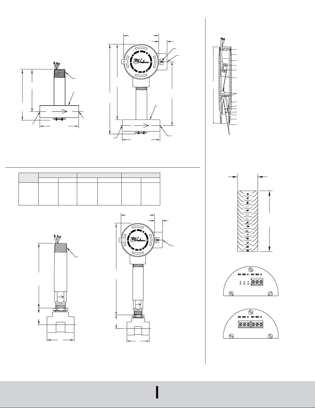
DIMENSIONES
3/4˝ NPT
[136.5]
"A"
3-3/8 [85.72] DIA.
A
[235.0]
"A"
3-3/8 [85.72] DIA.
HEMBRA
A
HEMBRA
A
.625
[47.62]
5-13/16
[147.69]
A
2P2T
Interruptor de caudal Flotect
3-15/16
[100.0]
4-1/2
[114.3]
ENTRADA
1/2˝ NPT
3-5/8 [92.07]
®
serie V6
3/4˝ NPT
1-1/8 SQ.
[28.57]
SALIDA
1/2˝ NPT
HEMBR
8-5/8
[219.1]
ENTRADA
1/2˝ NPT
7.250
[184.2]
3-5/8 [92.07]
1-1/8 SQ.
[28.57]
13/16 [20.63]
CONEX. EXTERN
A TIERRA
6-1/8
[155.5]
SALIDA
1/2˝ NPT
HEMBRA
3/4˝ NPT
HEMBRA
CONJUNTO COLLAR DE BLOQUEO
3/4˝ NPT
SOPORTES INTERRUPTOR
CARCASA SUPERIOR
MICROCONTACTO 1P2T (O 2P2T)
PASADOR DEL BRAZO
DEL IMÁN
CONJUNTO BRAZO DEL IMÁN
IMANES
CARCASA INFERIOR:
LATÓN O ACERO INOXIDABLE
RESORTE DE LA PALETA
PIN DEL PIVOTE DE LA PALETA
ABRAZADERA DEL PIVOTE DE LA PALET
ANILLO
1/2 NPT
PALETA DE ACERO
INOXIDABLE
LONGITUD TOTAL CON "T"
DE CONEXIÓN DE 1-1/4˝
DE APROXIMADAMENTE 8˝
Tamaño
de tubería
1/2˝
3/4˝
1˝
1-1/4˝
1-1/2˝
2˝
V6 Bajo caudal
Latón/hierro dúctil Acero inoxidable/forjado Hierro dúctil
Dim. A Dim. B Dim. A Dim. B Dim. A Dim. B
2-1/4 [57]
2-3/8 [60]
2-1/2 [64]
2-5/8 [67]
2-7/8 [73]
3 [76]
5-3/8
"B"
1-1/8 [29]
1-1/4 [32]
1-3/8 [35]
1-1/2 [38]
1-5/8 [41]
1-7/8 [48]
2-1/4 [57]
2-5/8 [67]
3 [76]
3-1/2 [89]
4 [102]
4-3/4 [121]
V6 de bajo caudal con caja de conductor CSA, IECEx, ATEX
1-1/8 [29]
1-7/8 [47]
2-1/8 [54]
2-1/2 [64]
2-3/4 [70]
3-1/8 [79]
9-1/4
"B"
2-1/2 [64]
2-5/8 [67]
2-7/8 [73]
3 [76]
3-1/4 [83]
3-1/2 [89]
1-1/4 [32]
1-3/8 [35]
1-1/2 [38]
1-3/4 [44]
1-7/8 [48]
2-1/8 [54]
13/16 [20.63]
3/4 NPT HEMBR
V6 con aleta
recortable en campo
[15.87]
1.875
Aleta recortable
1P2T
V6 con “T”
V6 con “T” y caja de conductor
CSA, IECEx, ATEX
DWYER INSTRUMENTS, INC.
P.O. BOX 373 • MICHIGAN CITY, INDIANA 46360, U.S.A.
Conexiones terminales CSA, IECEx,
Printed in U.S.A. 8/21 FR# 4440805-10 Rev. 15©Copyright 2021 Dwyer Instruments, Inc.
Teléfono: 219-879-8000
Fax: 219-872-9057
cajas ATEX
www.dwyer-inst.com
correo electrónico:
 Loading...