

Page 1
MADE IN
User’s Guide
Shop online at
omega.com
e-mail: [email protected]
®
For latest product manuals:
omegamanual.info
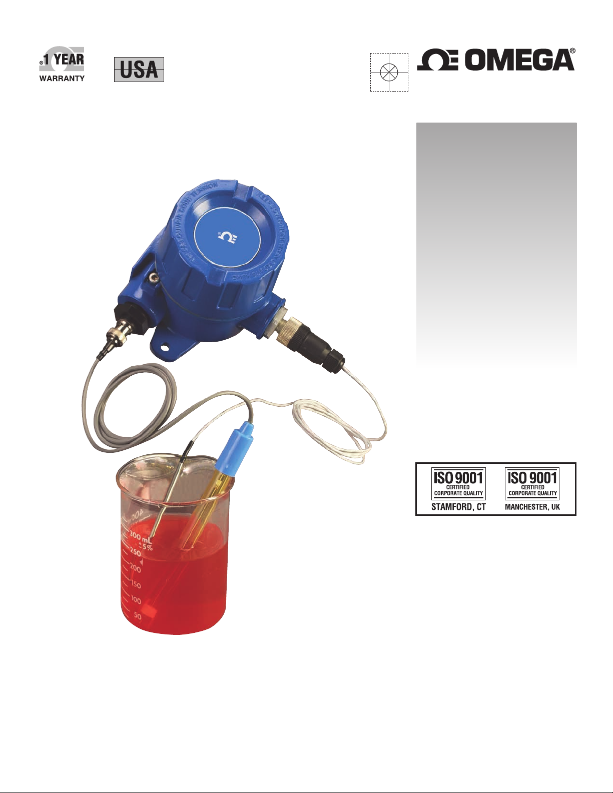
UWXL-24-PH
Long Distance Industrial
Wireless pH Transmitters
Page 2

OMEGAnet®Online Service Internet e-mail
omega.com [email protected]
Servicing North America:
U.S.A.: Omega Engineering, Inc., One Omega Drive, P.O. Box 4047
ISO 9001 Certified Stamford, CT 06907-0047 USA
Canada: 976 Berar
Laval (Quebec), H7L 5A1, Canada
Toll-Free: 1-800-826-6342 TEL: (514) 856-6928
FAX: (514) 856-6886 e-mail: [email protected]
For immediate technical or application assistance:
U.S.A. and Canada: Sales Service: 1-800-826-6342/1-800-TC-OMEGA
Customer Service: 1-800-622-2378/1-800-622-BEST
Engineering Service: 1-800-872-9436/1-800-USA-WHEN
®
®
®
Servicing Asia:
China:: 1698 Yi Shan Road, Unit 102
Min Hang District
Shanghai, China 201103 P.R.C.
Hotline: 800 819 0559/400 619 0559
e-mail: [email protected]
Servicing Europe:
Benelux: Toll-Free: 0800 099 3344 TEL: +31 20 347 21 21
FAX: +31 20 643 46 43 e-mail: [email protected]
Czech Republic: Frystatska 184
733 01 Karviná, Czech Republic
TEL: +420-59-6311899 FAX: +420-59-6311114
e-mail: [email protected]
France: Toll-Free: 0800 541 038 TEL: 01 57 32 48 17
FAX: 01 57 32 48 18 e-mail: [email protected]
Germany/ Austria: Daimlerstrasse 26
D-75392 Deckenpfronn, Germany
Toll-Free: 0800 8266342 TEL: +49 (0) 7056 9398-0
FAX: +49 (0) 7056 9398-29 e-mail: [email protected]
United Kingdom: OMEGA Engineering Ltd.
ISO 9001 Certified One Omega Drive, River Bend Technology Centre, Northbank
Irlam, Manchester M44 5BD United Kingdom
Toll-Free: 0800-488-488 TEL: +44 (0) 161 777-6611
FAX: +44 (0) 161 777-6622 e-mail: [email protected]
It is the policy of OMEGA Engineering, Inc. to comply with all worldwide safety and EMC/EMI
regulations that apply. OMEGA is constantly pursuing certification of its products to the European New
Approach Directives. OMEGA will add the CE mark to every appropriate device upon certification.
The information contained in this document is believed to be correct, but OMEGA accepts no liability for any
errors it contains, and reserves the right to alter specifications without notice.
WARNING: These products are not designed for use in, and should not be used for, human applications.
Page 3

Table of Contents
Section Page
Section 1 Introduction .................................................................................... 1-1
Section 2 Hardware ........................................................................................ 2-1
Section 3 Transmitter Setup and Installation .............................................. 3-1
UWXL-24-PH
Long Distance Industrial Wireless pH Transmitters
1.1 Precautions .......................................................................................... 1-1
1.2 Safety Warnings and IEC Symbols ................................................... 1-1
1.3 Product Labeling ................................................................................ 1-2
1.4 Statement on FCC................................................................................ 1-2
1.5 General Description & System Components ...................................1-2
2.1 Unpacking and Inspection ................................................................ 2-1
2.2 Included Items .................................................................................... 2-1
3.1 Setup and Configuration ................................................................... 3-1
3.2 Mounting, Installation and Antenna Connection .......................... 3-8
3.3 pH and RTD probe Connection ...................................................... 3-10
3.4 Battery Installation or Replacment ................................................ 3-10
Section 4 System Operation ........................................................................... 4-1
4.1 Introduction ......................................................................................... 4-1
4.2 RF Communication Basics ................................................................ 4-1
4.3 Basic System Overview ..................................................................... 4-1
4.4 Transmitter Operation ....................................................................... 4-2
4.5 Environment/Operating Conditions .............................................. 4-3
4.6 Determining and Maximizing Range .............................................. 4-4
4.7 Antenna Basics .................................................................................... 4-6
4.8 Antenna Placement ............................................................................ 4-6
4.9 Factory Preset Values ......................................................................... 4-7
4.10 Transmit Rate vs. Battery Life ......................................................... 4-7
Section 5 Troubleshooting ............................................................................ 5-1
5.1 Transmitter Troubleshooting ............................................................. 5-1
5.2 Receiver Troubleshooting .................................................................. 5-1
Section 6 Service and Calibration ................................................................. 6-1
6.1 Calibration ........................................................................................... 6-1
6.2 Service .................................................................................................. 6-1
Section 7 Specifications .................................................................................. 7-1
7.1 Transmitter Specifications ................................................................. 7-1
7.2 Receiver Specifications ...................................................................... 7-1
Section 8 Approvals & Regulatory Compliance ........................................ 8-1
8.1 FCC (Domestic Use: USA & Canada) .............................................. 8-1
i
Page 4

UWXL-24-PH
Long Distance Industrial Wireless pH Transmitters
List of Figures
Section Figure Description . . . . . . . . . . . . . . . . . . . . . . . . . . . . . . . . Page
1.2 1-1 Main Transmitter Board . . . . . . . . . . . . . . . . . . . . . . 1-1
1.3 1-2 Transmitter Rear Label . . . . . . . . . . . . . . . . . . . . . . . 1-2
1.3 1-3 Transmitter Top Label . . . . . . . . . . . . . . . . . . . . . . . . 1-2
1.5 1-4 System Components . . . . . . . . . . . . . . . . . . . . . . . . . 1-3
3.1 3-1 USB Cable . . . . . . . . . . . . . . . . . . . . . . . . . . . . . . . . . . 3-1
3.1 3-2 Transmitter Mode . . . . . . . . . . . . . . . . . . . . . . . . . . . . 3-3
3.1 3-3 Software - Launch Setup Utility Program Screen . 3-3
3.1 3-4 Software - Welcome Screen . . . . . . . . . . . . . . . . . . . . 3-4
3.1 3-5 Software – Connect To Transmitter Screen . . . . . . . 3-4
3.1 3-6 Software – Setup The End Device Screen . . . . . . . . 3-5
3.1 3-7 Software – Establish A Link Screen . . . . . . . . . . . . . 3-5
3.1 3-8 Software – Choose Options Screen . . . . . . . . . . . . . 3-6
3.1 3-9 Software – Calibration Options Screen . . . . . . . . . . 3-7
3.1 3-10 Software – Send Settings To End Device Screen . . 3-7
3.2 3-11 Software – Mounting Dimensions . . . . . . . . . . . . . . 3-8
3.2 3-12 Software – Fresnel Zone . . . . . . . . . . . . . . . . . . . . . . 3-9
3.4 3-13 Software – Battery Replacement . . . . . . . . . . . . . . . 3-11
4.1 4-1 Basic System Overview . . . . . . . . . . . . . . . . . . . . . . . 4-1
4.4 4-2 UWXL Industrial
Wireless Transmitter Button Options . . . . . . . . . . . 4-1
4.6 4-3 Determining Maximum Range . . . . . . . . . . . . . . . . . 4-4
4.6 4-4 Operation In Buildings . . . . . . . . . . . . . . . . . . . . . . . 4-5
4.8 4-5 Horizontal Antenna Placement . . . . . . . . . . . . . . . . 4-6
4.8 4-6 Vertical Antenna Placement . . . . . . . . . . . . . . . . . . . 4-7
ii
Page 5
Section 1 - Introduction
Please read this manual completely before installing and operating your wireless
End Device and receiver system. It’s important read and follow all notes,
cautions, warnings and safety precautions before operating this End Device.
“End Device” referrers to your transmitter unit.
1.1 Precautions
• This device is not designed for use in any medical or nuclear applications.
• Do not operate this device in flammable or explosive environments.
• Never operate with a power source other than the one recommended in this
manual.
• This device has been designed for dry, moisture free indoor applications only.
• Do not operate this device outside of the recommended use outlined in this
manual.
• No co-location with other radio transmitters is allowed. By definition, colocation is when another radio device or it’s antenna is located within 20 cm
of your End Device and can transmit simultaneously with your End Device.
Introduction
1
• Never install wireless End Devices within 20 cm or less from each other.
• Never install and/or operate your End Device closer than 20 cm to nearby
persons.
• Never use your End Device as a portable device. Your unit has been designed
to be operated in a permanent installation only.
There are no user serviceable parts inside your device.
Attempting to repair or service your unit may void your
warranty.
1.2 Safety Warnings and IEC Symbols
This device is marked with international safety and hazard symbols in
accordance with IEC standards. It is important to read and follow all precautions
and instructions in this manual before operating or commissioning this device as
it contains important information relating to safety and EMC. Failure to follow
all safety precautions may result in injury and or damage to your device. Use of
this device in a manner not specified will void your warranty
IEC symbols Description
NOTE:
Caution, refer to accompanying documentation
EU’s Waste Electrical and Electronic Equipment
Compliance
Figure 1-1. IEC Symbols
1-1
Page 6
1
omega.com
®
Made in U.S.A.
UWXL-24-PH
WIRELESS INDUSTRIAL TRANSMITTER
2.4 GHz
®
This device complies with Part 15 of the FCC rules.
Operation is subject to the following two conditions:
1) This device may not cause harmful interference;
2) This device must accept any interference received,
including interference that may cause undesired
operation.
!
FCC ID: OUR–XBEEPRO
IC #4214A–XBEEPRO
Introduction
1.3 Product Labeling
1.4 Statement on FCC
1.4.1 FCC Marking
FCC ID: OUR-XBEEPRO IC #4214A-XBEEPRO
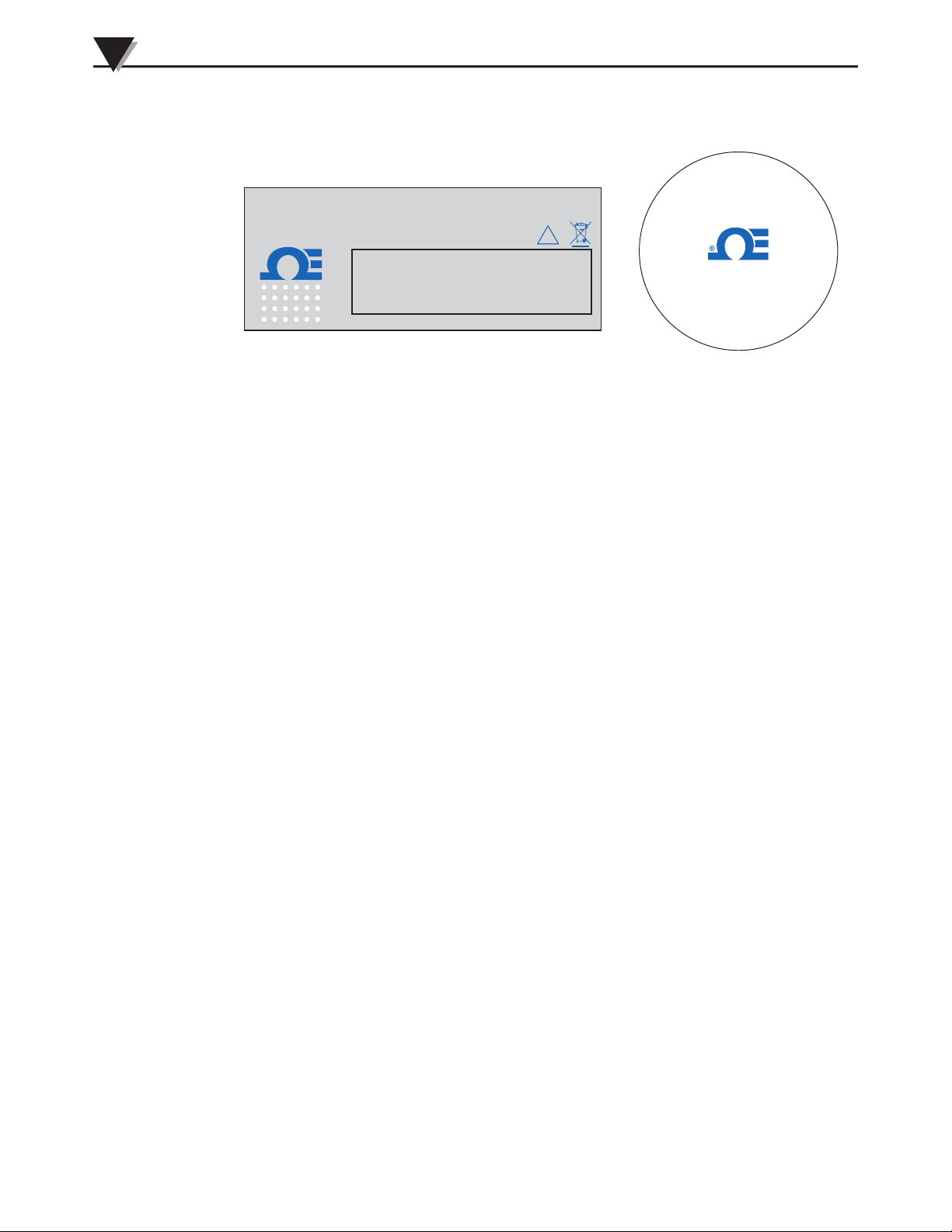
Figure 1-2. Transmitter Rear Label Figure 1-3. Transmitter Top Label
This device complies with Part 15 of the FCC rules. Operation is subject to the
following two conditions: 1.) This device may not cause harmful interference.
2.) This device must accept any interference received, including interference that
may cause undesired operation.
1.5 General Description and System Components
1.5.1 General Description
The UWXL Series Long Distance Industrial Wireless Transmitters are standalone, rugged, battery powered, wireless transmitters that send their
measurements to a host receiver up to 450 m (1500') line of sight (LOS) away.
The UWXL transmitters are designed for a variety of applications, including
temperature (RTD or thermocouple), infrared temperature, relative humidity,
process transducers with standard voltage or current outputs, flow (pulsed
frequency) as well as pH measurement. When activated, the transmitter will
send readings continuously at a pre-set time interval programmed by the user
during initial setup. Each unit measures and transmits: Process value, Ambient
Temperature, RF Signal Strength and Battery Condition to the host. This
information is then displayed on the host PC screen in real time using the
provided software. When used with host receiver model UWXL-REC1, data
from up to 48 wireless end devices can be received and displayed
simultaneously. Each receiver includes free software that converts your PC into a
strip chart recorder or data logger allowing readings to be saved and later
printed or exported to a spread sheet file.accepts a Pt100 RTD probe (mating
connector provided with transmitter).
1-2
Page 7
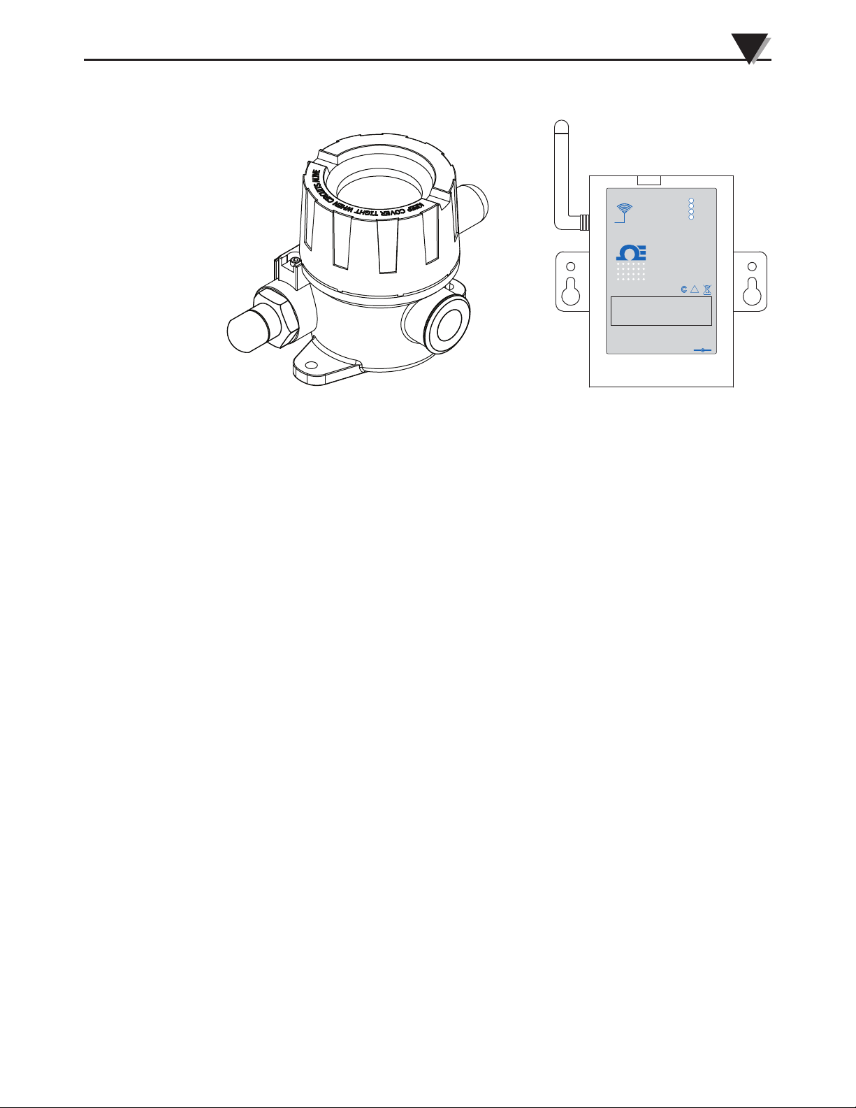
Figure 1-4. System Components
RECEIVER
TRANSMITTER
ANTENNA
USB
I/O
9–24 Vdc
OMEGA ENGINEERING, INC.
Stamford, CT 06907
UWTC SERIES
WIRELESS RF RECEIVER
2.4 GHz
omega.com
Made in U.S.A.
-
+
!
TX
RX
SB
PWR
This device complies with Part 15 of the FCC rules.
Operation is subject to the following two conditions:
1) This device may not cause harmful interference;
2) This device must accept any interference received,
including interference that may cause undesired
operation.
FCC ID: OUR–XBEEPRO
IC #4214A–XBEEPRO
F
®
Introduction
1
1-3
Page 8
2
Hardware
Section 2 – Hardware
It is important that you read this manual completely and follow all safety
precautions before operating this instrument.
2.1 Package Inspection
Remove the packing list and verify that you have received all your equipment. If
you have any questions about the shipment, please call our Customer Service
Department at
1-800-622-2378 or 203-359-1660. We can also be reached on the Internet at
omega.com
e-mail: [email protected]
When you receive the shipment, inspect the container and equipment for any
signs of damage. Note any evidence of rough handling in transit. Immediately
report any damage to the shipping agent.
NOTE:
2.2 Included Items
The following items are supplied in the box.
• 1 UWXL Series transmitter
• 1 User’s Guide
• 1 Battery (inside device)
The carrier will not honor any damage claims unless all
shipping material is saved for inspection. After examining
and removing contents, save packing material and carton in
the event reshipment is necessary.
2-1
Page 9
Section 3 – Setup & Installation
3.1 Setup and Configuration
3.1.1 Connecting your device
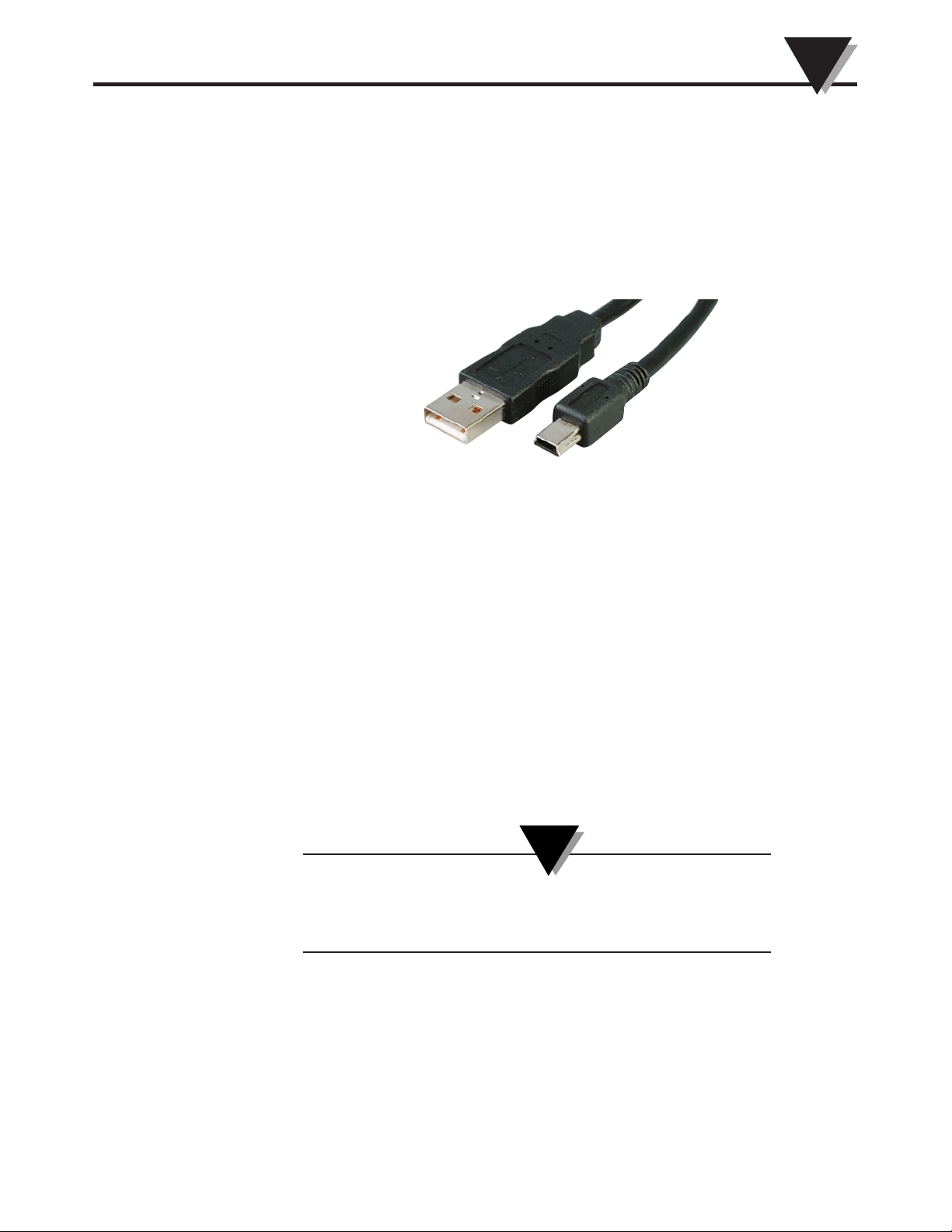
Connect the USB cable to your transmitter unit and also to an available USB port
on your computer. See figure below. The USB cable is provided in the box with
your receiver unit. The same cable is used for programming your transmitter
and for connecting your receiver.
Setup & Installation
Figure 3-1. USB Cable
3
3.1.2 Configure Your End Device
Now that you have connected your USB cable to your PC and transmitter, you
will complete the following steps to configure your End Device before placing
the unit into operation. You will be using the configuration software utility that
you installed onto your PC when you set up your receiver. If you have not
installed the configuration software utility you should do so now. During this
procedure you will be setting the following parameters in your transmitter.
Transmitter Options:
Connector Address
This sets a unique address number into your transmitter. Later, when you set up
your measurement software you will again set channel numbers to receive
readings from the corresponding unit(s). Each end device must be given a
different address for your system to operate correctly
NOTE:
If you will be using more than one receiver unit in your area it
is important to set the transmitter address numbers to be a
corresponding number in your TC-Central software.
Example
For the first receiver: Set the addresses on your transmitters to 101, 102, 103, 104,
etc.
Then set the channels in your TC-Central user software to match.
For the second receiver: Set the addresses on your transmitters to 201, 202, 203,
204, etc.
Then set the channels in your TC-Central user software to match.
3-1
Page 10
3
Transmitter Setup & Installation
This numbering scheme can be expanded to match the number of receivers you
are using.
Sample Rate
This will program your End Device to transmit 1 data reading to your receiver at
a specified time interval. Available settings are 2, 3, 5, 15, 30, 45, 60, 75 or 90
seconds
RF Network Settings:
RF Channel
This setting determines the operating channel on which RF connections are
made between the transmitter and receiver. The transmitter must be set to the
same channel as the receiver in order for them to communicate.
NOTE:
The sample rate you set will have the most direct effect on the
life of the battery in your End Device. It is recommended that
you set the longest sample time that your application can live
with to extend time between battery replacements. See
Section 4 for more information on battery life.
Network ID
This sets the ID of the Network that the transmitter will be joining. It must
match the setting of the receiver in order for them to communicate.
Receiver Address
This sets the destination address for RF packets sent by the transmitter. It must
match the address of the receiver in order for them to communicate.
NOTE:
It is possible to have multiple RF networks operating in the
same vicinity. Each network must have at least one unique RF
Network Setting in order to differentiate the networks.
STEP 1. Enter the “SETUP” mode.
To place your transmitter into the SETUP mode for programming follow this
procedure.
3-2
Page 11
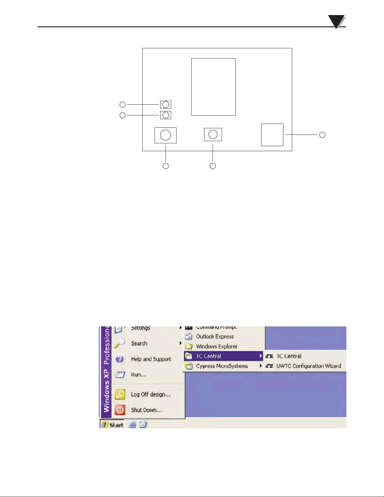
(1) On/Off Button
4
3
5
1
2
(2) Setup Button
(3) Battery Indicator
(4) Status Indicator,
(5) USB Connector
Transmitter Setup & Installation
Figure 3-2. Transmitter Setup Mode
3
Press and hold the ON/OFF button. While the ON/OFF button is being held,
press the SETUP button one time and then release the ON/OFF button. The
green (TX) indicator on the front of your device should be blinking at a steady
rate. This indicates your End Device is ready to run the configuration utility
software
STEP 2. Launch Setup Utility Program.
To launch the End Device setup utility program on your PC begin by accessing
the “Programs” list under your “Start Menu”.
Scroll through the list of to find the Omega TC-Central folder, then select the End
Device Configuration Program.
Figure 3-3. Software - Launch Setup Utility Program Screen
3-3
Page 12
3
Transmitter Setup & Installation
STEP 3. Programming your settings into your End Device
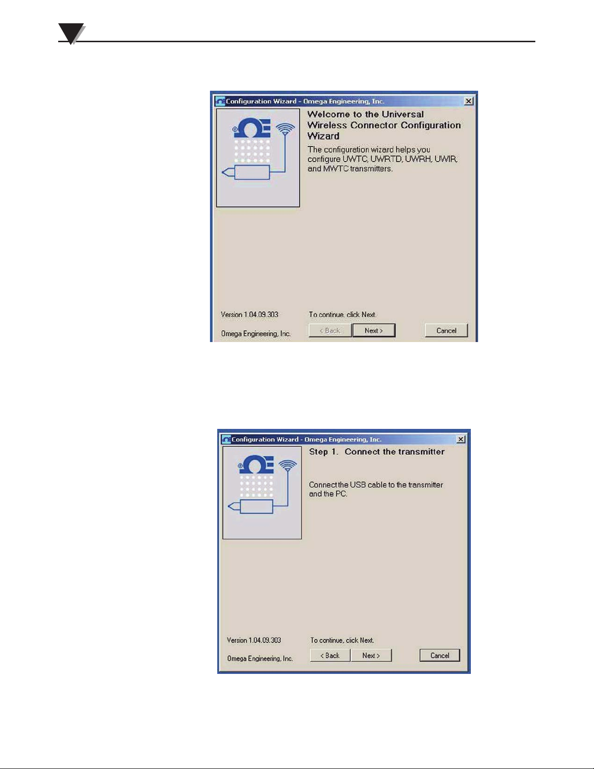
Figure 3-4. Software - Welcome Screen
After starting the setup utility program this will be the first screen you will see.
Click the “Next >” button to proceed and continue setting up your End Device.
Each screen will provide instruction details on how to proceed.
3-4
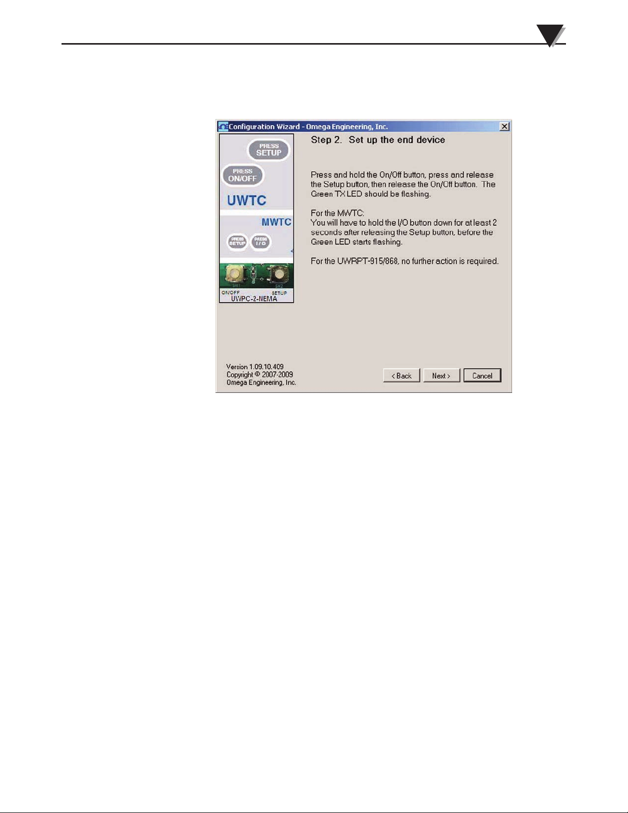
Figure 3-5. Software - Connect To Transmitter Screen
Page 13
Transmitter Setup & Installation
If you have not already connected your End Device to a USB port on your PC
you must do this now before continuing. After your unit has been connected,
click the Next > button to proceed and continue setting up your unit.
3
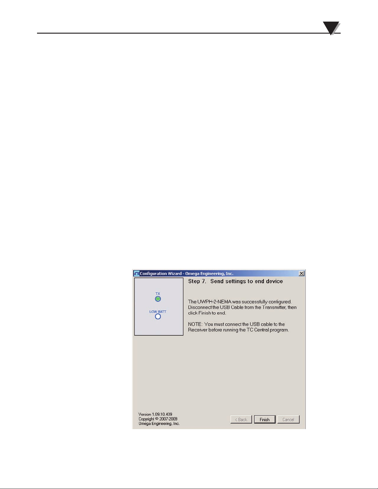
Figure 3-6. Software - Setup The End Device Screen
If you have not already placed your End Device into the SETUP mode you
should do this now before continuing. After your unit has been placed into the
SETUP mode, click the Next > button to proceed and continue setting up your
unit.
Figure 3-7. Software - Establish A Link Screen
3-5
Page 14

3
Transmitter Setup & Installation
After successful communication between your connector/transmitter has been
established you can click the Next > button to proceed and continue setting up
your connector/transmitter. If you did not receive a confirmation of proper
communication you should click the <Back button to try connecting again.
Figure 3-8. Software - Choose Options Screen
From this screen you will select the main operating settings for your end device.
NOTE:
Each end device must have a different address number for
proper operation). After making your selections click the Next
> button to proceed and program your settings into your unit.
3-6
Page 15
Transmitter Setup & Installation
5
Figure 3-9. Software - Calibration Options Screen
This screen lets you select from a number of different calibration options. For pH
you can perform a full 2 point calibration or a simple 1 point offset to account for
sensor drift. For the RTD input you can also perform a 2 point calibration. You can
also choose to restore either input to its factory calibration. Select the calibration
type you wish to perform and click the Next> button and follow the instructions for
calibration. For more information see Section 6, Service and Calibration.
Figure 3-10. Software - Send Settings To End Device Screen
Congratulations! You have successfully programmed your end device. After
your unit has been programmed click the Finish button to close the utility
program.
3-7
Page 16
3
131.8 (5.19)
171.5 (6.75)
DIMENSIONS mm (in)
103.9 (4.09)
105.4 (4.15)
107.95 (4.25)
50.3 (1.98)
Transmitter Setup & Installation
3.2 Mounting, Installation and Antenna Connection
Your device has been shipped to you with a standard antenna already attached.
In some cases the user may wish to install a remote antenna to maximize
transmission range to the receiver. In these instances the UWXL-RAK kit can be
used. The kit includes a direction antenna, 8" extension cable and mounting
bracket.
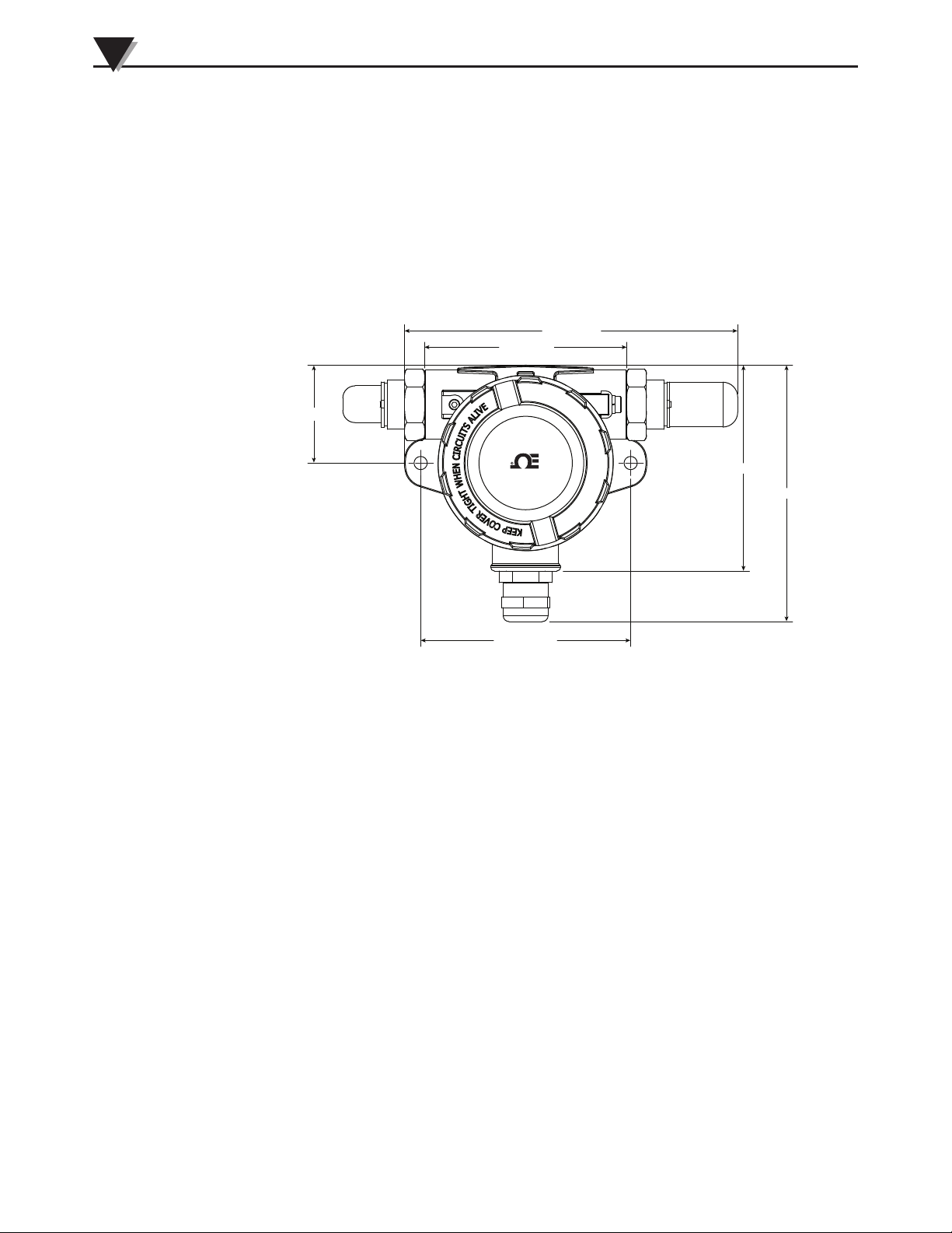
3.2.1 Mounting
The diagram below shows dimensions of the transmitter housing for mounting.
Figure 3-11. Mounting Dimensions
When mounting your end device, care should be taken to make sure it is as far
away from any metal objects. If nearby metal gets too close to your unit, it has
the potential to interfere with the way the unit radiates and may cause signal
lose or possibly even the inability to communicate at all with your receiver.
3.2.2 Installation
When installing your End Device it is important to position your device in such
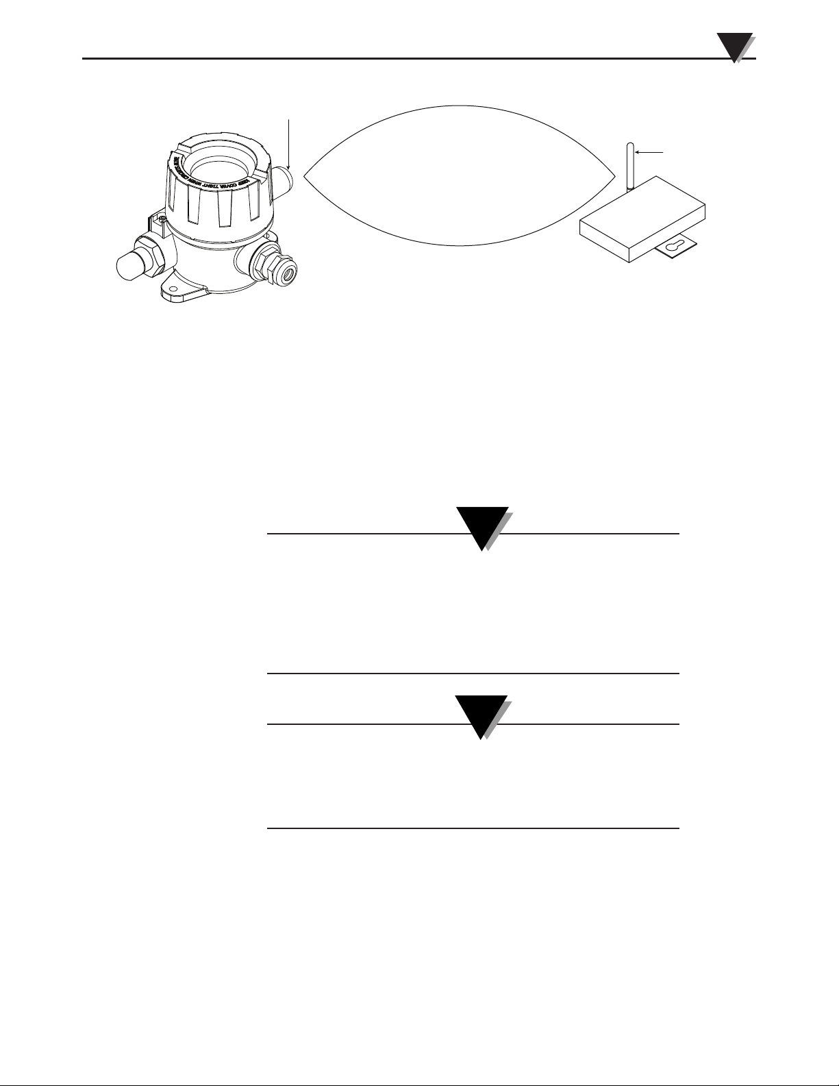
a way as to optimize the antenna location within what’s known as the “Fresnel
Zone”.
The Fresnel Zone can be thought of as a football-shaped invisible tunnel between
two locations that provides a path for RF signals between your End Device and
your receiver.
3-8
Page 17
Transmitter Setup & Installation
REC EIVE R ANT ENNA
TRA NSMI TTER ANTE NNA
Figure 3-12. Fresnel Zone
3
In order to achieve maximum range, the football-shaped path in which radio
waves travel must be free of all obstructions. Obstacles in the path (especially
metal) will decrease the communication range between your End Device and
receiver. Also, If the antennas are mounted just barely off the ground, over half
of the Fresnel zone ends up being obstructed by the earth resulting in significant
reduction in range. To avoid this problem, the antennas should be mounted high
enough off of the ground so that the earth does not interfere with the central
diameter of the Fresnel zone.
NOTE:
It is important to understand that the environment may
change over time due to new equipment or machinery being
installed, building construction, etc. If new obstacles exist
between your End Device and receiver, the devices can be
raised on one end or on both ends to hopefully clear the
Fresnel Zone of obstructions.
NOTE:
No co-location with other radio transmitters is allowed. By
definition, co-location is when another radio device or the
device’s antenna is located within 20 cm of your connector/
transmitter and can transmit simultaneously with your unit.
3-9
Page 18
3
Transmitter Setup & Installation
3.2.3 Antenna Connection
Your End Device has been shipped to you with a standard antenna already
attached. In some cases the user may wish to install a remote antenna to
maximize transmission range to the receiver. In these instance the UWXL-RAK
antenna kit can be used. The kit includes a direction antenna, 8” extension cable
and a mounting bracket.
NOTE:
Never install multiple End Devices within 20 cm or less from
each other.
NOTE:
Never use your UWXL End Device as a portable device. Your
unit has been designed to be operated in a permanent
installation only.
In some cases, a short RF cable may be used to connect an antenna to your device.
Please note that RF extension cables will always add some loss to the transmitting
signal strength. The longer the cable the more signal will be lost over that cable.
Because of this the length of the cable should be kept as short as possible.
Use of any other antenna then what’s supplied with your End
Device will void all FCC, and IC regulatory compliance.
Additional information on installation and system operation can be found in
Section 4.
3.3 pH Probe/RTD Connection
Your transmitter features a standard BNC receptacle allowing most pH probes
with a BNC connector to be used. For automatic temperature compensation
there is a M12 connection for an RTD probe. Each transmitter comes with a field
wireable mating connector for easy connection to any RTD with stripped leads.
NOTE:
3-10
3.4 Battery Replacement
3.4.1 Model UWXL-24-PH
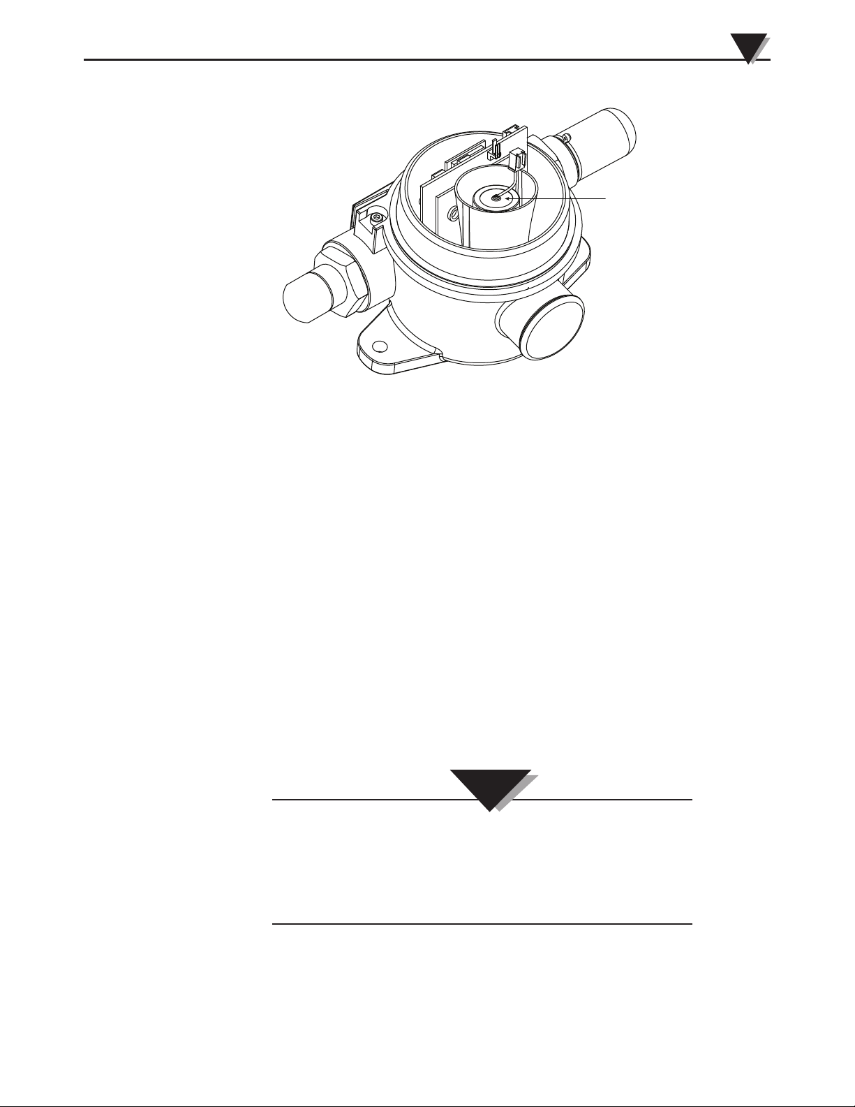
To install or replace the battery in your End Device you must first remove Lid of
the enclosure. This will allow you to access the battery compartment.
Page 19
Transmitter Setup & Installation
DEVICE BATTERY
Figure 3-13. Battery Replacement
3
Your End Device is equipped with a “C” size lithium power cell assembly.
Omega Part Number: UWTC-BATT-C. To install a replacement battery assembly
follow the steps outlined here.
A. Disconnect the battery from the main circuit board.
B. Remove the battery assembly from the housing.
C. Install your new battery assembly into the housing in the same position as the
old battery was located.
D. Connect the battery assembly connector to the mating connector on the top of
the main circuit board.
E. Installation complete.
Your transmitter is rated for use in ambient temperatures between -10°C (14°F)
to 70°C (158°F). Exposure to temperatures below or above these stated
temperatures can cause your device to malfunction and produce incorrect
operation. When installing your thermocouple probe care should be taken to
make sure your transmitter will not be operated in an environment outside the
specifications outlined in Section 7.
CAUTION:
Installing your end device in an application were the unit will
be exposed to ambient temperatures above or below the
operating limits specified in this manual will damage your
unit and cause the unit to malfunction and produce incorrect
operation.
3-11
Page 20

3
Transmitter Setup & Installation
WARNING:
Lithium batteries may get hot, explode or ignite and cause serious injury if exposed to abusive
conditions. Be sure to follow the safety warnings listed below:
Your transmitter operates with one 3.6V Lithium Battery. Omega Replacement Part Number UWTC-BAT-C.
Never operate your transmitter with a different battery than what is specified in this manual or on the
product data sheet.
Do not discharge the battery using any device except your Transmitter unit. When the battery is used
in devices other than the specified device, it may damage the battery or reduce its life expectancy. If
the device causes an abnormal current to flow, it may cause the battery to become hot, explode or
ignite and cause serious injury.
Refer to the Omega technical data sheet or this manual for the temperature ranges over which the
battery can be operated. Use of the battery outside this temperature range may damage the
Transmitter or reduce the performance and life of the battery.
• Do not place the battery in fire or heat the battery.
• Do not store batteries with other hazardous or combustible materials.
• Do not install the battery backwards so the polarity is reversed.
• Do not connect the positive terminal and negative terminal of the battery to each other with any
metal object (such as wire).
• Do not carry or store the battery together with metal objects.
• Do not pierce the battery with nails, strike the battery with a hammer, step on the battery or
otherwise subject it to strong impacts or shocks.
• Do not solder directly onto the battery.
• Do not expose battery to water or salt water, or allow the battery to get wet.
• Do not disassemble or modify the battery.
• When the battery is discharged, insulate the terminals with adhesive tape or similar materials before
disposal.
• Immediately discontinue use of the battery if, while using or storing the battery, the battery emits an
unusual smell, feels hot, changes color or shape, leaks or appears abnormal in any other way.
Contact Omega if any of these problems are observed.
• Do not place the battery in microwave ovens, high-pressure containers.
3-12
Page 21
Section 4 – System Operation
RECEIVER
4.1 Introduction
Compared to wired pH systems, wireless pH systems provide much simpler
installation. Based on the physical principle of the propagation of radio waves,
certain basic conditions should be observed. The following simple
recommendations are provided to insure proper installation and correct
operation of your wireless system.
4.2 RF Communication Basics
The Model UWXL-24-PH sends wireless transmissions to a receiver. The receiver
checks the incoming data for accuracy and processes this data for use by the
measurement software on your PC. Radio signals are electromagnetic waves,
hence the signal becomes weaker the further it travels. While radio waves can
penetrate some solid materials like a wall, they are dampened more than when a
direct line-of-sight between the transmitting and receiving antenna exist.
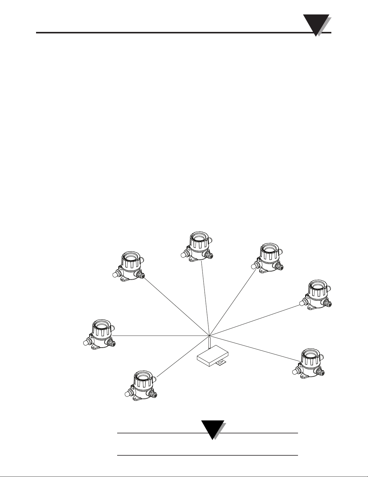
4.3 Basic System Overview
System Operation
4
The UWXL wireless pH system is comprised of only two main components; a
signal conditioner with a built-in battery powered 2.4GHz radio transmitter, and
a USB powered 2.4GHz radio receiver.
Figure 4-1. Basic System Overview
NOTE:
Up to 48 end devices can be used with one receiver.
4-1
Page 22
4
3
4
1
2
System Operation
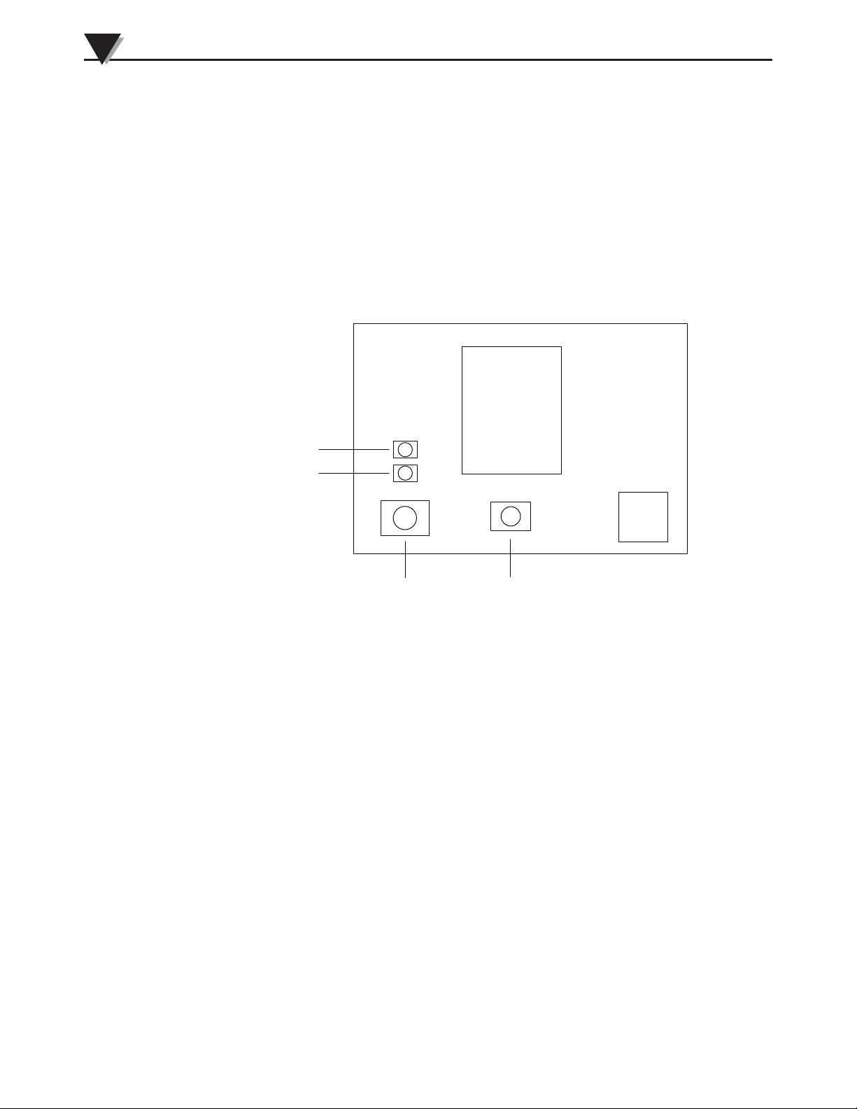
4.4 Connector/Transmitter Operation
4.4.1 Button Operation
(1.) ON/OFF
The ON/OFF button on the main circuit board of your transmitter is used to
turn your unit on or off.
(2.) SETUP
The SETUP button on the main circuit board of your transmitter is only used
during the setup and configuration of your unit. See Section 3.1.2 for more
information
Figure 4-2. UWXL Industrial Wireless Transmitter Button Options
(1) “SETUP” Button
(2) “ON/OFF” Button
(3) Transmit Indicator
(4) Battery Indicator
4.4.2 Indicator Lights
1) Transmit (TX) Green Indicator Light
The green indicator light marked “TX” on the front of the connector/transmitter
will blink every time the unit sends data to the receiving unit. Example; If you
selected a 5 sec sample rate the green TX led will blink one time every 5 seconds.
2) Low Battery (Low Bat) Red Indicator Light
The red indicator light marked “Low Bat” on the front of the transmitter will
turn on when the battery reaches a level at or below the power level required for
normal operation. When this indicator turns on it’s time to install a fresh battery
in your unit. For information on battery life see Section 6.11.
4-2
Page 23
4.5 Environment/Conditions
4.5.1 Environment
Omega’s wireless end devices and receiver units have been designed to be fixed
mounted and operated in a clean and dry indoor environment. Care should be
taken to prevent the components of your wireless system from being exposed to
moisture, toxic chemicals and extreme cold or hot temperature that are outside
the specifications listed in this manual.
4.5.2 Ambient Temperature Readings
The ambient temperature reading displayed on your screen when running the
TC-Central program, is the actual ambient temperature that your transmitter is
being exposed to. This reading is only provided as reference and to aid you in
proper installation of your unit. The ambient temperature reading will blink and
change to RED digits to alert you that the temperature has exceed the maximum
recommended safe operating limit for your transmitter. You should not rely on
this feature as sole protection. Additional protection should be taken the user to
protect your unit from extreme conditions.
NOTE:
System Operation
4
Operating your transmitter outside the specified ambient
conditions listed in Section 9 of this manual may cause your
unit to malfunction and stop working correctly.
4.5.3 Operating Conditions
The following is a list of basic good practice you should apply when operating
your wireless system.
• Never operate your wireless device or receiver outside the recommended
environmental limits specified in this manual.
• Never operate your wireless end device or receiver in flammable or explosive
environments.
• Never use your wireless end device or receiver in medical, nuclear or other
dangerous applications where an interruption of readings can cause
damage or harm.
• Never operate your end device or receiver with any other battery or power
source than what’s specified in this manual or on the battery compartment
label.
• No co-location with other radio transmitters is allowed. By definition, colocation is when another radio device or it’s antenna is located within 20 cm
of your end device and can transmit simultaneously with your end device.
• Never install end devices within 20 cm or less from each other.
• Never use your end device as a portable device. Your unit has been designed
to be operated in a permanent installation.
• Never install and/or operate your end device closer than 20 cm to nearby
persons.
• Never operate your end device with any other antenna than what is supplied
or listed here in this manual for approved use.
4-3
Page 24
4
CONTROL ROOM
MANUFACTURING AREA
MA NU FA CT URI NG A RE A
STORAGE ROOM
OFFICE
OFFICE
TRANSMITTER
RECEIVER
System Operation
4.6 Determining and Maximizing Range
The available maximum range specified for the wireless
Series system in this manual is only achievable under
optimum installation conditions. Mounting height, obstructions
in your “Fresnel Zone” and ambient conditions can cause a
decrease in signal strength resulting in a shorter range
between your transmitter and receiver unit.
The following recommendations will help to improve the range of your wireless
system.
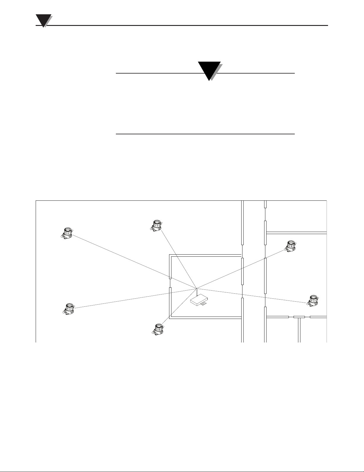
Position your receiver in a central location
When multiple transmitters are in operation, position your receiver unit in a
central space if possible in equal distance to each connector transmitter.
NOTE:
4-4
Figure 4-3. Determining Maximum Range
Test your system before permanent mounting
Before permanently mounting your transmitters in your application try moving
the devices to different locations and mounting angles to determine what
installation achieves the best signal strength.
Move your system components higher off the floor and away from exterior walls
Avoid installing your system components to close to the floor or near your
buildings exterior walls. The closer your transmitter and receiver unit are the
greater the interference and lose of signal strength will be.
Page 25

System Operation
Maintain a line of sight (LOS) between antennas
Maintaining a line of sight between your transmitter and receiver unit will
produce greatly improved signal strength over a system were the antenna’s in
your system have obstacles blocking them.
Maintain a constant ambient temperature environment
Maintaining a constant ambient temperature environment is important to
achieving maximum signal strength. Exposing your system components to
extreme hold or cold temperatures, or sudden changes in ambient conditions
will have an effect on the performance of your system.
4.6.1 Operation in Buildings
Your transmitter sends wireless data transmissions to a receiver connected to
your PC. Radio signals are electromagnetic waves. A radio signal becomes
weaker the further it travels. Range is decreased by different types of materials
found in the direction of the signals propagation. Radio waves can penetrate
most types of wall materials, but they are dampened more than they would be
by a direct line-of-sight installation.
4.6.2 Building Materials
4
Material Type Possible Signal Reduction
Wood, Plaster, Sheetrock, Uncoated 0 to 10%
Glass w/o Metal, Fiberglass
Brick, Pressboard 5 to 35%
Reinforced Concrete 10 to 90%
Metal Walls, Metal Doors, Elevators,
Metal Stair Cases, Metal Piping, 90 to 100%
Metal Mesh, Metal Screening
Figure 4-4 Operation In Buildings
Avoid dampening materials by repositioning the transmitting and/or receiver.
4.6.3. Penetration Angle of Radio Waves Through Walls
The angle at which the transmitted radio signal hits a wall is very important and
also has a big effect on maximizing range. Signals between your transmitter
should be transmitted as directly as possible.
4-5
Page 26
System Operation
4
4.7 Antenna Basics
4.7.1 Antenna Basics
By definition, an antenna is a device used to transform an RF signal, traveling on
a conductor, into an electromagnetic wave in free space. Antennas demonstrate a
property known as reciprocity, this means that an antenna will always maintain
the same characteristics regardless if it is used to transmit or receive. Most
antennas are resonant devices, which means they operate efficiently over a
relatively very narrow frequency band. An antenna must be tuned to the same
frequency band of the radio system to which it is connected, otherwise the
reception and the transmission will be impaired. The antennas in your wireless
transmitter system have been tuned to operate in the 2.4 GHz band.
NOTE:
In some cases, a short RF cable may be used to connect an
antenna to your device. Please note that RF extension cables
will always add some loss to the transmitting signal strength.
The longer the cable the more signal will be lost over that
cable. Because of this, the length of the cable should be kept
as short as possible.
4.8 Antenna Placement
Proper antenna installation is important and will allow you to achieve maximum
performance and range between your transmitter and receiver unit.
Your transmitter should not be installed on the same side of
the wall as the receiver. If mounted close to each other on the
same wall, the radio waves are likely to be subject to
interfering dispersions or reflections. The best positioning is to
have the transmitter installed on the opposite or connecting
NOTE:
4-6
Page 27
System Operation
R
ANTENNA
USB
I/O
9–24 Vdc
OMEGA ENGINEERING, INC.
Stamford, CT 06907
UWTC SERIES
WIRELESS RF RECEIVER
2.4 GHz
omega.com
Made in U.S.A.
-
+
!
TX
RX
SB
PWR
This device complies with Part 15 of the FCC rules.
Operation is subject to the following two conditions:
1) This device may not cause harmful interference;
2) This device must accept any interference received,
including interference that may cause undesired
operation.
FCC ID: OUR–XBEEPRO
IC #4214A–XBEEPRO
F
®
R
ANTENNA
USB
I/O
9–24 Vdc
OMEGA ENGINEERING, INC.
Stamford, CT 06907
UWTC SERIES
WIRELESS RF RECEIVER
2.4 GHz
omega.com
Made in U.S.A.
-
+
!
TX
RX
SB
PWR
This device complies with Part 15 of the FCC rules.
Operation is subject to the following two conditions:
1) This device may not cause harmful interference;
2) This device must accept any interference received,
including interference that may cause undesired
operation.
FCC ID: OUR–XBEEPRO
IC #4214A–XBEEPRO
F
®
4
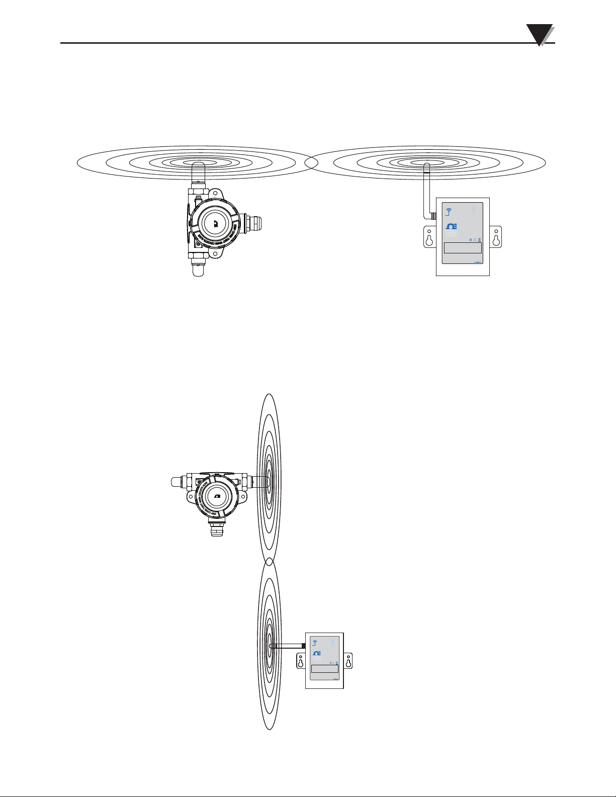
If your transmitter is mounted in a horizontal position in your application you
should mount your receiving so that the same polarization is achieved with the
receiving antenna. As shown in the “Horizontal” example above.
4.8.1 Horizontal Antenna Placement
Figure 4-5. Horizontal Antenna Placement
4.8.2 Vertical Antenna Placement
If your transmitter is mounded in a vertical position in your application you
should mount your receiving so that the same polarization is achieved with the
receiving antenna. As shown in the “Vertical” example Fig 4-6.
Figure 4-6. Vertical Antenna Placemen
4-7
Page 28

System Operation
4
4.9 Factory Preset Values
Your transmitter has been factory programmed for the following default
operation; Channel Number: 1, Transmit Rate: 1 sample/5 sec
4.10 Transmit Rate vs. Battery Life
Many factors such as ambient temperature and transmission rate can have a
major affect on the life of the battery used in your transmitter. The transmit rate
is the biggest factor in the life of your battery. The longer the transmit rate you
set, the longer the battery in your device will last. The table below give some
estimates on how long the battery should last for the transmit rate you selected
when you setup your transmitters if used under normal operating conditions.
For Model UWXL-24-PH
Transmit Time Estimated Battery Life
1 Sample/2 Seconds 30 days
1 Sample/3 Seconds 45 days
1 Sample/5 Seconds 75 days
1 Sample/10 Seconds 150 days
1 Sample/15 Seconds 225 days
1 Sample/30 Seconds 450 days
1 Sample/45 Seconds 675 days
1 Sample/60 Seconds 912 days
4-8
Page 29

Section 5 – Troubleshooting
The information provided in this section should solve most of the common
problems you may experience when installing or operating your wireless
System. If the problems and solutions outlined here do not solve your problem,
please contact Omega’s customer service department. Contact information can
be found in Section 2 of this manual or by visiting omega.com.
5.1 Transmitter Troubleshooting
Problem Solution
1. Unit will not enter “Setup” mode a.Check USB cable connection
2. Configuration Utility will not connect a. Check USB cable connection to
Troubleshooting
b. Contact Customer Service
device being programmed
b. Confirm you are in the
“SETUP”mode. See Section 3
c. Contact Customer Service
5
5.2 Receiver Troubleshooting
Problem Solution
1. Unit will not turn on a. Check power cord connections
b. Unit requires service, contact
Customer Service
5-1
Page 30

6
Service and Calibration
Section 6 – Service & Calibration
6.1 Calibration
Your UWXL-24-PH Wireless pH/Temp Transmitter has been factory calibrated
for a pH range of 2 to 12 and a temperature range of 0 to 100°C. Information is
provided below on how to perform a field calibration of your unit for custom pH
and temperature ranges.
For pH there are 2 options available, a 1 point offset calibration and a more
accurate 2 point calibration. The pH calibration performs a temperature
correction based on the RTD reading. If you are not using and RTD you must
connect a 110 Ohm resistor across the RTD input and maintain the buffer
solution temperature as close to 25°C as possible. If you cannot maintain the
buffer solution at 25°C, a different resistor value can be used that corresponds to
the RTD resistance of the solution temperature in degrees Celsius.
To calibrate your transmitter, connect it to your PC using the USB cable and start
the End Device Configuration Wizard. Follow the steps until you reach step 6.
At step 6 select the calibration option you wish to perform. Follow the onscreen
instructions for the calibration. For the 2 point calibration any 2 points can be
used. The 1 point pH offset calibration, although not as accurate as the two point
method, is useful in cases where the UWPH and/or probe are permanently
mounted in a hard to reach area, such as in a sump for effluent (waste water)
monitoring. The 2 point RTD probe calibration can be done at any two points
between 0 and 100°C. In the case where temperature calibrator is not available, 0
and 100°C are the best points because you can use melting ice and boiling water
to obtain accurate results.
6.2 Service
If any of your wireless system components require service, please call our
Customer Service Department at 1-800-622-2378 or 203-359-1660. They will assist
you in arranging the return of your device. We can also be reached on the
Internet at www.omega.com, e-mail: [email protected]
6-1
Page 31

Section 7 – Specifications
Computer Interface: USB
Transmit Sample Rate: Programmable from 2 sec to 120 sec
Radio Frequency (RF)
Transceiver Carrier: ISM 2.4 GHz, direct sequence spread
RF Output Power: 18 dBm (63 mW)
Range of RF Link: Up to 450 m (1500 ft) outdoor line of sight;
RF Data Packet Standard: EEE 802.15.4, open communication
Power: One 3.6V, Lithium C Cell (included)
Battery Life (Typical): 3 years; at 1 sample/minute reading rate
pH Input
Input Range: 0 to 14 pH
Specifications
spectrum, (2.450 to 2.490 GHz - 12 RF
channels)
up to 90 m (300 ft) indoor/urban
architecture
@ 25°C
7
Accuracy: ±0.1 pH
Resolution: 0.01 pH
Response Time: 2 sec max
Input Connection: BNC connector
Input Impedance: 1012 ohms, Typical
Temperature Compensation: Automatic, 0 to 100°C (32 to 212°F)
RTD Temperature Input
Input Type: Pt100 , European curve (0.00385)
Range: 0 to 100°C (32 to 212°F)
Accuracy: ±1°C (1.8°F)
Resolution: 0.1°C or °F
Input Connection: M12 connector; mating connector (included)
Computer Interface: USB
Transmit Sample Rate: Programmable from 1 per minute to 30 per
min (1 per 2 sec)
Radio Frequency (RF) Transceiver
Carrier: ISM 2.4 GHz, direct sequence spread spectrum
RF Output Power: 18 dBm (63 mW)
Range of RF Link
Outdoor Line of Sight: Up to 120 m (400')
Indoor/ Urban: Up to 40 m (130')
7-1
Page 32

7
Specifications
RF Data Packet Standard: IEEE 802.15.4, open communication
Software (Included Free): Requires Windows
Power: One 3.6V, lithium “C” cell (included)
Battery Life (Typical): 3 years; 1 sample/minute reading rate @ 25°C
Enclosure: IP68 Industrial enclosure
Enclosure Dimensions: 125 W x 105.5 L x 110 D
Note: pH and RTD probes sold separately
architecture
®
2000, XP or Vista (32 bit)
operating system
(4.92" W x 4.15"L x 4.33" D)
8-1
Page 33
All approvals outlined in this manual are based on testing
that was done with antennas that are supplied with your
Wireless Series System Components. Removing and or
installing a different antenna will void the product compliance
demonstrated in these documents.
8.1 FCC (Domestic Use)
For United States: FCC ID: OUR-XBEEPRO
For Canada: IC #4214A-EXBEEPRO
This device complies with Part 15 of the FCC rules. Operation is subject to the
following two conditions: 1.) This device may not cause harmful interference.
2.) This device must accept any interference received, including interference that
may cause undesired operation.
Approvals, Regulatory Compliance
NOTE:
WARNING:
8
To satisfy FCC RF exposure requirements for mobile
transmitting devices, a separation distance of 20 cm or more
should be maintained between the antenna of this device and
persons during device operation. To ensure compliance,
operations at closer than this distance is not recommended.
The antenna used for this transmitter must not be co-located
in conjunction with any other antenna or transmitter.
8-2
Page 34

NOTES:
8-2
Page 35

WARRANTY/DISCLAIMER
OMEGA ENGINEERING, INC. warrants this unit to be free of defects in materials and workmanship for a
period of 13 months from date of purchase. OMEGA’s WARRANTY adds an additional one (1) month
grace period to the normal one (1) year product warranty to cover handling and shipping time. This
ensures that OMEGA’s customers receive maximum coverage on each product.
If the unit malfunctions, it must be returned to the factory for evaluation. OMEGA’s Customer Service
Department will issue an Authorized Return (AR) number immediately upon phone or written request.
Upon examination by OMEGA, if the unit is found to be defective, it will be repaired or replaced at no
charge. OMEGA’s WARRANTY does not apply to defects resulting from any action of the purchaser,
including but not limited to mishandling, improper interfacing, operation outside of design limits,
improper repair, or unauthorized modification. This WARRANTY is VOID if the unit shows evidence of
having been tampered with or shows evidence of having been damaged as a result of excessive corrosion;
or current, heat, moisture or vibration; improper specification; misapplication; misuse or other operating
conditions outside of OMEGA’s control. Components in which wear is not warranted, include but are not
limited to contact points, fuses, and triacs.
OMEGA is pleased to offer suggestions on the use of its various products. However,
OMEGA neither assumes responsibility for any omissions or errors nor assumes liability for any
damages that result from the use of its products in accordance with information provided by
OMEGA, either verbal or written. OMEGA warrants only that the parts manufactured by the
company will be as specified and free of defects. OMEGA MAKES NO OTHER WARRANTIES OR
REPRESENTATIONS OF ANY KIND WHATSOEVER, EXPRESSED OR IMPLIED, EXCEPT THAT OF
TITLE, AND ALL IMPLIED WARRANTIES INCLUDING ANY WARRANTY OF MERCHANTABILITY
AND FITNESS FOR A PARTICULAR PURPOSE ARE HEREBY DISCLAIMED. LIMITATION OF
LIABILITY: The remedies of purchaser set forth herein are exclusive, and the total liability of
OMEGA with respect to this order, whether based on contract, warranty, negligence,
indemnification, strict liability or otherwise, shall not exceed the purchase price of the
co mponent upon which liability is based. In no even t shall OMEGA be liable for
consequential, incidental or special damages.
CONDITIONS: Equipment sold by OMEGA is not intended to be used, nor shall it be used: (1) as a “Basic
Component” under 10 CFR 21 (NRC), used in or with any nuclear installation or activity; or (2) in medical
applications or used on humans. Should any Product(s) be used in or with any nuclear installation or
activity, medical application, used on humans, or misused in any way, OMEGA assumes no responsibility
as set forth in our basic WARRANTY/DISCLAIMER language, and, additionally, purchaser will indemnify
OMEGA and hold OMEGA harmless from any liability or damage whatsoever arising out of the use of the
Product(s) in such a manner.
RETURN REQUESTS/INQUIRIES
Direct all warranty and repair requests/inquiries to the OMEGA Customer Service Department. BEFORE
RETURNING ANY PRODUCT(S) TO OMEGA, PURCHASER MUST OBTAIN AN AUTHORIZED RETURN
(AR) N U MB ER F R OM OMEGA’ S C U ST OMER SERVI CE D E PART ME NT ( IN O R DER TO AVOI D
PROCESSING DELAYS). The assigned AR number should then be marked on the outside of the return
package and on any correspondence.
The purchaser is responsible for shipping charges, freight, insurance and proper packaging to prevent
breakage in transit.
FOR WARRANTY
following information available BEFORE
contacting OMEGA:
1. Purchase Order number under which the product
was PURCHASED,
2. Model and serial number of the product under
warranty, and
3. Repair instructions and/or specific problems
relative to the product.
OMEGA’s policy is to make running changes, not model changes, whenever an improvement is possible. This affords
our customers the latest in technology and engineering.
OMEGA is a registered trademark of OMEGA ENGINEERING, INC.
© Copyright 2012 OMEGA ENGINEERING, INC. All rights reserved. This document may not be copied, photocopied,
reproduced, translated, or reduced to any electronic medium or machine-readable form, in whole or in part, without the
prior written consent of OMEGA ENGINEERING, INC.
RETURNS, please have the
FOR NON-WARRANTY REPAIRS,
for current repair charges. Have the following
information available BEFORE contacting OMEGA:
1. Purchase Order number to cover the COST
of the repair,
2. Model and serial number of the product, and
3. Repair instructions and/or specific problems
relative to the product.
consult OMEGA
Page 36

Where Do I Find Everything I Need for
Process Measurement and Control?
OMEGA…Of Course!
Shop online at omega.com
SM
TEMPERATURE
䡺⻬
Thermocouple, RTD & Thermistor Probes, Connectors, Panels & Assemblies
䡺⻬
Wire: Thermocouple, RTD & Thermistor
䡺⻬
Calibrators & Ice Point References
䡺⻬
Recorders, Controllers & Process Monitors
䡺⻬
Infrared Pyrometers
PRESSURE, STRAIN AND FORCE
䡺⻬
Transducers & Strain Gages
䡺⻬
Load Cells & Pressure Gages
䡺⻬
Displacement Transducers
䡺⻬
Instrumentation & Accessories
FLOW/LEVEL
䡺⻬
Rotameters, Gas Mass Flowmeters & Flow Computers
䡺⻬
Air Velocity Indicators
䡺⻬
Turbine/Paddlewheel Systems
䡺⻬
Totalizers & Batch Controllers
pH/CONDUCTIVITY
䡺⻬
pH Electrodes, Testers & Accessories
䡺⻬
Benchtop/Laboratory Meters
䡺⻬
Controllers, Calibrators, Simulators & Pumps
䡺⻬
Industrial pH & Conductivity Equipment
DATA ACQUISITION
䡺⻬
Data Acquisition & Engineering Software
䡺⻬
Communications-Based Acquisition Systems
䡺⻬
Plug-in Cards for Apple, IBM & Compatibles
䡺⻬
Data Logging Systems
䡺⻬
Recorders, Printers & Plotters
HEATERS
䡺⻬
Heating Cable
䡺⻬
Cartridge & Strip Heaters
䡺⻬
Immersion & Band Heaters
䡺⻬
Flexible Heaters
䡺⻬
Laboratory Heaters
ENVIRONMENTAL
MONITORING AND CONTROL
䡺⻬
Metering & Control Instrumentation
䡺⻬
Refractometers
䡺⻬
Pumps & Tubing
䡺⻬
Air, Soil & Water Monitors
䡺⻬
Industrial Water & Wastewater Treatment
䡺⻬
pH, Conductivity & Dissolved Oxygen Instruments
M4835-PH/0313
 Loading...