

Page 1
omega.com
e-mail: [email protected]
For latest product manuals:
omegamanual.info
User’s Guide
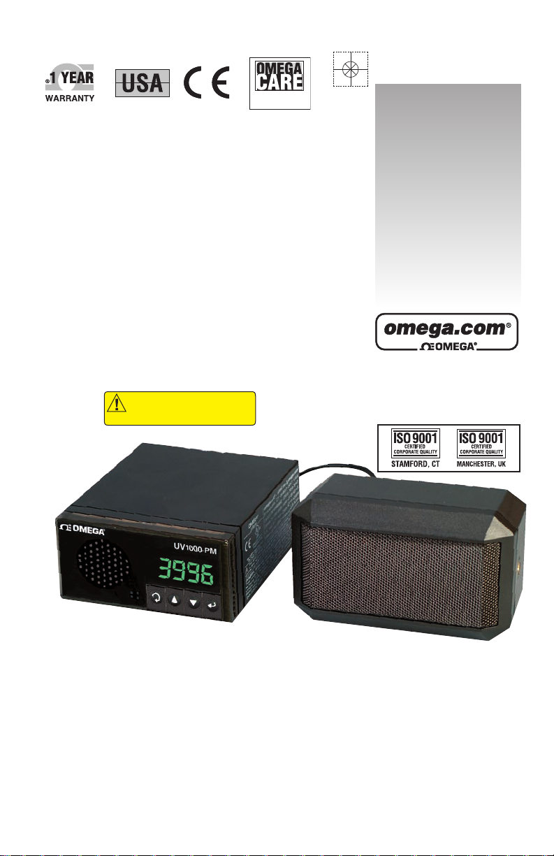
UV1000-PM
OMEGASEZ
®
Programmable
Universal Verbalizer
Panel Meter–
1
⁄8 DIN
MADE IN
Shop online at
SM
CAUTION!
is not intended for medical
use or use on humans
– This product
Extended Warranty
Program
Page 2

Servicing North America:
U.S.A.: Omega Engineering, Inc., One Omega Drive, P.O. Box 4047
ISO 9001 Certified
Stamford, CT 06907-0047
Toll-Free: 1-800-826-6342 Tel: (203) 359-1660
FAX: (203) 359-7700 e-mail: [email protected]
Canada: 976 Bergar
Laval (Quebec), Canada H7L 5A1
Toll-Free: 1-800-826-6342 TEL: (514) 856-6928
FAX: (514) 856-6886 e-mail: [email protected]
For immediate technical or application assistance:
U.S.A. and Canada: Sales Service: 1-800-826-6342/1-800-TC-OMEGA
®
Customer Service: 1-800-622-2378/1-800-622-BEST
®
Engineering Service: 1-800-872-9436/1-800-USA-WHEN
®
Mexico: En Español: 001 (203) 359-7803 FAX: (001) 203-359-7807
Servicing Europe:
Benelux: Managed by the United Kingdom Office
Czech Republic: Frystatska 184
733 01 Karviná, Czech Republic
Toll-Free: 0800-1-66342 TEL: +420-59-6311899
FAX: +420-59-6311114 e-mail: [email protected]
France: Managed by the United Kingdom Office
Toll-Free: 0800 466 342 TEL: +33 (0) 161 37 29 00
FAX: +33 (0) 130 57 54 27 e-mail: [email protected]
Germany/Austria: Daimlerstrasse 26
D-75392 Deckenpfronn, Germany
Toll-Free: 0 800 6397678 TEL: +49 (0) 7059 9398-0
FAX: +49 (0) 7056 9398-29 e-mail: [email protected]
United Kingdom: OMEGA Engineering Ltd.
ISO 9001 Certified
One Omega Drive, River Bend Technology Centre, Northbank
Irlam, Manchester M44 5BD England
Toll-Free: 0800-488-488 TEL: +44 (0)161 777-6611
FAX: +44 (0)161 777-6622 e-mail: [email protected]
OMEGAnet®Online Service Internet e-mail
omega.com [email protected]
It is the policy of OMEGA Engineering, Inc. to comply with all worldwide safety and EMC/EMI
regulations that apply. OMEGA is constantly pursuing certification of its products to the European New
Approach Directives. OMEGA will add the CE mark to every appropriate device upon certification.
The information contained in this document is believed to be correct, but OMEGA accepts no liability for any
errors it contains, and reserves the right to alter specifications without notice.
WARNING: These products are not designed for use in, and should not be used for, human applications.
Page 3

Table of Contents
Section Page
Section 1 Introduction ....................................................................... 1-1
1.1 Safety Considerations .......................................................... 1-2
1.2 Before You Begin .................................................................. 1-3
Section 2 Setup .................................................................................... 2-1
2.1 Front Panel ............................................................................ 2-1
2.2 Rear Panel Connections .............................................. 2-1/2-2
2.3 Power Connections .............................................................. 2-2
2.3.1 Thermocouple Input ..................................................... 2-3
2.3.2 Process Voltage Input ................................................... 2-3
2.3.3 Process Current Input................................................... 2-4
2.3.4 Wiring Relay Outputs................................................... 2-4
2.3.5 Wiring RS232 Output.................................................... 2-5
2.3.6 Wiring External Loud Speaker .................................... 2-6
2.4 Panel Mounting, Panel Cutout, Overall Dimensions....2-6/2-7
Section 3 Front Panel Button Operation ........................................ 3-1
3.1 MODE Button - Change the Input Selections .................. 3-1
3.2 Up and Down Buttons ........................................................ 3-1
3.3 Talk/Set Buttons .................................................................. 3-1
Section 4 Verbaview™ - User Configuration Software .............. 4-1
4.1 Verbaview™ Installation .................................................... 4-1
4.2 Starting the Verbaview™ Program ................................... 4-1
4.3 Settings Tag .......................................................................... 4-1
4.3.1 Select the COM Port ....................................................4-2
4.3.2 Check the "Skip Logo Sound".................................... 4-2
4.3.3 Talking Interval .......................................................... 4-2
4.3.4 Factory Default Settings Button ............................... 4-2
4.3.5 Calibration Mode..........................................................4-2
4.4 Calibrate Tag ........................................................................ 4-3
4.5 Input Tag .............................................................................. 4-3
4.5.1 Select the Input Type ................................................. 4-4
4.5.2 Select the Engineering Unit ....................................... 4-6
4.5.3 Select the Decimal Point ............................................ 4-7
4.5.4 Alarms Settings ........................................................... 4-7
4.5.5 Scaling (Voltage and Current Input Only) ..............4-8
4.5.6 TC Setup (Thermocouple Input Only) .................... 4-8
4.5.7 Voltage Range ...............................................................4-9
4.5.8 Current Range ............................................................. 4-9
4.5.9 Scaling the Engineering Unit
(Voltage and Current Input Only) .............................4-9
i
UV1000-PM Programmable Universal Verbalizer
Page 4

Table of Contents
4.5.10 The Set and Read buttons . . . . . . . . . . . . . . . . . . . . 4-9
4.5.11 Application Examples
of Rescaling the Engineering Unit . . . . . . . . . . . . . . . . . 4-10
4.5.11.1 Voltage input settings and rescaling . . . . . . . . . 4-10
Application Example 1:
General Purpose Output Pressure Transducer . . . . . . . 4-10
Application Example 2:
High Temperature Handheld Infrared Thermometer . 4-12
4.5.11.2
0 to 20 mA Current Input Settings and Rescaling
. .4-15
Application Example 3:
Miniature Low Cost Non-Contact
IR Temperature Sensor/Transmitter . . . . . . . . . . . . . . . 4-15
Application Example 4:
Liquid Flow Transmitters . . . . . . . . . . . . . . . . . . . . . . . . . 4-18
4.6 Load/Save Tag . . . . . . . . . . . . . . . . . . . . . . . . . . . . . . . . . .4-21
4.7 Error Messages . . . . . . . . . . . . . . . . . . . . . . . . . . . . . . . . . .4-22
Section 5 Specifications Software . . . . . . . . . . . . . . . . . . . . . . . . . .5-1
Appendix 1 Factory Default Settings . . . . . . . . . . . . . . . . . . . .5-2
Appendix 2 Engineering Units Table . . . . . . . . . . . . . .5-3 to 5-7
ii
UV1000-PM Programmable Universal Verbalizer
Page 5
UV1000-PM Programmable Universal Verbalizer
iii
NOTES, WARNINGS and CAUTIONS
Information that is especially important to note is identified by following labels:
• NOTE
• WARNING or CAUTION
• IMPORTANT
• TIP
NOTE: Provides you with information that is important to successfully
setup and use the Programmable Digital Meter.
CAUTION or WARNING: Tells you about the risk of electrical shock.
CAUTION, WARNING or IMPORTANT: Tells you of circumstances or
practices that can effect the instrument’s functionality and must refer
to accompanying documents.
TIP: Provides you helpful hints.
Page 6

Section 1 - Introduction
The UV1000-PM universal verbalizer panel meter is an innovative
panel meter that can verbalize and display process signals. It can accept
0 to 10 Vdc voltage input, 0 to 20 mA or 4 to 20 mA current input, and
Type J, K, T, and R thermocouple input signals.
You can easily configure and program the verbalizer through the
friendly PC user interface - to specify the input range, display decimal
point, analog input scaling, select audible engineering unit, high/low
alarm set point, alarm deadband and etc. Select from over 100 audible
engineering units while you are configuring the verbalizer. The front
buttons allows the user to select different inputs, switch between
command/continuous talk, and adjusting volumes. The UV1000-PM is
a creative solution for you to monitor almost any type of your sensor
measurement value in speech/ display/alarming format.
The Universal Verbalizer UV1000-PM is not designed to measure high
voltage or current signals. It is designed to measure up to 10 Vdc max.
voltage and 20 mA max. current signals.
1-1
UV1000-PM Programmable Universal Verbalizer
1
Page 7
This device is marked with the international caution symbol. It is important
to read this manual before installing or commissioning this device as it
contains important information relating to Safety and EMC
(Electromagnetic Compatibility).
Installation of this instrument should be done by qualified personnel. In order
to ensure safe operation, the following instructions should be followed.
This instrument has no power-on switch. An external switch or circuitbreaker shall be included in the building installation as a disconnecting
device. It shall be marked to indicate this function, and it shall be in close
proximity to the equipment within easy reach of the operator. The switch or
circuit-breaker shall meet the relevant requirements of IEC 947–1 and
IEC 947-3 (International Electrotechnical Commission). The switch shall
not be incorporated in the main supply cord.
Furthermore, to provide protection against excessive energy being drawn
from the main supply in case of a fault in the equipment, an overcurrent
protection device shall be installed.
• Do not exceed voltage rating on the label located on the top of the
instrument housing.
• Always disconnect power before changing signal and power
connections.
• Do not use this instrument on a work bench without its case for safety
reasons.
• Do not operate this instrument in flammable or explosive atmospheres.
• Do not expose this instrument to rain or moisture.
• Unit mounting should allow for adequate ventilation to ensure
instrument does not exceed operating temperature rating.
• Use electrical wires with adequate size to handle mechanical strain
and power requirements. Install without exposing bare wire outside the
connector to minimize electrical shock hazards.
EMC Considerations
• Whenever EMC is an issue, always use shielded cables.
• Never run signal and power wires in the same conduit.
• Use signal wire connections with twisted-pair cables.
• Install Ferrite Bead(s) on signal wires close to the instrument if EMC
problems persist.
Failure to follow all instructions and warnings may result in injury!
1-2
1
UV1000-PM Programmable Universal Verbalizer
1.1 Safety Considerations
Page 8

1.2 Before You Begin
Inspecting Your Shipment:
Remove the packing slip and verify that you have received everything
listed. Inspect the container and equipment for signs of damage as soon
as you receive the shipment. Note any evidence of rough handling in
transit. Immediately report any damage to the shipping agent. The
carrier will not honor damage claims unless all shipping material is
saved for inspection. After examining and removing the contents, save
the packing material and carton in the event reshipment is necessary.
Customer Service:
If you need assistance, please call the nearest Customer Service
Department, listed in this manual.
Manuals, Software:
The latest Operation and Communication Manual as well as free
configuration software is available from the website listed in this
manual or on the CD-ROM enclosed with your shipment.
External Speaker:
External louder speaker is included as an accessory.
1-3
UV1000-PM Programmable Universal Verbalizer
1
Page 9
Section 2 – Setup
2.1 Front Panel
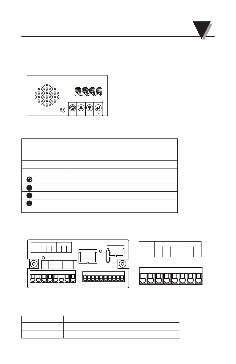
Figure 2.1 Front panel display
TC Thermocouple input indicator
V Voltage input indicator
I Current input indicator
C Not in use
AL Alarm indicator
MODE Change the input selection
UP Turn the volume up
DOWN Turn the volume down
TALK/SET Press to talk, or switch between
command talk and continuous talk
▲
▼
▼
▼
2.2 Rear Panel Connections
The rear panel connections are shown in Figures 2.2 and 2.3.
Figure 2.2 Rear Panel View, Power and Output Connections
POWER AC/DC Power Connector: All models
OUTPUT 1 Relay SPDT
OUTPUT 2 Relay SPDT
Table 2.2 Rear Panel Power and Output Connector
Table 2.1 Front Panel Annunciators
MODE
DOWN
UP
SET
TALK
UV1000-PM
V
TC
I
C
AL
C
C
NC
NO
OUTPUT 2
NC
1
1
4
5
3
2
POWER
NO
876
L(+)
N(-)
OUTPUT 1
1
SP(-)
SP(+)
TC(-)
TC(+)
RTN
V
I
RTN
Rx
Tx
86910
2
3
5
4
7
8
4
21365
7109
6
7
8
3
4
5
1
2
2-1
2
UV1000-PM Programmable Universal Verbalizer
C
C
NC
NO
OUTPUT 2
NC
1
4
5
3
2
POWER
NO
876
L(+)
N(-)
OUTPUT 1
6
7
8
3
4
5
1
2
Page 10
The Safety European Standard EN61010-1 for measurement, control,
and laboratory equipment requires that fuses must be specified based on
IEC127. This standard specifies for a Time-lag fuse, the letter code “T”.
The above recommended fuses are of the type IEC127-2-sheet III. Be
aware that there are significant differences between the requirements
listed in the UL 248-14/CSA 248.14 and the IEC 127 fuse standards. As a
result, no single fuse can carry all approval listings. A 1.0 Amp IEC fuse
is approximately equivalent to a 1.4 Amp UL/CSA fuse. It is advised to
consult the manufacturer’s data sheets for a cross-reference.
SPEAKER
INPUT RS232
Tx
Rx
RTN
I
V
RTN
TC(+)
TC(–)
SP(+)
SP(–)
Figure 2.3 Rear Panel Input Connections
External Speaker Output Connect to provide external speaker
TC Input Thermocouple Input
Voltage Input 0 to 10 vdc Voltage Input
Current Input 0 to 20 mA or 4 to 20 mA Current Input
RS232 RS232 Serial Communication
2.2 Rear Panel Connections (Continued)
The rear panel connections are shown in Figures 2.2 and 2.3.
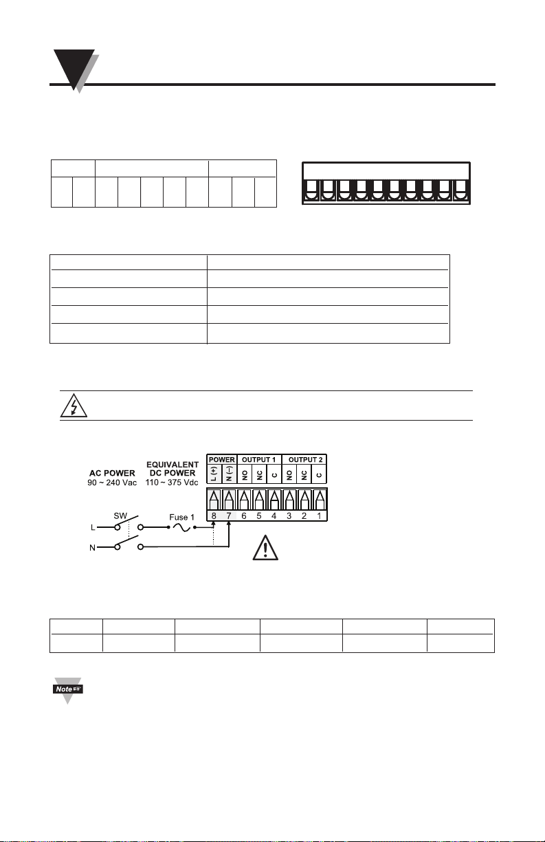
2.3 Power Connections
Caution: Do not connect power to your device until you have completed all
input and output connections. Failure to do so may result in injury!
FUSE Connector Output Type For 115 Vac For 230 Vac DC
FUSE1 POWER N/A 100 mA(T) 100 mA(T) 100 mA(T)
Use copper conductors
only for power connections
Connect the main power connection as shown in Figure 2.4
Figure 2.4 Main Power Connections
Table 2.3 Rear Panel Input/Output Connector
Table 2.4 Fuse Requirement (see specification)
2-2
UV1000-PM Programmable Universal Verbalizer
2
8
4
21365
7109
Page 11
2.3.1 Thermocouple Input
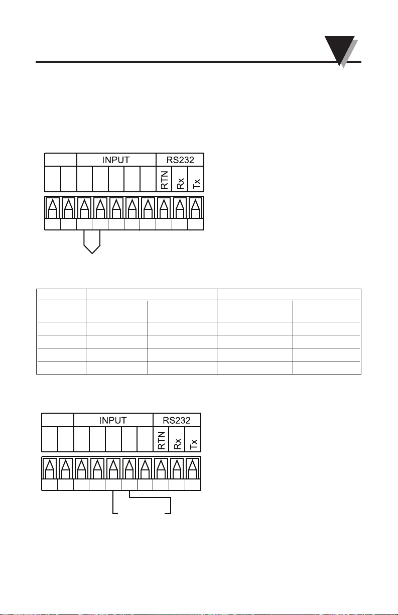
The figure below shows the wiring hookup for any thermocouple type.
For example, for Type K hookup, connect the yellow wire to the
"4" terminal - TC(+) and the red wire to the "3" terminal – TC(-).
When configuring your Verbalizer, select Thermocouple and Thermocouple
Type in the Input Type menu (see Part 3 and Part 4.5.6 TC Setup).
123456789
10
SP(-)
SP(+)
TC(-)
TC(+)
RTN
V
I
–
+
Figure 2.5 Thermocouple Wiring Hookup
TYPE Input Connector Jacket (External Insulation)
Terminal 3 Terminal 4 Extension Grade
TC (-) TC(+)
J Red White Dark-Brown Black
K Red Yellow Dark-Brown Yellow
T Red Blue Dark-Brown Blue
R Red Black - Green
Table 2.5 TC Wire Color Chart
123456789
10
SP(-)
SP(+)
TC(-)
TC(+)
RTN
V
I
0-10 Vdc
2.3.2 Process Voltage Input
The figure below shows the wiring hookup for Process Voltage 0–10 Vdc.
Figure 2.6 Process Voltage Wiring Hookup Without Sensor Excitation
When configuring your instrument, select Process Voltage Type in the
Input Type Menu.
2-3
2
UV1000-PM Programmable Universal Verbalizer
Page 12
123456789
10
SP(-)
SP(+)
TC(-)
TC(+)
RTN
V
I
0 ~20 mA
External Excitation
–
+
+
–
When configuring your instrument, select Current Type in the Input Type Menu.
2.3.4 Wiring Relay Outputs
Relay outputs OUTPUT1 and OUTPUT2 for High alarm and Low alarm
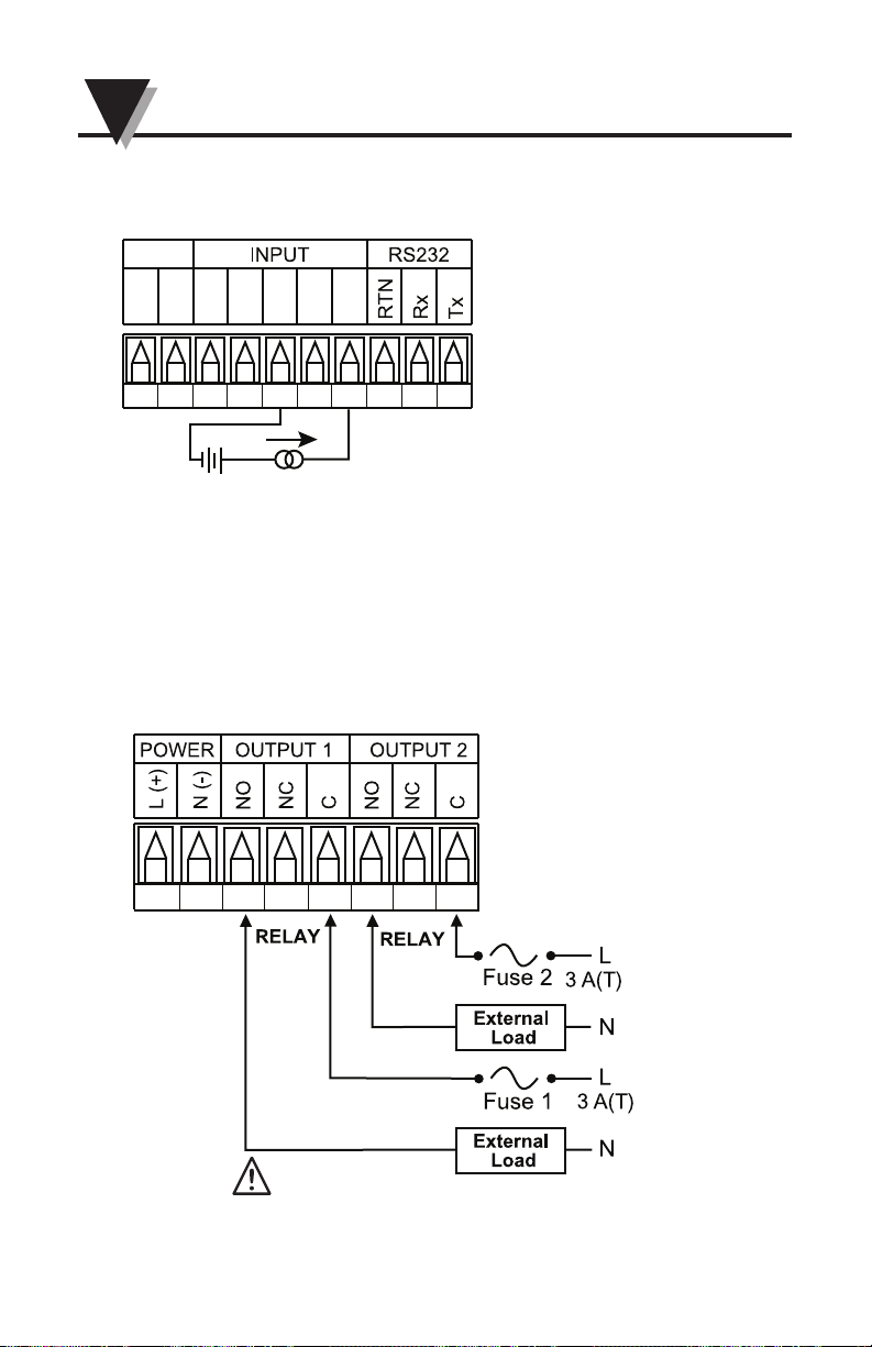
This meter has two factory installed outputs. The OUTPUT 1 is for high
alarm and OUTPUT 2 is for low alarm. The two SPDT Mechanical Relays
are shown below.
2.3.3 Process Current Input
The figure below shows the wiring hookup for Process Current 0 – 20 mA.
Figure 2.7 Process Current Wiring Hookup
(External Excitation)
87654321
Figure 2.8 Mechanical Relay Outputs Wiring Hookup
Use copper conductors
only for power connections
2-4
UV1000-PM Programmable Universal Verbalizer
2
Page 13
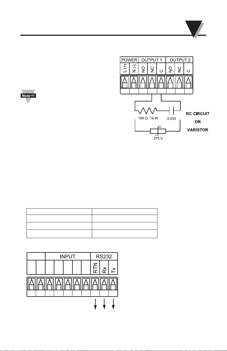
Figure 2.10 RS232 Output Wiring Hookup
This device has snubber circuits
designed to protect the contacts
of the mechanical relays when it
switches to inductive loads
(i.e. solenoids, relays). These
snubbers are internally connected
between the Common (C) and
Normally Open (NO) relay contacts of Output 1 and Output 2.
If you have an inductive load
connected between Common (C)
and Normally Closed (NC) contacts of the mechanical relays and
you want to protect them from the
rush current during the switching
period, you have to connect an
external snubber circuit between
Common (C) and Normally
Closed (NC) contacts as indicated
in Figure 2.9.
87654321
2.3.5 Wiring RS232 Output
RS232 output
This device has a programmable communication output. The
RS232 output connections are shown below.
123456789
10
SP(-)
SP(+)
TC(-)
TC(+)
RTN
V
I
RTN
Rx
Tx
RS232
Figure 2.9 Snubber Circuit Wiring
Hookup
2-5
2
UV1000-PM Programmable Universal Verbalizer
UV1000-PM RS232 DB-9 connector
8–RTN 5–GND
9–RX 3–TxD
10–Tx 2–RxD
Table 2.6 RS232 wiring to a computer DB-9 connector
Page 14
2-6
2.3.6 Wiring External Louder Speaker
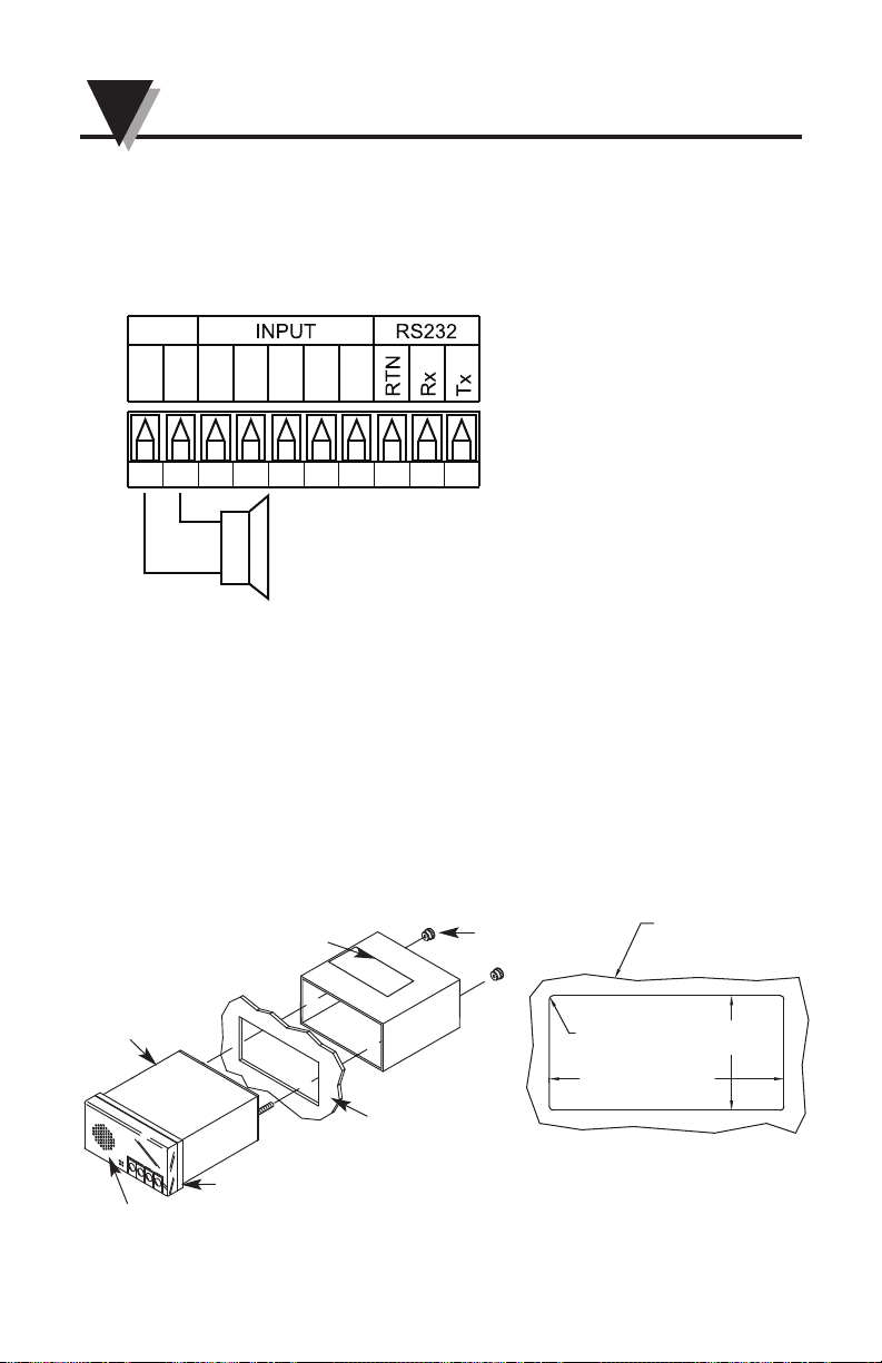
External Loudspeaker Output
This device has an external speaker output. The external loudspeaker
output wiring connections are shown below
123456789
10
SP(-)
SP(+)
TC(-)
TC(+)
RTN
V
I
–
+
Loudspeaker
Figure 2.11 External Speaker Output Wiring Hookup
2.4 Panel Mounting, Panel Cutout, Overall Dimensions
PANEL THICKNESS:
0.25 [6.4] MAX
0.03 [0.8] MIN
[45.00 +0.61/-0.00]
1.772 +.024/-.000
R
4 PLCS
3.622 +.032/-.000
[92.00 +0.81/-0.00]
[1.52]
0.060
EXPLODED VIEW
Figure 2.12
Meter–Exploded View
Figure 2.13
1
⁄8 DIN Panel Cutout
1. Using the dimensions from the panel cutout in Figure 2.13,
cut an opening in the panel.
2. Remove sleeve from the rear of the case by removing thumbnuts.
3. Insert the case into the opening from the front of the panel, so the gasket seals
between the bezel and the front of the panel.
4. Slip the sleeve over the rear of the case.
5. Tighten the thumbnuts to hold the unit firmly in the panel.
UV1000-PM Programmable Universal Verbalizer
2
THUMBNUTS
MODEL NO.
LABEL
PANEL
CASE
GASKET
FRONT BEZEL
Page 15
2-7
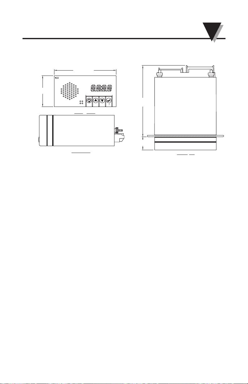
4.33 [110.1]
MAX
0.80 [20.4]
TOP VIEW
SIDE VIEW
FRONT VIEW
1.89 [48.0]
3.78 [96.0]
EGAOM
MODE
DOWN
UP
SET
TALK
UV1000-PM
V
TC
I
C
AL
R
Figure 2.14 Meter–Overall Dimensions
2
UV1000-PM Programmable Universal Verbalizer
2.4 Panel Mounting, Panel Cutout, Overall Dimensions (cont.)
Page 16
3-1
3
Verbalizer - User Configuration Software
• In Command talk mode, if you Press and hold the Talk/Set Button for four
seconds it will switch to Continuous talk mode.
• In Continuous talk mode, if you press and hold the Talk/Set Button for four
seconds, it will switch to Command talk mode.
▼
▼
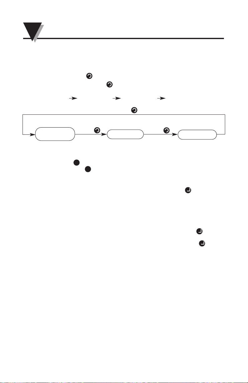
3.1 MODE button - Change the Input Selections
Press the MODE button to select the input for the display and
verbalize.
TC input Voltage input Current input TC input
3.2 UP and Down Buttons
UP Button – With Button Press the Volume Goes Up
DOWN Button – With Button Press the Volume Goes Down
3.3 TALK/SET Button
a. At Command talk mode - you must press TALK/SET button to
listen the measurement.
b. At Continuous talk mode – The Verbalizer will talk the measurement
continuously at the selected talking interval. The factory default
talking interval is 3s. The interval selecting range is 0 to 120 seconds.
c. Switch between Command talk and Continuous talk mode
Section 3 – Front Panel Button Operation
▼
▼
“Thermocouple
Input”
“Voltage Input”
“Current Input”
Press MODE
▼
Press
MODE
▼
▲
▼
Press
MODE
▼
▼
Page 17
Section 4 - Verbaview™ – User Configuration Software
4.1 Verbaview™ Installation
Insert the Verbaview™ software CD into your CD-ROM, the install
program will run install automatically and the software will guide you
through the whole the installation.
If the program didn’t install automatically, click Windows Start Run,
click Browse… find your D: drive and select setup.exe file and then
click OK button
You can also visit www.omega.com or our ftp website to update latest
Verbaview™ software ftp://ftp.omega.com/public/TEMPERATUREGroup/products/UV1000-PM/
4.2 Starting the Verbaview™ Program
Connect the Universal Verbalizer UV1000 to your PC through RS232
cable. Click Start Programs Verbaview UV-1000 Verbaview
UV-1000 to run the program.
Note: The LED display may flashing or flickering during the
communication with PC when you are configuration the unit.
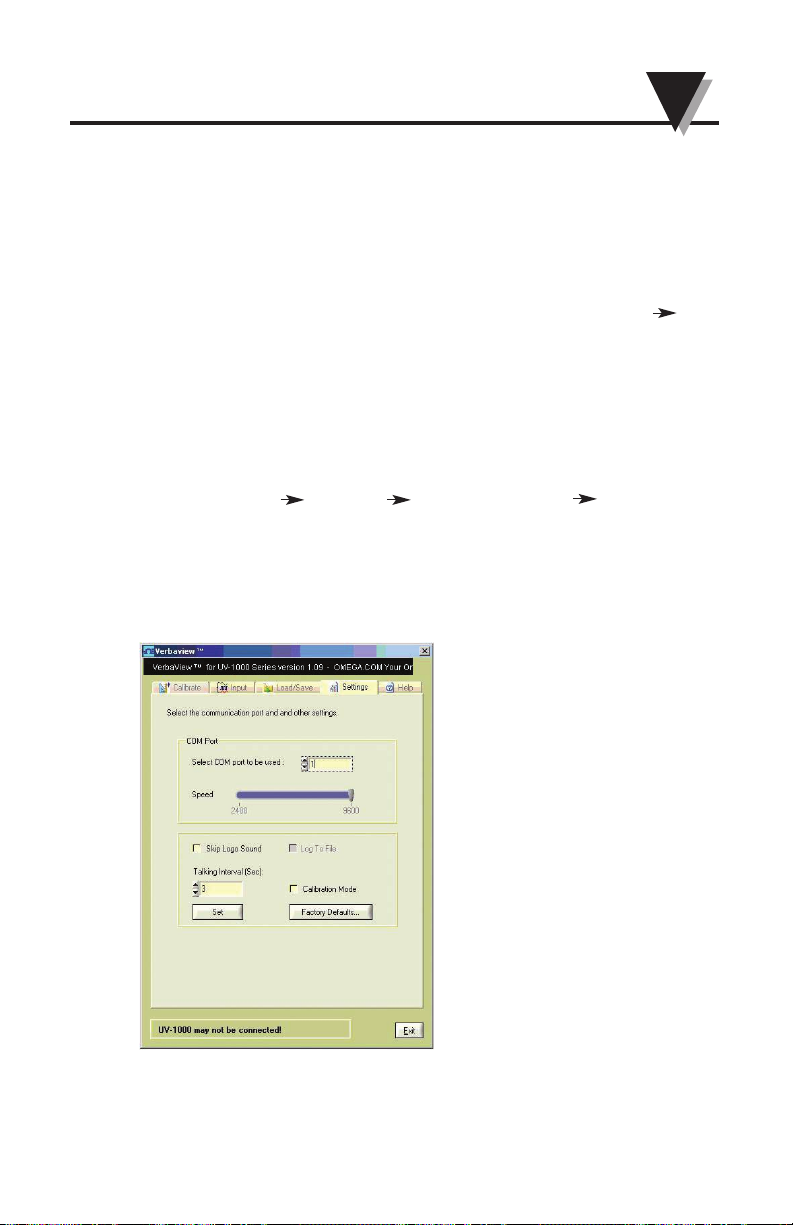
4.3 Settings Tag
Go to the Settings tag
4-1
4
Verbalizer - User Configuration Software
Page 18
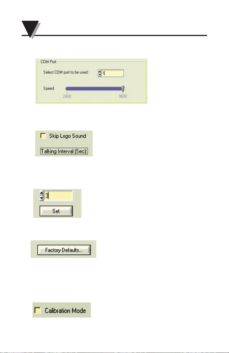
4.3.2 Check the “Skip Logo Sound” to disable the sound effect during
the Verbaview program at start up.
4.3.3 Talking Interval.
You can set the talking time interval from 0 to 120 seconds. The default talking
interval is 3 seconds.
4.3.4 Factory default settings Button
If you click this button the Universal Verbalizer settings will go back to
manufacture default settings. Please see Appendix 1 for the complete default
settings.
4.3.5 Calibration mode
This function is for factory use only. It is password protected.
4-2
4
Verbalizer - User Configuration Software
4.3.1 Select the COM port which connects to your Universal Verbalizer
and the Speed (Baud Rate) is fixed at 9600bit/sec
Page 19
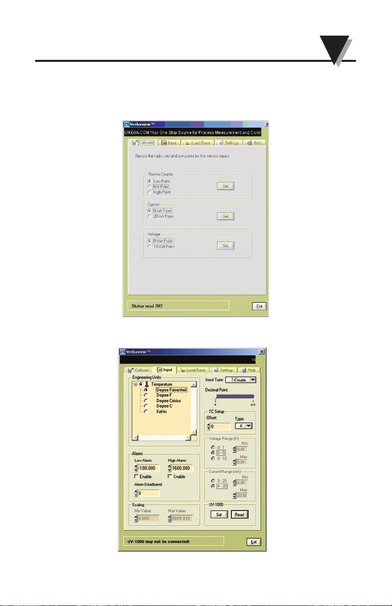
4.4 Calibrate Tag
This function is disabled (grayed out) and is only for factory calibration use.
4.5 Input Tag
4-3
4
Verbalizer - User Configuration Software
Page 20
4-4
4
Verbalizer - User Configuration Software
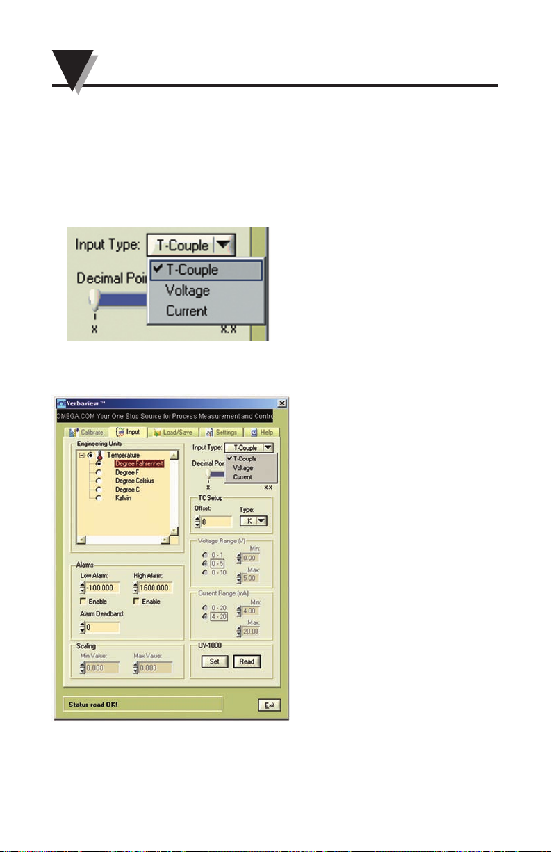
4.5.1 Select the Input Type
You can select T-Couple (Thermocouple) Input, Voltage Input or
Current Input by click the pull down list. On the panel meter display,
there are LED indicators to indicate the input selections. ( see 2.1 for
indication references)
• Thermocouple input configuration interface
Page 21
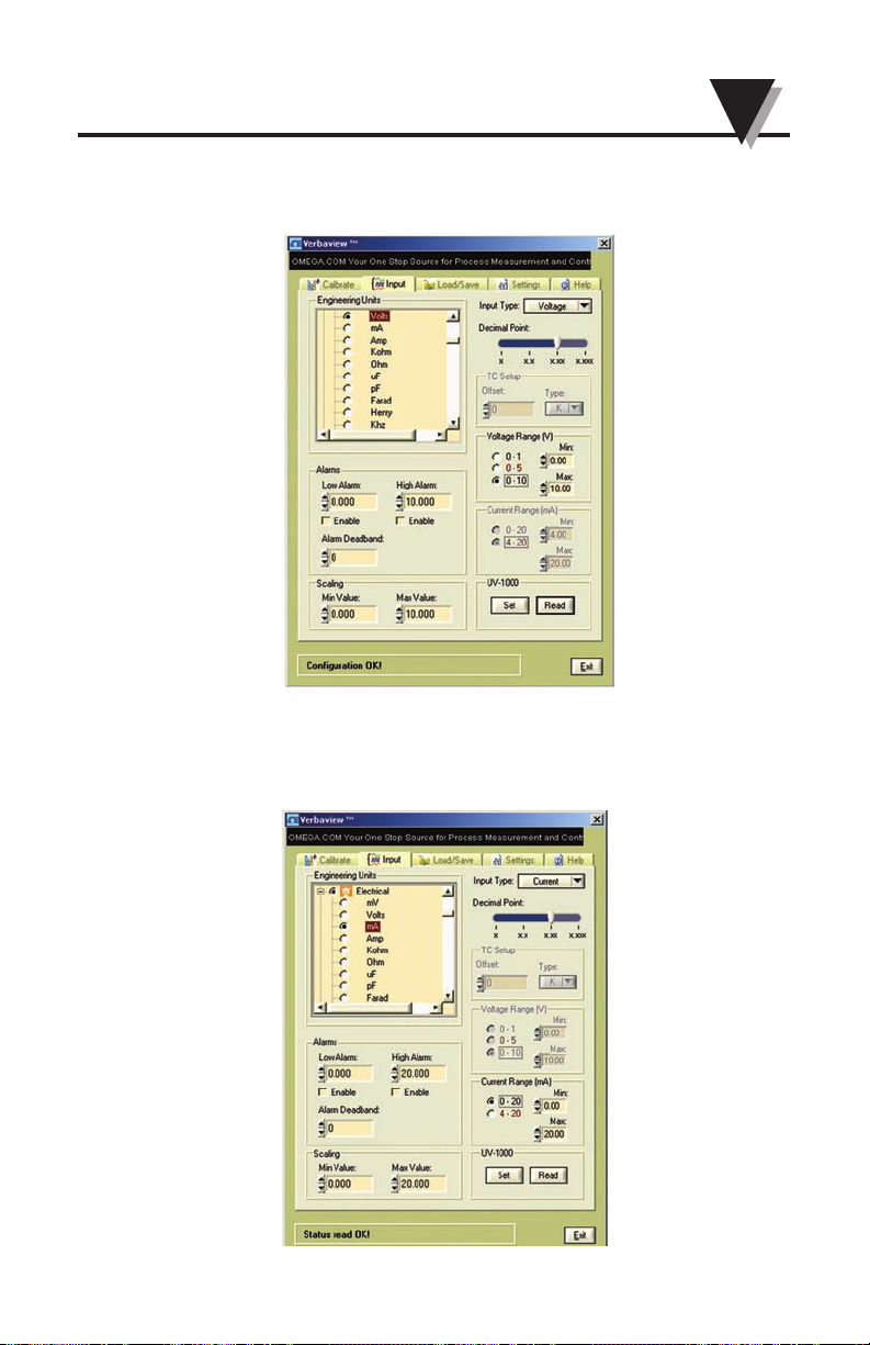
• Voltage input configuration interface
• Current input configuration interface
4-5
4
Verbalizer - User Configuration Software
Page 22
4-6
4
Verbalizer - User Configuration Software
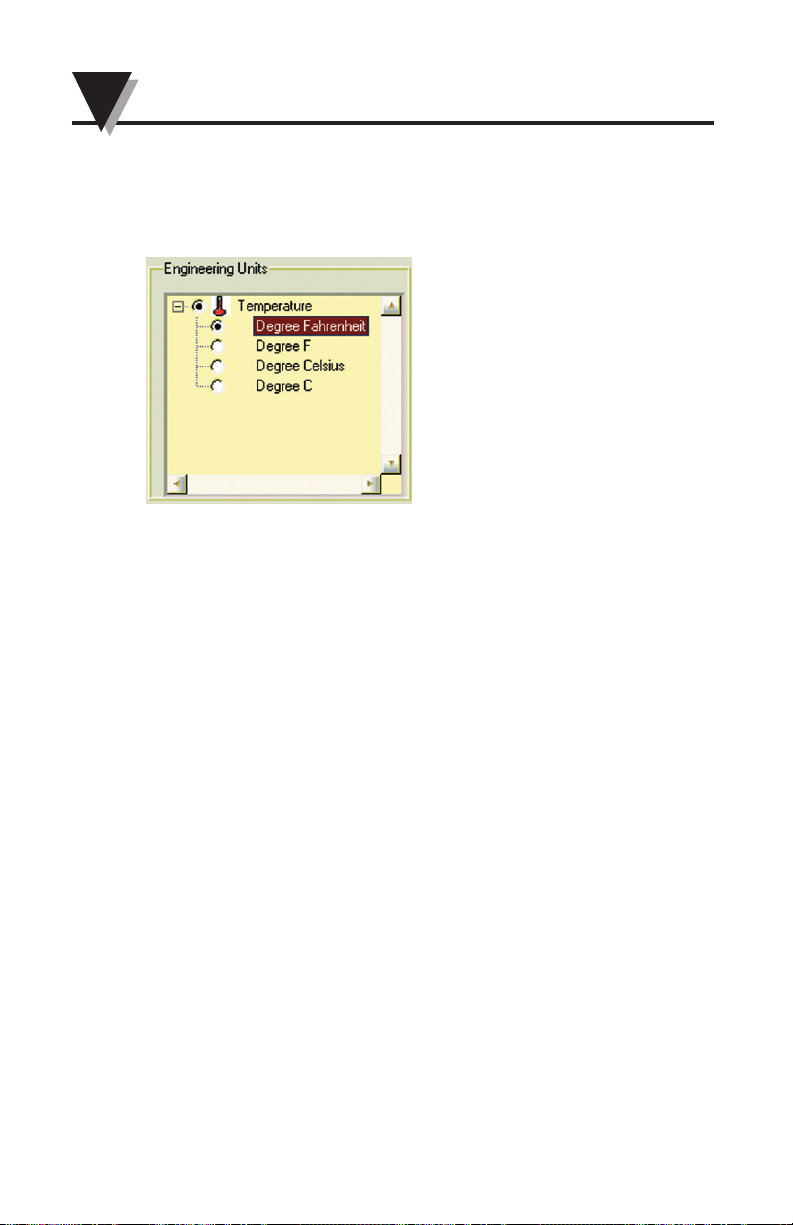
4.5.2. Select the Engineering Unit
Select the Engineering Unit from the trees at Engineering Units window
after you select the Input type.
The Engineering Units categories are:
• Acceleration
• Area
• Conductivity
• Dissolved
• Electrical
• Energy
• Flow
• Force
• Humidity
• Length
• pH
• Power
• Pressure
• Salinity
• Sound
• Temperature
• Time
• Turbidity
• Vacuum
• Velocity
• Viscocity
• Volume
• Weight
Please see Appendix 2 on Page 5-4 Engineering Units Table
for Complete Engineering Units Selection.
Page 23
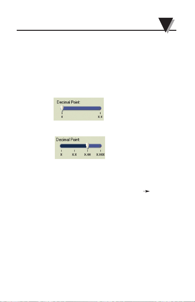
4.5.3 Select the Decimal Point
You can select the Decimal Point for the verbal number. You can select
no decimal point, one decimal, two decimal point and up to three
decimal point.
Thermocouple Input: x, x.x
(Note: When you select one decimal point in TC input mode, the
temperature display resolution on the LED display will be 0.5 ∞F/∞C)
Voltage and Current Input: x, x.x, x.xx, x.xxx;
For example:
For Thermocouple input, the temperature measurement is 75.3°F. If
you select Decimal Point is ‘x.x’, then the Verbalizer will talk “ Seventy
Five Point Three Degrees F” –> 75.3°F; If you select Decimal point is ‘x’,
then the Verbalizer will talk “ Seventy Five Degrees F” 75°F;
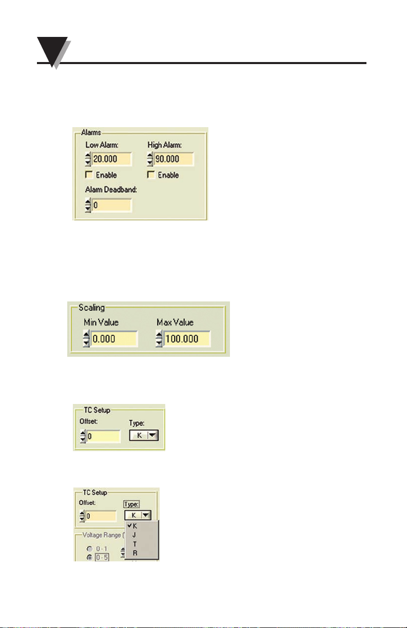
4.5.4 Alarms Settings
- Set the High or Low alarm, Alarm Deadband value
- Enable or disable the High or Low alarm settings
When the alarm condition occurs, the followings will happen:
• The LED display will turn to RED
• The red LED ‘AL’ on the display will flashing
• The corresponding alarm output relay will be energized
• The Verbalizer will keep on saying “High alarm” or “Low alarm”
4-7
4
Verbalizer - User Configuration Software
Page 24
4-8
4
Verbalizer - User Configuration Software
If you set the Alarm Deadband value, the high alarm will not stop until
the display value below (High Alarm value - Alarm Deadband value)
and the low alarm will not stop until the display value above the (Low
Alarm + Alarm Deadband) value.
4.5.5 Scaling – (Voltage and Current input only, will be grayed out in
other analog input selection)
Please reference the following application examples for your proper
setting scaling values
Input the Engineering Unit range value to the text boxes
These text boxes are for Engineering Units input values:
4.5.6 TC Setup (Thermocouple input only, will be grayed out in other
analog input selection)
• Offset – input range ±1000
• Type – You can select Type K, J, T or R thermocouple input from the
pull down list.
Page 25
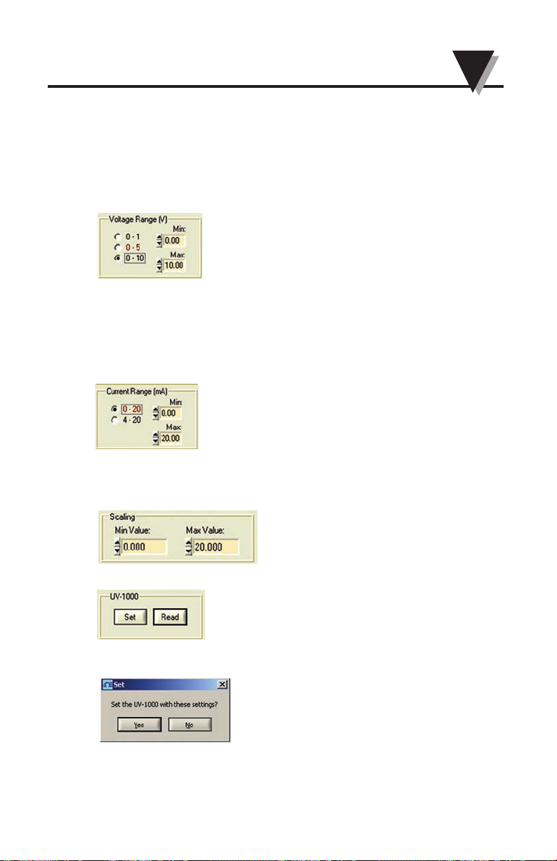
4.5.7 Voltage Range – (Voltage input only, will be grayed out in other
analog input selection)
You can select the voltage range 0-1v, 0-5v or 0-10v. Also you can type
in the specified Min and Max voltage value into the text box. The
maximum voltage value should not exceed 10Vdc and the minimum
voltage values should not less than 0 voltage.
4.5.8 Current Range – (Current input only, will be grayed out in other
analog input selection)
You can select the current range 0-20 mA or 4-20 mA. Also you can
type in the specified Min and Max current value into the text box. The
maximum current value should not exceed 20mA and the minimum
current value should not less than 0 mA.
4.5.9 Scaling the Engineering Unit
The Scaling function will gray out in Thermocouple input, but will be
enabled in Voltage or Current input.
4.5.10 The Set and Read buttons
When you Click Set button, you will be asked for “Set the UV-1000 with
these settings?”
Click “OK” to update the settings or click “No” to the cancel settings’
change.
When you click Read button, you will read the current settings from the
UV1000 device.
4-9
4
Verbalizer - User Configuration Software
Page 26
4-10
4
Verbalizer - User Configuration Software
4.5.11 Application Examples of Rescaling the Engineering Unit
4.5.11.1 Voltage Input Settings and Rescaling
Application Example 1:
General Purpose Output Pressure Transducer
Omega Model Number: PX303-100A5V
Output: 0.5 – 5.5 Vdc
Pressure Range: 0-100 PSIA
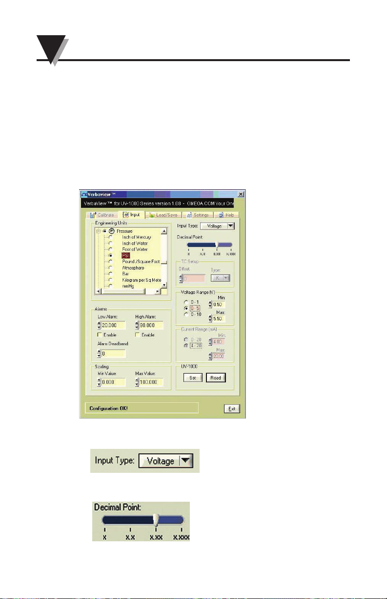
The following PC user interface graphic, showing all the configuration
settings and values for this application example.
a. Select the Voltage Input
c. Select the decimal points – 2 decimal points
Page 27
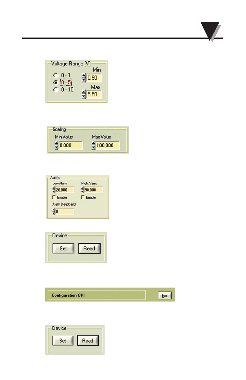
d. Input the voltage range value to the text boxes
These text boxes are for the voltages input values:
e. Input the Engineering Unit range value to the text boxes
These text boxes are for Engineering Units input values:
f. Set the High or Low alarm, Alarm Deadband value
Enable or disable the High or Low alarm settings
g. Click the Set button to send the settings to Universal Verbalizer.
h. After a few seconds, you will see ‘Configuration OK!’ message at the
bottom of the User interface. Now you are done with the rescaling and
also updated other settings for the Verbalizer.
i. If you click the
Read button, you will get all the settings from the
Universal Verbalizer at Voltage input mode.
4-11
4
Verbalizer - User Configuration Software
Page 28
4-12
4
Verbalizer - User Configuration Software
Application Example 2:
High Temperature Handheld Infrared Thermometer
Omega Model Number: OS523E
Analog Output: 1 mV/deg
Temperature Range: 0 to 2500°F
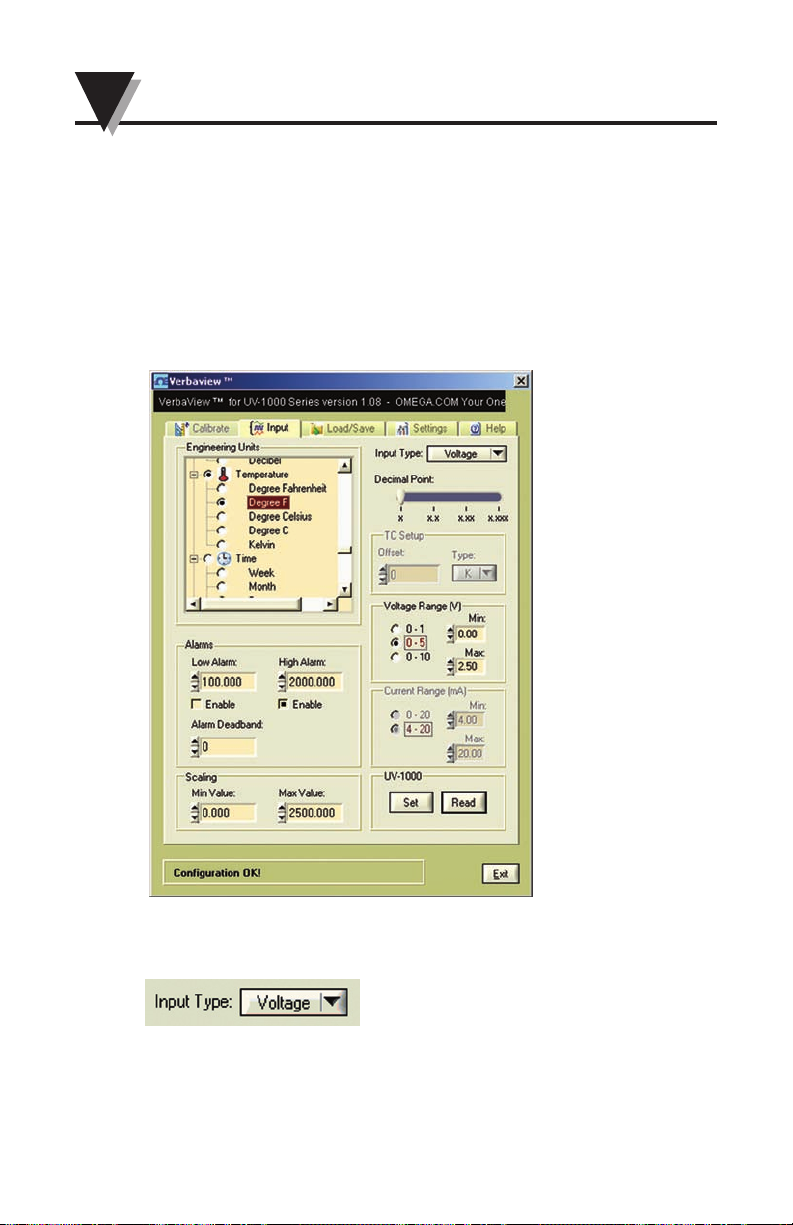
The following PC user interface graphic, showing all the configuration
settings and values for this application example.
a. Select the Voltage input
Page 29
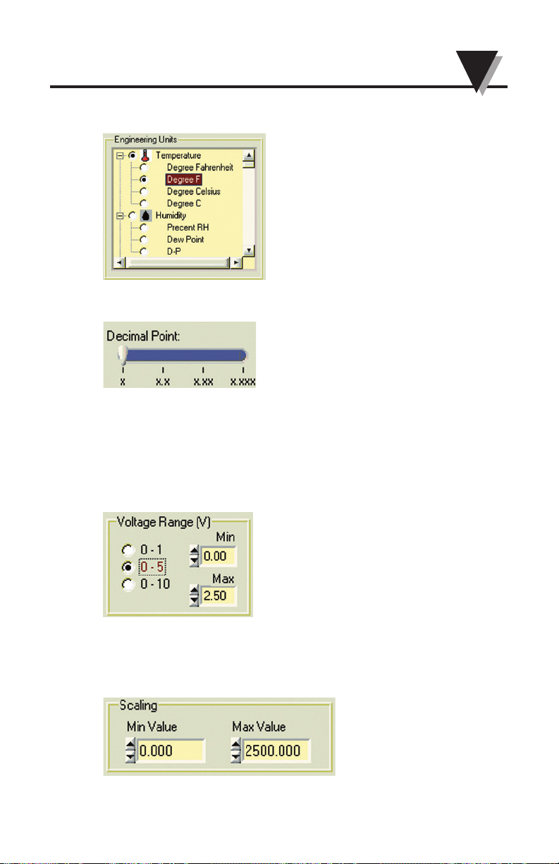
b. Select the Engineering Unit – Degree F.
c. Select the decimal points x – No decimal point
d. Input the voltage range value to the text boxes
Calculate the Voltage Range: Since the Analog Output: 1 mV/deg and
the Temperature Range is 0 - 2500°F
The Voltage Min = 1 mV/deg * 0 deg = 0 mV = 0 V;
The Voltage Max = 1 mV/deg * 2500 deg = 2500mV = 2.5 V;
Type these calculated voltage values into the Min and Max text boxes:
e. Input the Engineering Unit range value to the text boxes according to:
Temperature Range: 0 - 2500°F
So, the Min Value is 0 and the Max Value is 2500.
4-13
4
Verbalizer - User Configuration Software
Page 30
4-14
4
Verbalizer - User Configuration Software
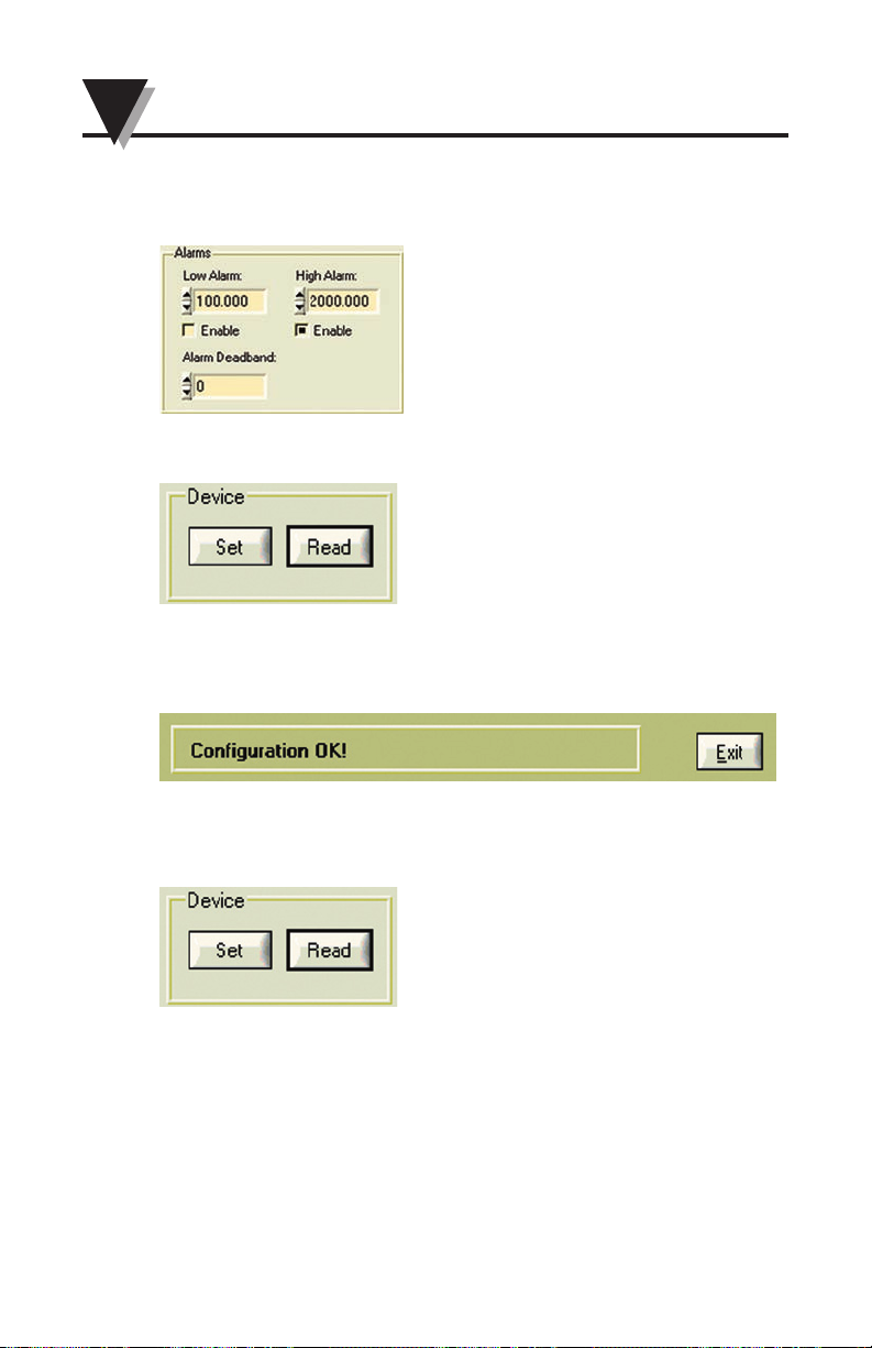
f. Set the High or Low alarm Value, and Alarm Deadband
enable or disable the High or Low alarm settings.
g. Click the Set button to send the settings to Universal Verbalizer.
h. After a few seconds, you will see ‘Configuration OK!’ message at the
bottom of the User interface. Now you are done with the rescaling and
also updated other settings for the Verbalizer.
i. If you click the Read button, you will get the all the settings from the
Universal Verbalizer at Voltage input mode.
Page 31
4.5.11.2 0 to 20 mA or 4 to 20 mA Current Input Settings and
Rescaling
Application Example 3:
Miniature Low Cost Non-Contact IR
Temperature Sensor/Transmitter
Omega part number: OS101-MA Transmitter with 4 to 20 mA output
Current Output: 4 to 20 mA
Temperature Range: 0 to 1000°F
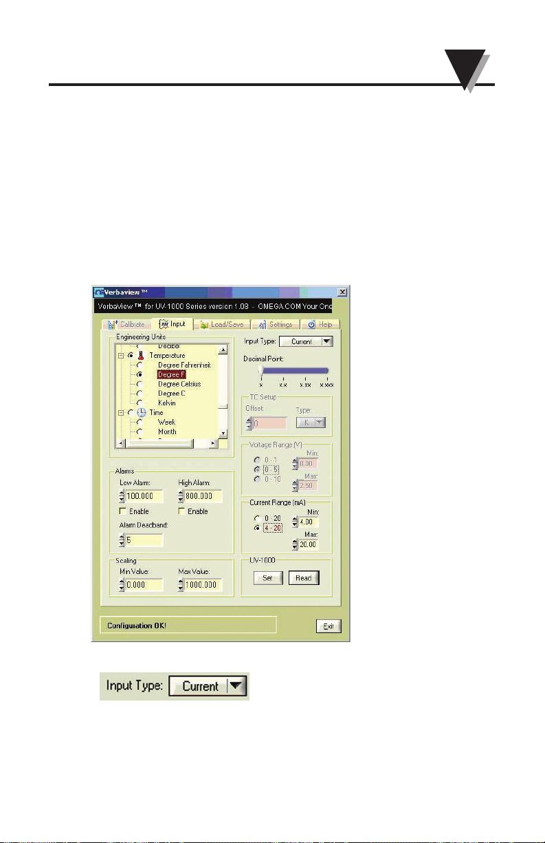
The following PC user interface graphic, showing all the configuration
settings and values for this application example.
a. Select the Current input
4-15
Verbalizer - User Configuration Software
Page 32
4-16
4
Verbalizer - User Configuration Software
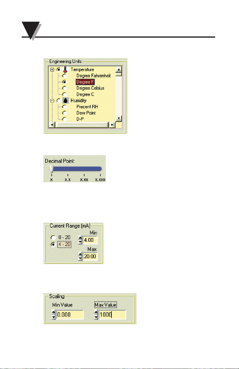
b. Select the Engineering Unit – Degree F.
c. Select the no decimal points – x
d. Input the Current range value to the text boxes
This Transmitter Current Output range is : 4 – 20 mA
Select Current Range 4-20 or just type in 4 to Min text box and 20 to
Max text box
e. Input the Engineering Unit range value to the text boxes
The Transmitter temperature range is: 0-1000°F
So, type in 0 in Scaling Min Value, 1000 in Scaling Max Value
Page 33
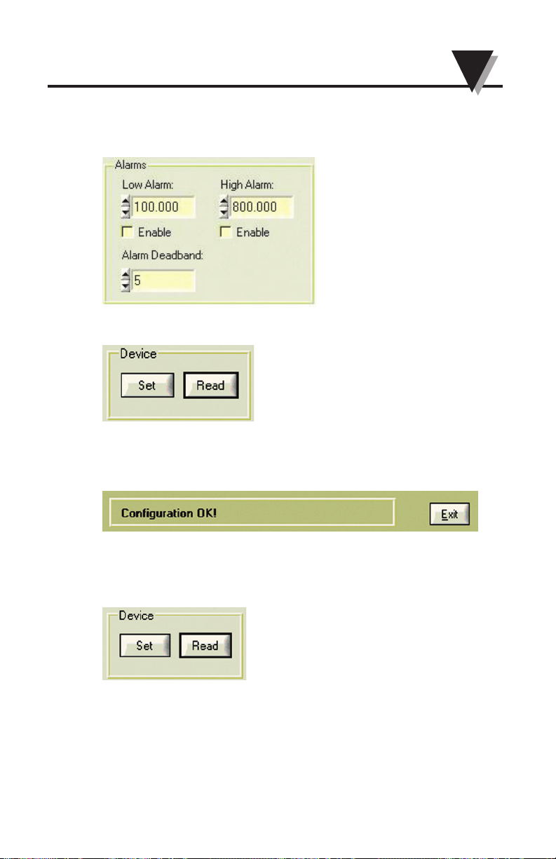
f. Set the High or Low alarm value and Alarm Deadband
Enable or disable the High or Low alarm settings
g. Click the Set button to send the settings to Universal Verbalizer
h. After a few seconds, you will see ‘Configuration OK!’ message at the
bottom of the User interface. Now you are done with the rescaling and
also updated other settings for the Verbalizer.
j. If you click the Read button, you will get all the settings from the
Universal Verbalizer at Current input mode
4-17
4
Verbalizer - User Configuration Software
Page 34
4-18
4
Verbalizer - User Configuration Software
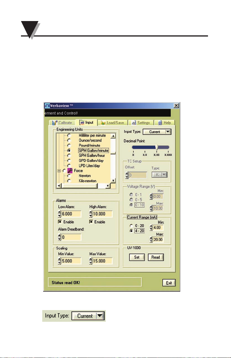
Application Example 4:
Liquid Flow Transmitters
Omega Model number: FPR205-PC 500, transmitter with clear cover
Current Output: 4 – 20 mA
Flow Measuring Range: 0.5 to 15.0 GPM
The following PC user interface graphic, showing all the configuration
settings and values for this application example.
a. Select the Current input
Page 35
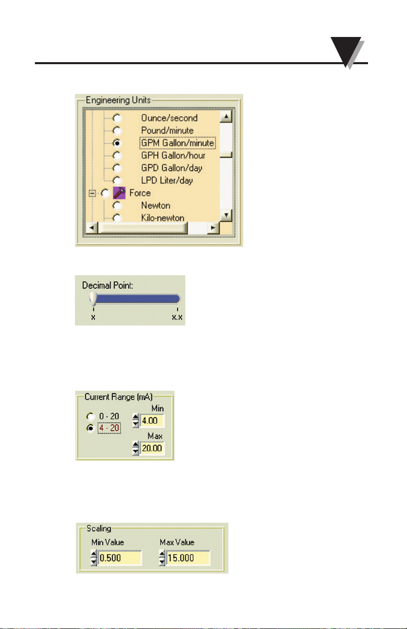
b. Select the Engineering Unit – GPM at Engineering Unit window
c. Select the one decimal points – x.x
d. Input the Current range value to the text boxes
This transmitter Current Output is 4 – 20 mA
Select Current Range to 4-20 or type in the Min and Max value in the text
boxes.
e. Input the Engineering Unit range value to the text boxes
This transmitted Flow Measuring Range: 0.5 to 15.0 GPM
Type in the Scaling Min and Max Value according to the Measuring
Range
4-19
4
Verbalizer - User Configuration Software
Page 36
4-20
4
Verbalizer - User Configuration Software
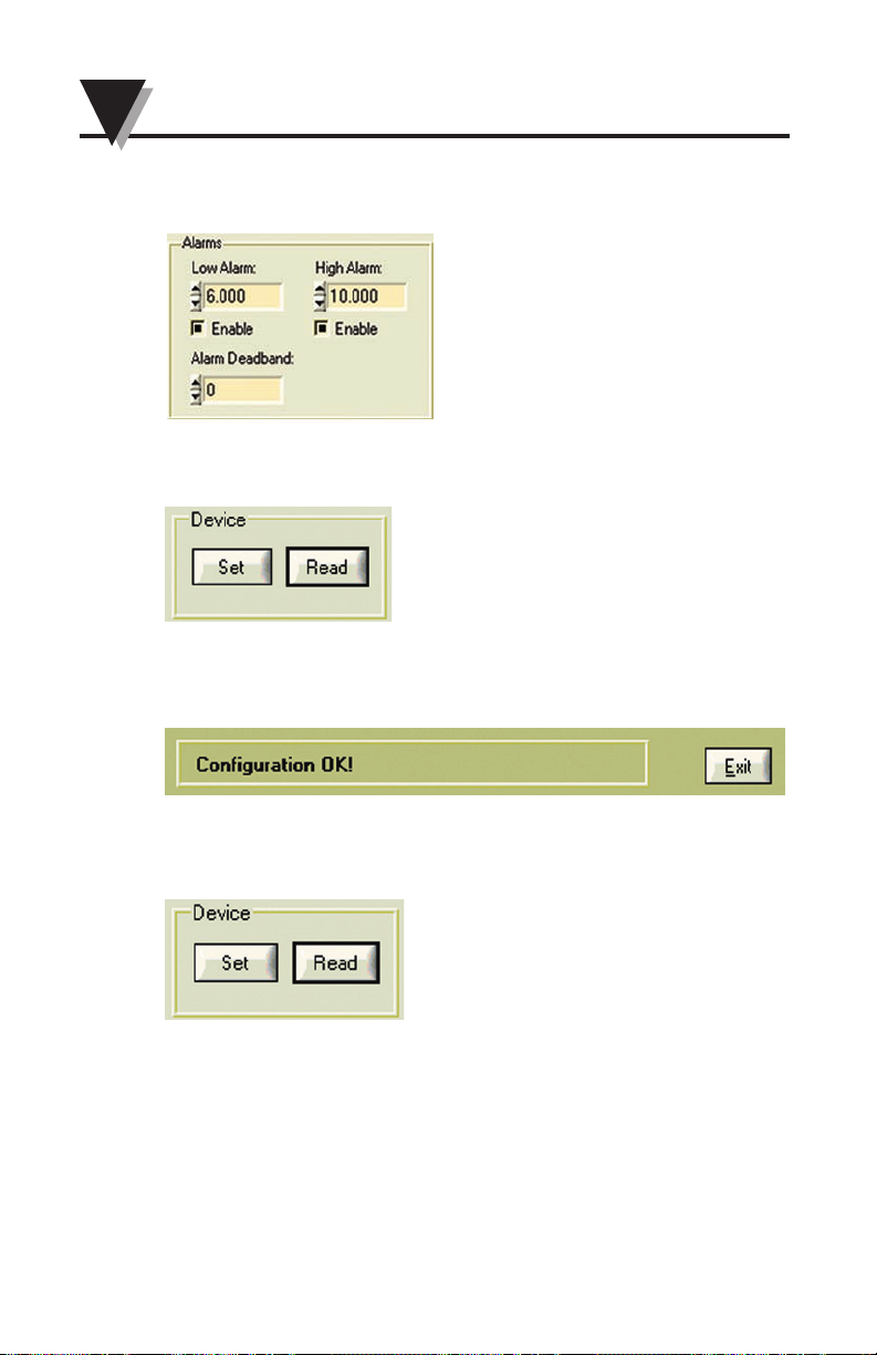
f. Set the High or Low alarm value and the Alarm Deadband
Enable or disable the High or Low alarm settings
g. Click the Set button to send the settings to Universal Verbalizer.
h. After a few seconds, you will see ‘Configuration OK!’ message at the
bottom of the User interface. Now you are done with the rescaling
and also updating other settings for the Verbalizer.
i. If you click the Read button, you will get all the settings from the
Universal Verbalizer at Current input mode.
Page 37
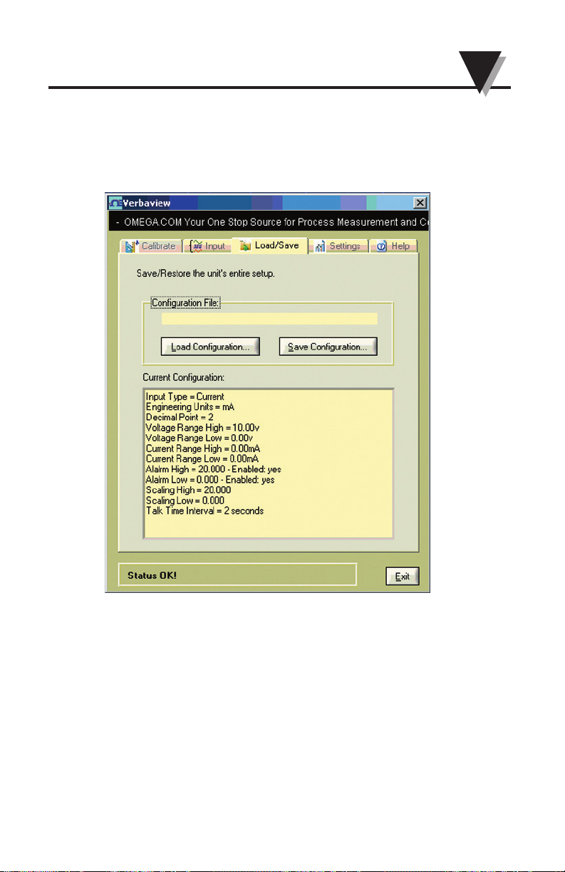
4.6 Load/Save Tag
At this tag, you can Load the saved previous configuration settings from your
PC to the program. Or you can save the Configuration settings to your PC for
future reference.
4-21
4
Verbalizer - User Configuration Software
Page 38
4
Verbalizer - User Configuration Software
4.7 Error Messages
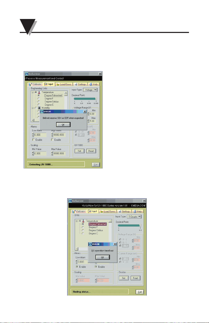
• You may get the error message “Did not receive SOH or EOT when expected”.
If this happens, please make sure the Universal Verbalizer power is turn on,
check the COM port selection in Settings tag, the cable connections between PC
and Universal Verbalizer and then try again
• You may get “I/O operation time out” error messages during the configuration. If this happens, please check the COM port, cable connection between PC
and Universal Verbalizer and make sure the universal Verbalizer power is turn
on. Then try again
4-22
Page 39

5
Verbalizer - User Configuration Software
5-1
Section 5 - Specifications:
Voltage Input: 0-10 Vdc
Input Impedance: 500 K ohms
Current Input: 0-20 mA, 4-20 mA
Voltage and Current Input:
Accuracy: 0.2% of full scale
Thermocouple Input: Type K, J, T and R
Thermocouple Range: Type K: -100 to 871°C (-148 to 1600°F)
Type J: -75 to 650°C (-103 to 1202°F)
Type T: -75 to 380°C (-103 to 716°F)
Type R: 260 to 1710°C (500 to 3110°F)
Thermocouple Input Accuracy: Type K, J and R: 2.0°C (3.6°F)
Type T: 1.0°C (1.8°F)
Thermocouple Input Offset: ±1000
Command/Continuous Talk: Set via front button
High & Low Alarm Set Points:
And the Alarm Deadband: Set via RS232 PC interface
High & Low Alarm:
Set Value Range: ±9999.999
High & Low Alarm Deadband:
Set Value Range: 0~ 1000
High & Low Alarm Relay Output: 2 Form C (SPDT) relays, 3 A @ 30 Vdc, or
3 A @ 250 Vac, (resistive load)
Engineering Scale: Set via RS232 PC interface
Engineering Scaling
Min & Max Value Range: ±9999.999
Engineering Unit: Over 100 audio Engineering Unit selectable
Set via RS232 PC interface
Volume Control: Set via front button, 8 levels at 4 dB intervals
Power: 90 to 240 Vac, 50 to 400 Hz
110 to 375 Vdc, equivalent voltage
4 W without external speaker
Color Change LED Display: GREEN - normal operation condition
AMBER - in TC open or overrange condition
RED - in alarm condition
Low Battery Indication: Red LED, Flashing
Speech Sampling Rate: 8 KHz
Build in Speaker: Built-in, 8 Ohms
External Speaker: 3w, 8 Ohms
Operating Ambient Temperature: 0 to 50°C (32 to 122°F)
Operating Relative Humidity: 0 to 95% RH (Non-condensing)
Dimensions: 131 L x 96 W x 48 mm D
(5.13 x 3.78 x 1.89")
Weight: 250 g (0.55 lb)
Page 40
5
Verbalizer - User Configuration Software
5-2
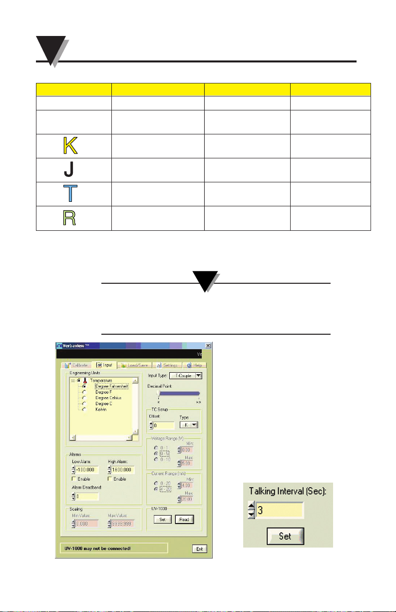
Input Types Range Accuracy
Process Voltage 0 to 10 Vdc
0.2% of full scale
Process Current
0 to 20 mA or
0.2% of full scale
4 to 20 mA
CHROMEGA®- -148 to 1600°F 3.6°F
ALOMEGA
®
-100 to 871°C 2°C
Iron-Constantan
-103 to 1202°F 3.6°F
-75 to 650°C 2°C
Copper-Constantan
-103 to 716°F 1.8°F
-75 to 380°C 1.0°C
Pt/13%Rh-Pt
500 to 3110°F 3.6°F
260 to 1710°C 2°C
Inputs
Appendix 1
Factory Default Settings
The Factory default input is TC input, Command Talk and the
Talking Interval is 3s and each input default settings are as
followings
NOTE:
Talking interval at Settings tag
Page 41

• TC Input:
Engineering Unit: Degree F
TC Type: K
TC Offset: 0
Decimal Point: x – No decimal points
Alarms are disabled
Low Alarm: -100
High Alarm: 1600
Alarm Deadband: 0
Talking interval: 3 s
• Voltage Input:
Engineering Unit: volt
Decimal Point: x.xx – Two decimal
points
Alarms are disabled
Low Alarm: 0
High Alarm: 10
Alarm Deadband: 0
Voltage Range(V): 0 to 10v
Voltage Min: 0.00
Voltage Max: 10.00
Rescaling Min Value: 0
Rescaling Max Value: 10
Talking Time Interval: 3s
• Current Input:
Engineering Unit: mA
Decimal Point: x.xx – Two decimal
points
Alarms are disabled
Low alarm: 0
High alarm: 10
Alarm Deadband: 0
Current Range(V): 0 to 20 mA
Current Min: 0.00
Current Max: 20.00
Rescaling Min Value: 0
Rescaling Max Value: 20
Talking Time Interval: 3 s
5-3
5
Verbalizer - User Configuration Software
Page 42

5-4
5
Verbalizer - User Configuration Software
Appendix 2
Engineering Units Table:
Categories Engineering Units --> For the tree of PC GUI Note
Acceleration Centimeter per square second Metric
g
Meter per square second
Foot per square second English
Inch per square second
Area Are Metric
Square centi-meter
Square deci-meter
Square meter
Square kilo-meter
Square nanometer
Square micrometer
Acre English
Square foot
Square inch
Square yard
Conductivity mho
Siemens
ppm - Part per million ppm
Dissolved
Oxygen Milligram/liter
Electrical mV
Volts
mA
Amp
Kohm
Ohm
uF
pF
Farad
Henry
Khz
Hertz
Page 43

Categories Engineering Units --> For the tree of PC GUI Note
Energy Newton meter English
Inch pound force
Joule
Kilojoule
Gram Calorie
Calorie Metric
Horsepower-hour
Watt Hour
Kilowatt-hour
Electron volt
Flow Gram/second Metric
Kilogram/Minute
Ton/day
LPM
Cubicmeter per minute
Milliliter per minute
Ounce/second English
Pound/Minute
GPM - Gallon/Minute
GPH - Gallon/Hour
GPD - Gallon/Day
LPD - Liter/Day
Force (Strain) Newton Metric
Kilo-Newton
Dyne English
Long
Short
Humidity Percent RH
Dew Point
D-P Dew
Point
Length Nanometer Metric
Millimeter
Centimeter
Decimeter
Kilometer
5-5
5
Verbalizer - User Configuration Software
Page 44

5-6
5
Verbalizer - User Configuration Software
Categories Engineering Units --> For the tree of PC GUI Note
Length cont. Foot English
Inch
Yard
Mile
pH pH
Power Watt
Kilowatt
Horsepower
Calorie (IT) per hour
Pressure Inch of Mercury English
Inch of water
Foot of water
PSI
Pound per Square foot
Atmosphere Metric
Bar
Kilogram per square meter
mmHg
millimeter of water
Pascal
Hecto-Pascal
Kilo-Pascal
Salinity Total dissolved solid
% concentration
Sound Decibel
Temperature Degree Fahrenheit Metric
Degree F
Degree Celsius English
Degree C
Kelvin
Page 45

5-7
Categories Engineering Units --> For the tree of PC GUI Note
Time Week
Month
Day
Hour
Minute
Second
AM
PM
Turbidity NTU - Nephelometric Turbidity Unit
Vacuum Torr
Velocity Meter per second Metric
KPH
Knot's
Foot per second English
Inch per second
Foot per Minute
Inch/Minute
MPH - Mile per hour
Meter
Viscosity Centipoise
Stoke
Centistoke
Volume Cubic meter Metric
Cubic Centimeter
Milliliter
Liter
Barrel English
Gallon
Pint
Quart
Ounce
Weight Gram Metric
Kilogram
Ton
Ounce English
Pound
General Units Units
No Unit Select this, there will be no
engineering units pronounce.
5
Verbalizer - User Configuration Software
Page 46

WARRANTY/DISCLAIMER
OMEGA ENGINEERING, INC. warrants this unit to be free of defects in materials and
workmanship for a period of 13 months from date of purchase. OMEGA’s WARRANTY adds
an additional one (1) month grace period to the normal one (1) year product warranty to
cover handling and shipping time. This ensures that OMEGA’s customers receive maximum
coverage on each product.
If the unit malfunctions, it must be returned to the factory for evaluation. OMEGA’s Customer
Service Department will issue an Authorized Return (AR) number immediately upon phone or
written request. Upon examination by OMEGA, if the unit is found to be defective, it will be
repaired or replaced at no charge. OMEGA’s WARRANTY does not apply to defects resulting
from any action of the purchaser, including but not limited to mishandling, improper
interfacing, operation outside of design limits, improper repair, or unauthorized modification.
This WARRANTY is VOID if the unit shows evidence of having been tampered with or shows
evidence of having been damaged as a result of excessive corrosion; or current, heat, moisture
or vibration; improper specification; misapplication; misuse or other operating conditions
outside of OMEGA’s control. Components in which wear is not warranted, include but are not
limited to contact points, fuses, and triacs.
OMEGA is pleased to offer suggestions on the use of its various products. However,
OMEGA neither assumes responsibility for any omissions or errors nor assumes
liability for any damages that result from the use of its products in accordance with
information provided by OMEGA, either verbal or written. OMEGA warrants only
that the parts manufactured by the company will be as specified and free of
defects. OMEGA MAKES NO OTHER WARRANTIES OR REPRESENTATIONS OF ANY
KIND WHATSOEVER, EXPRESSED OR IMPLIED, EXCEPT THAT OF TITLE, AND ALL
IMPLIED WARRANTIES INCLUDING ANY WARRANTY OF MERCHANTABILITY AND
FITNESS FOR A PARTICULAR PURPOSE ARE HEREBY DISCLAIMED. LIMITATION OF
LIABILITY: The remedies of purchaser set forth herein are exclusive, and the total
liability of OMEGA with respect to this order, whether based on contract, warranty,
negligence, indemnification, strict liability or otherwise, shall not exceed the
purchase price of the component upon which liability is based. In no event shall
OMEGA be liable for consequential, incidental or special damages.
CONDITIONS: Equipment sold by OMEGA is not intended to be used, nor shall it be used: (1)
as a “Basic Component” under 10 CFR 21 (NRC), used in or with any nuclear installation or
activity; or (2) in medical applications or used on humans. Should any Product(s) be used in or
with any nuclear installation or activity, medical application, used on humans, or misused in
any way, OMEGA assumes no responsibility as set forth in our basic WARRANTY/ DISCLAIMER
language, and, additionally, purchaser will indemnify OMEGA and hold OMEGA harmless from
any liability or damage whatsoever arising out of the use of the Product(s) in such a manner.
RETURN REQUESTS/INQUIRIES
Direct all warranty and repair requests/inquiries to the OMEGA Customer Service Department.
BEFORE RETURNING ANY PRODUCT(S) TO OMEGA, PURCHASER MUST OBTAIN AN
AUTHORIZED RETURN (AR) NUMBER FROM OMEGA’S CUSTOMER SERVICE DEPARTMENT
(IN ORDER TO AVOID PROCESSING DELAYS). The assigned AR number should then be
marked on the outside of the return package and on any correspondence.
The purchaser is responsible for shipping charges, freight, insurance and proper packaging to
prevent breakage in transit.
FOR WARRANTY
RETURNS, please have
the following information available BEFORE
contacting OMEGA:
1. Purchase Order number under which
the product was PURCHASED
2. Model and serial number of the product
under warranty, and
3. Repair instructions and/or specific
problems relative to the product.
FOR NON-WARRANTY REPAIRS,
consult
OMEGA for current repair charges. Have the following information available BEFORE
contacting OMEGA:
1. Purchase Order number to cover the
COST of the repair
2. Model and serial number of the product, and
3. Repair instructions and/or specific problems
relative to the product.
OMEGA’s policy is to make running changes, not model changes, whenever an improvement is possible.
This affords our customers the latest in technology and engineering.
OMEGA is a registered trademark of OMEGA ENGINEERING, INC.
© Copyright 2009 OMEGA ENGINEERING, INC. All rights reserved. This document may not be copied, photocopied,
reproduced, translated, or reduced to any electronic medium or machine-readable form, in whole or in part, without
the prior written consent of OMEGA ENGINEERING, INC.
PATENT NOTICE:
U.S. Patent No. 7,400,133. U.S. Patent No. 6,243,021; 6,329,926 used under license. Other U.S. and
International patents pending.
Page 47

Where Do I Find Everything I Need for
Process Measurement and Control?
OMEGA…Of Course!
Shop online at omega.com
SM
TEMPERATURE
䡺⻬
Thermocouple, RTD & Thermistor Probes, Connectors, Panels & Assemblies
䡺⻬
Wire: Thermocouple, RTD & Thermistor
䡺⻬
Calibrators & Ice Point References
䡺⻬
Recorders, Controllers & Process Monitors
䡺⻬
Infrared Pyrometers
PRESSURE, STRAIN AND FORCE
䡺⻬
Transducers & Strain Gages
䡺⻬
Load Cells & Pressure Gages
䡺⻬
Displacement Transducers
䡺⻬
Instrumentation & Accessories
FLOW/LEVEL
䡺⻬
Rotameters, Gas Mass Flowmeters & Flow Computers
䡺⻬
Air Velocity Indicators
䡺⻬
Turbine/Paddlewheel Systems
䡺⻬
Totalizers & Batch Controllers
pH/CONDUCTIVITY
䡺⻬
pH Electrodes, Testers & Accessories
䡺⻬
Benchtop/Laboratory Meters
䡺⻬
Controllers, Calibrators, Simulators & Pumps
䡺⻬
Industrial pH & Conductivity Equipment
DATA ACQUISITION
䡺⻬
Data Acquisition & Engineering Software
䡺⻬
Communications-Based Acquisition Systems
䡺⻬
Plug-in Cards for Apple, IBM & Compatibles
䡺⻬
Data Logging Systems
䡺⻬
Recorders, Printers & Plotters
HEATERS
䡺⻬
Heating Cable
䡺⻬
Cartridge & Strip Heaters
䡺⻬
Immersion & Band Heaters
䡺⻬
Flexible Heaters
䡺⻬
Laboratory Heaters
ENVIRONMENTAL
MONITORING AND CONTROL
䡺⻬
Metering & Control Instrumentation
䡺⻬
Refractometers
䡺⻬
Pumps & Tubing
䡺⻬
Air, Soil & Water Monitors
䡺⻬
Industrial Water & Wastewater Treatment
䡺⻬
pH, Conductivity & Dissolved Oxygen Instruments
M4788-0709
 Loading...