

Page 1
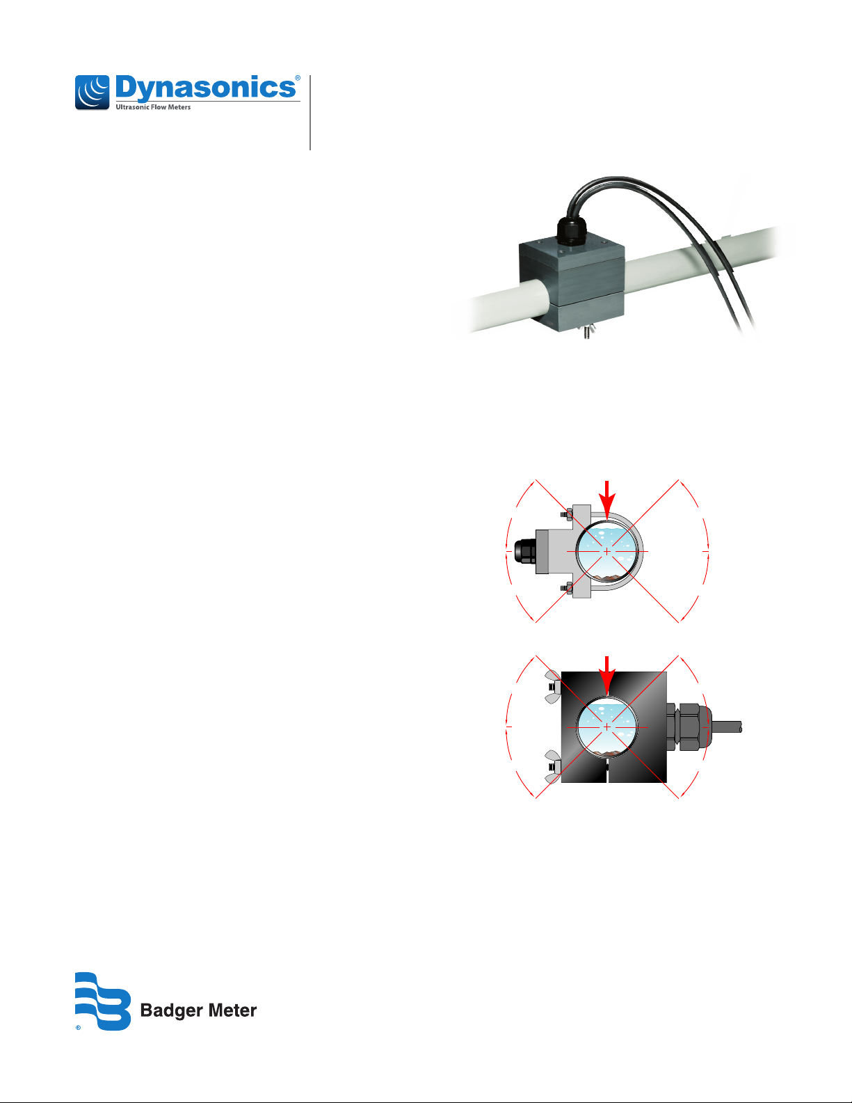
Split Housing
Transducers
Small Pipe, Fixed Size Transit Time Ultrasonic Transducers
INTRODUCTION
This document explains how to install small pipe transit time
ultrasonic integral transducers and transducers with remote
mounting. The transducers can be installed vertically
or horizontally.
The transducers have integrated transmitter and receiver
elements that eliminate the requirement for spacing
measurement and alignment.
PREINSTALLATION
REQUIREMENTS
Program the Meter
Before the flow meter will be operational, you must select the
optimum transmission mode, enter the site information, and
enter the uid and pipe properties into the ultrasonic flow
meter. For detailed instructions, see the user manual for your
flow meter.
Select a Pipe Location for the Transducers
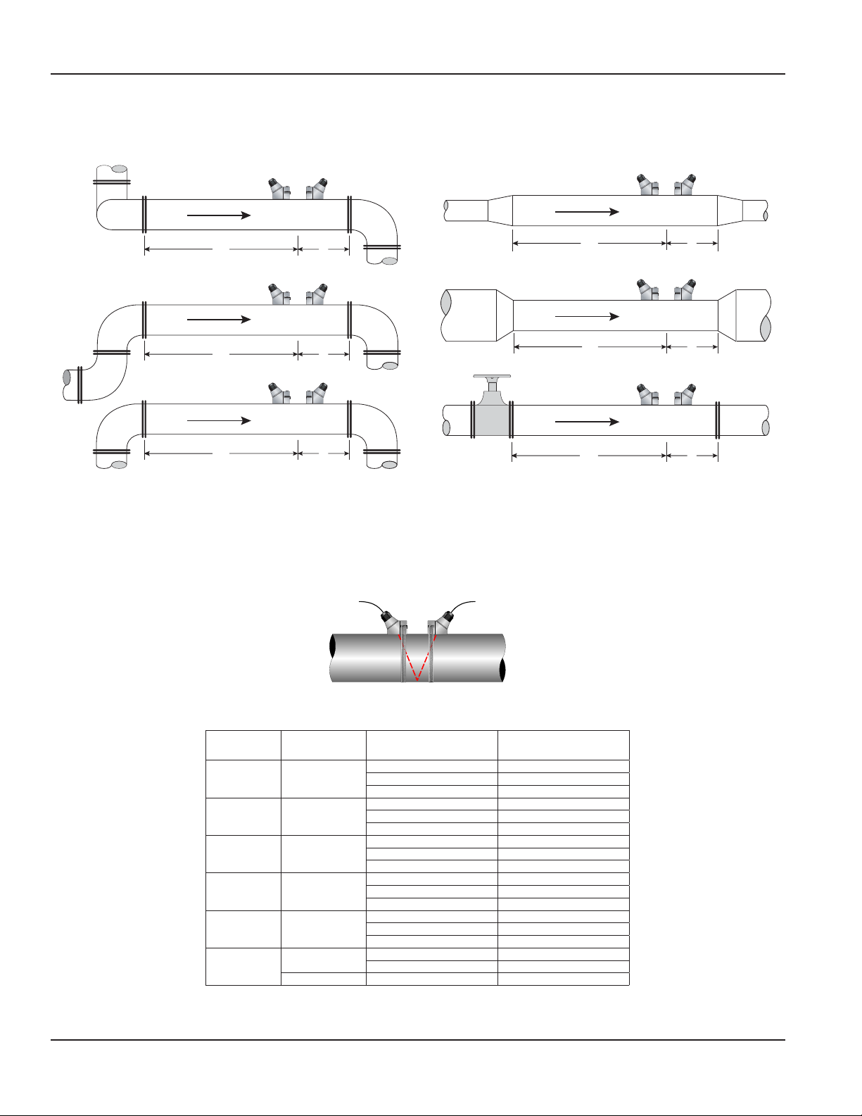
Select a location for the transducers on a section of pipe that
has at least 10 pipe diameters upstream of the transducers
and 5 pipe diameters downstream. See “Figure 2: Piping
configuration and transducer positioning” on page2.
For example, if a 2 in. pipe is being measured, the minimum
upstream pipe in front of the transducer should be 20 in.
and the minimum downstream pipe behind the transducer
should be at least 10 in.
Pipe runs shorter than the minimums may sometimes be
used with reduced accuracy. There is no way to determine
how much accuracy is sacrificed without doing
in-field testing.
For installations where the 10/5 pipe diameters rule cannot
be followed, divide the total length of available straight pipe
into thirds and mount the rail with 2/3 of the pipe upstream
and 1/3 of the pipe downstream.
A full pipe is absolutely essential for making accurate flow
measurements. The flow meter cannot determine if the pipe
is full or not. If the pipe is partially full, the meter will
over-report the amount of flow by the percentage of the pipe
that is not filled with liquid or may not detect any flow.
Install the mounting system in an area where the transducers
will not be inadvertently bumped or disturbed.
Avoid installations on downward flowing pipes unless
adequate downstream head pressure is present to overcome
partial filling of—or cavitation in—the pipe.
Top of
Pipe
45°
YES
YES
45°
U-Bolt
Top of
Pipe
45°
YES
45°
Figure 1: Transducer positioning
45°
45°
45°
YES
45°
IND-UM-02649-EN-05 (March 2021)
Installation Guide
Page 2
Pre-Installation Requirements
Piping Congurations and Transducer Positioning
Figure 2 shows the number of pipe diameters required downstream and upstream of the transducers for various
piping configurations.
Flow
24 5
Flow
14 5
Flow
10 5
Figure 2: Piping configuration and transducer positioning
Flow
10 5
Flow
10 5
Flow
24 5
The system will provide repeatable measurements on piping systems that do not meet these pipe diameter requirements, but
the accuracy of the readings may be influenced.
Mounting Conguration
The mounting configuration for these transducers is V-Mount, where the sound traverses the pipe twice. V-Mount is a
compromise between travel time and signal strength.
TOP VIEW
OF PIPE
Figure 3: V-mount configuration
The frequency setting depends on the pipe material.
Pipe Size
1/2 in. 2 MHz
3/4 in. 2 MHz
1 in. 2 MHz
1-1/4 in. 2 MHz
1-1/2 in. 2 MHz
2 in.
Frequency
Setting
1 MHz
2 MHz D**CS Stainless Steel
Table 1: Transducer frequency settings
Page 2 March 2021IND-UM-02649-EN-05
TFX-500w/TFX-5000
Transducer
D**CA ANSI
D**CG Copper
D**CM Stainless Steel
D**CB ANSI
D**CH Copper
D**CN Stainless Steel
D**CC ANSI
D**CT Copper
D**CP Stainless Steel
D**CD ANSI
D**CJ Copper
D**CQ Stainless Steel
D**CE ANSI
D**CK Copper
D**CR Stainless Steel
D**CF ANSI
D**CL Copper
Pipe
Page 3
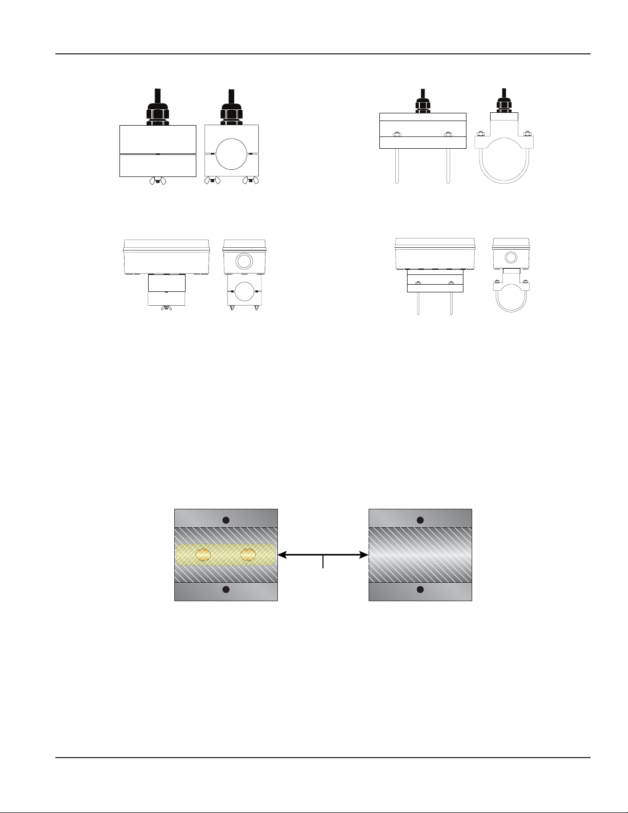
Remote System with Small Pipes
Installation Procedure
Top View
Figure 4: Pipes and tubing 1/2…2 in.
Side View
Figure 5: U-bolt connections, ANSI and copper 2 in.
Side ViewTop View
Integral Systems with Small Pipes
Side ViewTop View
Figure 6: Integral
Top View Side View
Figure 7: Integral with u-bolt
INSTALLATION PROCEDURE
The small pipe transducers are fixed to pipe sizes between 1/2…2 in. Do not attempt to mount the transducers onto a pipe
that is either too large or too small for the transducer.
1. Clean the surface of the pipe. If the pipe has external corrosion or dirt, wire brush, sand or grind the mounting location
until it is smooth and clean. Paint and other coatings, if not aked or bubbled, need not be removed. Plastic pipes typically
do not require surface preparation other than soap and water cleaning.
2. Apply a thin coating of acoustic coupling grease to the half of the housing where the transducer will contact the pipe.
See Figure 8.
Generally, a silicone-based grease is used as an acoustic couplant, but any good quality grease-like substance that is rated
to not ow at the operating temperature of the pipe is acceptable. For pipe surface temperature over 130° F (55° C), use
high-temperature paste (P.N. D002-2011-012) or non-silicone paste (P.N. D002-2011-009).
1/16 in. (1.5 mm)
Acoustic Couplant
Grease
Figure 8: Application of acoustic couplant
3. On horizontal pipes, mount the transducer in an orientation so the cable exits at ±45 degrees from the side of the pipe. Do
not mount with the cable exiting on either the top or bottom of the pipe. See Figure 1 on page1. On vertical pipes, the
orientation does not matter.
4. Tighten the wing nuts or U-bolts enough to hold the transducers in place, but not so tight that all of the couplant
squeezes out of the gap between the transducer faces and the pipe or from the gap between the transducer halves.
5. Route the remote transducer cables back to the ow meter location, avoiding high voltage cable trays and conduits.
Page 3 March 2021 IND-UM-02649-EN-05
Page 4

Transducers, Small Pipe, Fixed Size Transit Time Ultrasonic Transducers
Control. Manage. Optimize.
Dynasonics is a registered trademark of Badger Meter, Inc. Other trademarks appearing in this document are the property of their respective entities. Due to continuous research,
product improvements and enhancements, Badger Meter reserves the right to change product or system specications without notice, except to the extent an outstanding
contractual obligation exists. © 2021 Badger Meter, Inc. All rights reserved.
www.badgermeter.com
 Loading...