

Page 1
Transducers
Easy Rail Mounting System (JZ/KZ)
INTRODUCTION
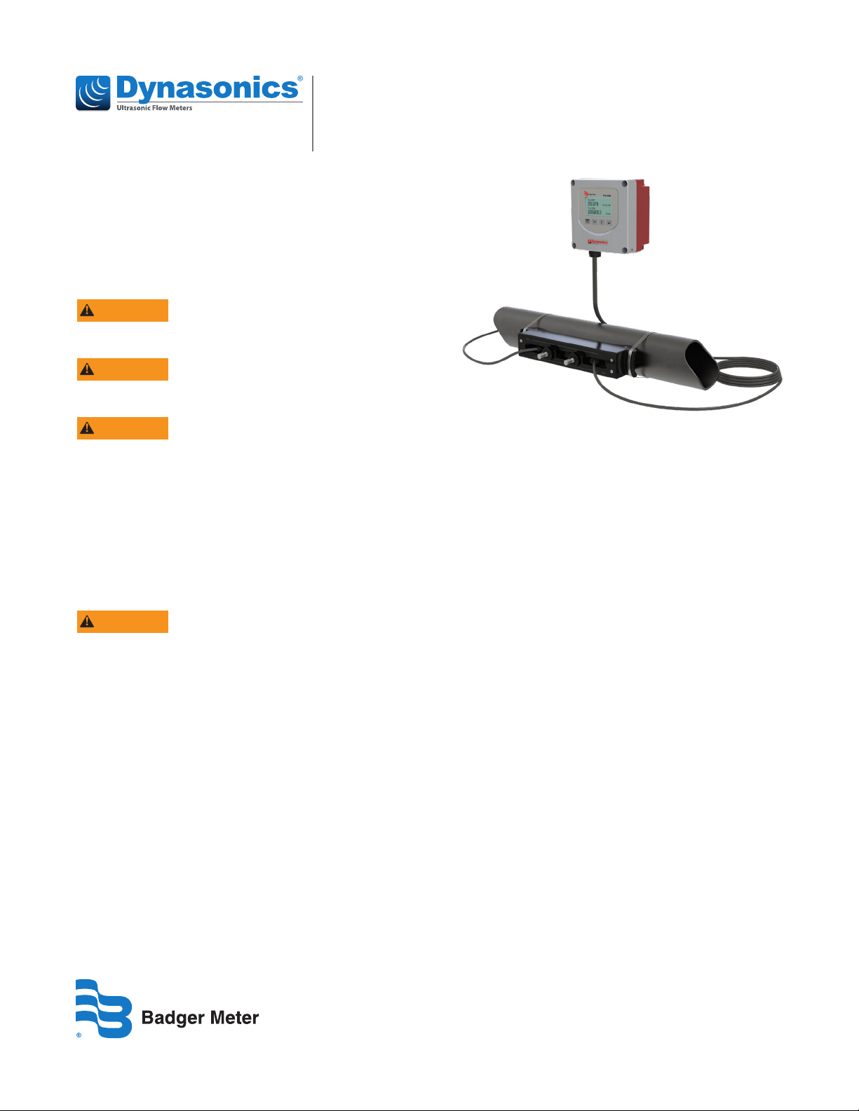
This document explains how to install transit time ultrasonic
transducers with Easy Rail mounting systems.
The Easy Rail mounting system can be installed on vertical
or horizontal pipes. For horizontal applications, install the
system on the side of the pipe.
WARNING
EQUIPMENT SHALL BE PROTECTED FROM UV LIGHT.
WARNING
EQUIPMENT TO BE PROTECTED FROM IMPACT.
WARNING
THIS EQUIPMENT INCLUDES EXTERNAL NON-METALLIC
PARTS. THE USER SHALL THEREFORE ENSURE THAT THE
EQUIPMENT IS NOT INSTALLED IN A LOCATION WHERE IT
MAY BE SUBJECTED TO EXTERNAL CONDITIONS (SUCH AS
HIGH-PRESSURE STEAM) WHICH MIGHT CAUSE A
BUILD-UP OF ELECTROSTATIC CHARGES ON
NON-CONDUCTING SURFACES. ADDITIONALLY, CLEANING
OF THE EQUIPMENT SHOULD BE DONE ONLY WITH A
DAMP CLOTH.
WARNING
DO NOT CONNECT OR DISCONNECT WHEN ENERGIZED.
SPECIFICATIONS
• Voltage: 30V
• Current: 0.375A
• Power: 3.15W
PREINSTALLATION REQUIREMENTS
Program the Meter
Before installing the Easy Rail mounting system, you must
select the optimum transmission mode, enter the site
information, and enter the uid and pipe properties into the
ultrasonic flow meter. For detailed instructions, see the user
manual for your flow meter.
Select a Pipe Location for the Easy Rail
Mounting System
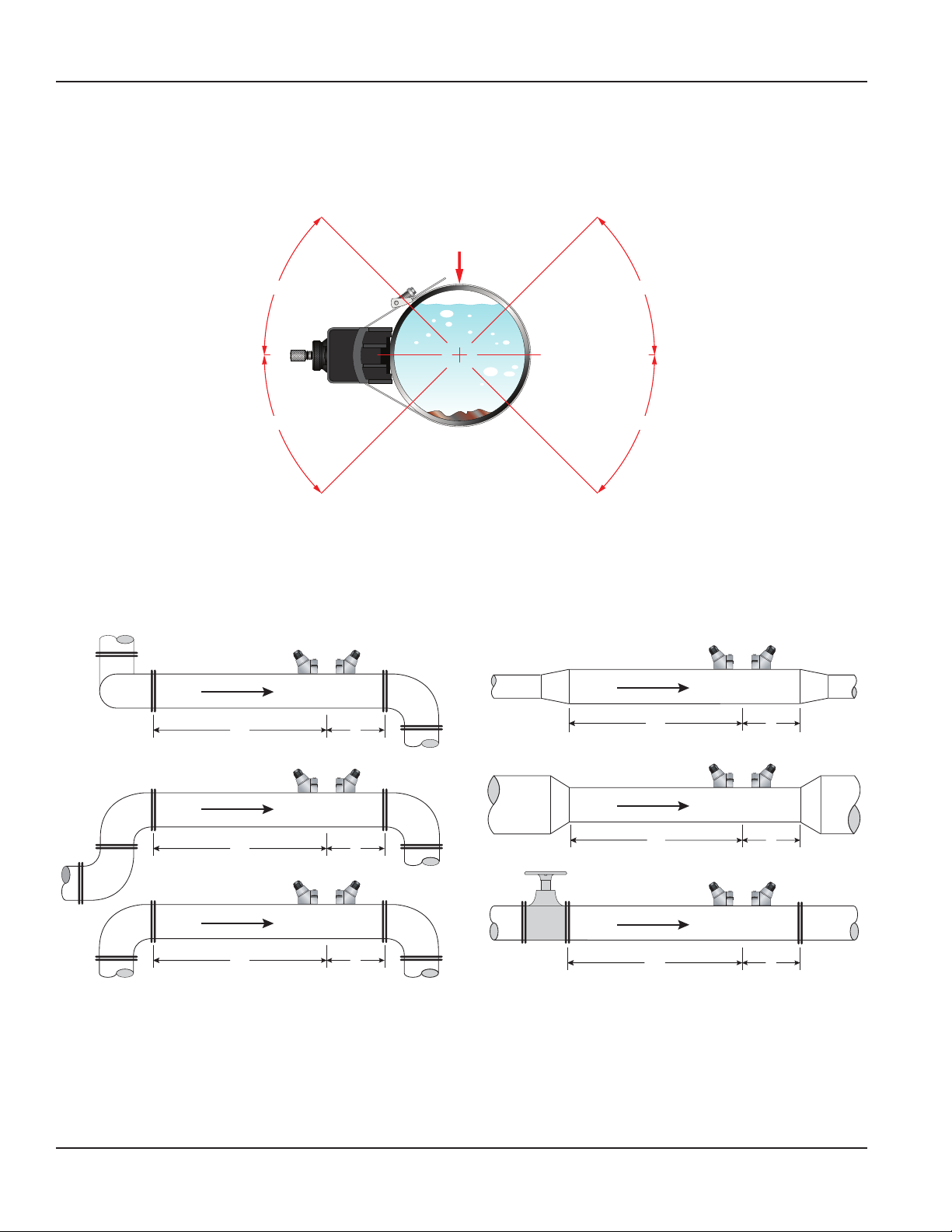
Select a location for the Easy Rail mounting system on a
section of pipe that has at least 10 pipe diameters upstream
of the transducers and 5 pipe diameters downstream. See
“Figure 2: Piping configuration and transducer positioning” on
page2.
For example, if a 3 inch pipe is being measured, the minimum
upstream pipe in front of the mounting rail should be 30 in.
and the minimum downstream pipe behind the transducers
should be at least 15 in.
Pipe runs shorter than the minimums may sometimes be
used with reduced accuracy. There is no way to determine
how much accuracy is sacrificed without doing in-field
testing. For installations where the 10/5 pipe diameters
rule cannot be followed, divide the total length of available
straight pipe into thirds and mount the rail with 2/3 of the
pipe upstream and 1/3 of the pipe downstream.
A full pipe is absolutely essential for making accurate flow
measurements. The flow meter cannot determine if the pipe
is full or not. If the pipe is partially full, the meter will
over-report the amount of flow by the percentage of the pipe
that is not filled with liquid or may not detect any flow.
IND-UM-02650-EN-06 (March 2021)
Installation Guide
Page 2
Pre-Installation Requirements
Install the mounting system in an area where the transducers will not be inadvertently bumped or disturbed.
Avoid installations on downward flowing pipes unless adequate downstream head pressure is present to overcome partial
filling of—or cavitation in—the pipe.
TOP OF
PIPE
45° 45°
YESYES
45° 45°
Figure 1: Transducer positioning
Piping Congurations and Transducer Positioning
Figure 2 shows the number of pipe diameters required downstream and upstream of the transducers for various
piping configurations.
Flow
24 5
Flow
14 5
Flow
10 5
Flow
10 5
Flow
10 5
Flow
24 5
Figure 2: Piping configuration and transducer positioning
The system will provide repeatable measurements on piping systems that do not meet these pipe diameter requirements, but
the accuracy of the readings may be influenced.
Page 2 March 2021IND-UM-02650-EN-06
Page 3
Installation Procedure
INSTALLATION PROCEDURE
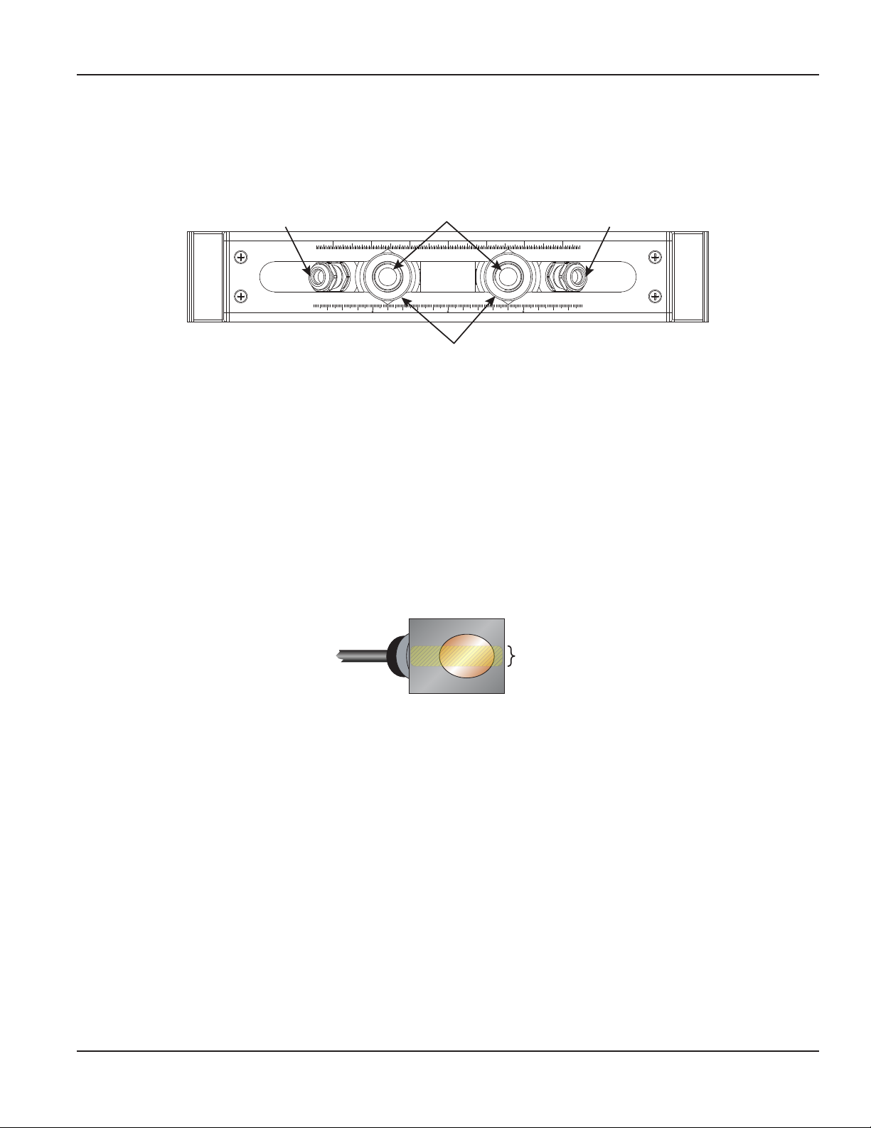
All moving parts are already mounted on the rail. During installation, make sure the rail is firmly positioned on the pipe and all
thumbscrews are hand-tight. See Figure 3.
Transducer Cable
Connector
inch
Transducer Height
Adjustment Thumbcrews
Transducer Position
Adjustment Thumbscrews
Figure 3: Easy rail top view
Transducer Cable
Connector
mm
1. Clean the surface of the pipe. If the pipe has external corrosion or dirt, wire brush, sand or grind the mounting location
until it is smooth and clean. Paint and other coatings, if not aked or bubbled, need not be removed. Plastic pipes typically
do not require surface preparation other than soap and water cleaning.
2. Loosen the position adjustment thumbscrews and slide the transducers along the scale to set the distance between the
them. The top of the rail shows the distance in millimeters and inches.
3. Tighten the position adjustment thumbscrews hand-tight to lock the transducers in place.
4. Apply contact gel to the underside of the transducers.
Place a single bead of couplant, approximately 1/2 inch (12 mm) thick, on the flat face of the transducers. See Figure 4.
Generally, a silicone-based grease is used as an acoustic couplant, but any good quality grease-like substance that is rated
to not ow at the operating temperature of the pipe is acceptable. For pipe surface temperature over 130° F (55° C), use
high-temperature paste (P.N. D002-2011-012) or non-silicone paste (P.N. D002-2011-009).
½ in.
(12 mm)
Figure 4: Transducer bottom view
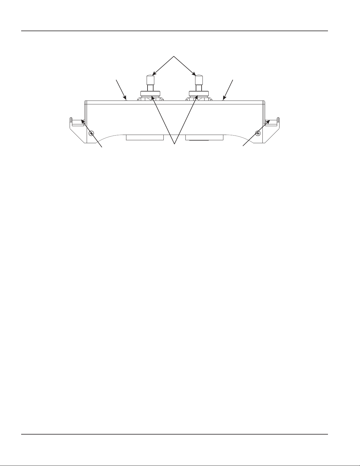
5. Place the mounting rail on the pipe and fasten it with metal banding straps. See Figure 5.
a. Slide the strap into the arched groove on the end of the transducer.
b. Wrap the strap around the pipe.
c. Slide the free end of the strap into the end clip of the strap with the screw at 90 degrees to the strap.
d. Pull the strap through until it loosely fits around the pipe.
e. Rotate the screw so it is parallel to the strap and tighten the screw slightly to help hold the transducer onto the pipe.
Page 3 March 2021 IND-UM-02650-EN-06
Page 4
Installation Procedure
Transducer Height
Adjustment Thumbcrews
Transducer Cable
Connector
Groove for
Metal Banding Strap
Transducer Position
Adjustment Thumbscrews
Figure 5: Easy rail side view
Transducer Cable
Connector
Groove for
Metal Banding Strap
6. Turn the transducer height adjustment thumbscrews clockwise to lower the transducers onto the pipe surface.
7. Verify that the transducer is true to the pipe and adjust as necessary.
8. Tighten the metal banding strap screws enough to hold the mounting rail in place, but not so tight that all of the couplant
squeezes out of the gap between the transducer faces and the pipe.
9. Route the transducer cables back to the ow meter location, avoiding high voltage cable trays and conduits.
Page 4 March 2021IND-UM-02650-EN-06
Page 5
Installation Procedure
Transducer Spacing
Spacing for V-Mount Medium Pipe Transducers on ASME/ANSI Pipes with Potable Water
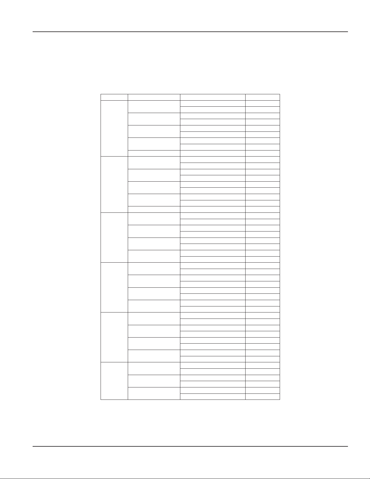
After the mounting path, fluid and pipe properties are entered into the transmitter, the transmitter calculates the proper
transducer spacing. Table 1 lists the transducer spacing for common ASME/ANSI pipe sizes, materials and schedules.
OTE: N JZ transducers accommodate only up to 6 in. pipes.
Pipe Size Pipe Material Schedule Spacing
Schedule 40, Standard 2.83 in.
Schedule 80 2.81 in.
Schedule 40, Standard 3.07 in.
Schedule 80 3.15 in.
Schedule 40, Standard 3.10 in.
Schedule 80 3.18 in.
Schedule 40, Standard 3.03 in.
Schedule 80 3.10 in.
Schedule 40, Standard 3.52 in.
Schedule 80 3.51 in.
Schedule 40, Standard 3.79 in.
Schedule 80 3.89 in.
Schedule 40, Standard 3.81 in.
Schedule 80 3.92 in.
Schedule 40, Standard 3.74 in.
Schedule 80 3.83 in.
Schedule 40, Standard 5.19 in.
Schedule 80 5.17 in.
Schedule 40, Standard 5.50 in.
Schedule 80 5.66 in.
Schedule 40, Standard 5.53 in.
Schedule 80 5.70 in.
Schedule 40, Standard 5.45 in.
Schedule 80 5.58 in.
Schedule 40, Standard 7.00 in.
Schedule 80 6.97 in.
Schedule 40, Standard 7.37 in.
Schedule 80 7.54 in.
Schedule 40, Standard 7.40 in.
Schedule 80 7.58 in.
Schedule 40, Standard 7.31 in.
Schedule 80 7.45 in.
Schedule 40, Standard 8.43 in.
Schedule 80 8.40 in.
Schedule 40, Standard 8.84 in.
Schedule 80 9.07 in.
Schedule 40, Standard 8.88 in.
Schedule 80 9.13 in.
Schedule 40, Standard 8.78 in.
Schedule 80 8.97 in.
Schedule 40, Standard 10.23 in.
Schedule 80 10.53 in.
Schedule 40, Standard 10.27 in.
Schedule 80 10.59 in.
Schedule 40, Standard 10.16 in.
Schedule 80 10.40 in.
3 in.
4 in.
6 in.
8 in.
10 in.
12 in.
CPVC or PVC
Carbon Steel
Stainless 316/316L
Stainless 304
Copper Type K 2.53 in.
CPVC or PVC
Carbon Steel
Stainless 316/316L
Stainless 304
Copper Type K 3.22 in.
CPVC or PVC
Carbon Steel
Stainless 316/316L
Stainless 304
CPVC or PVC
Carbon Steel
Stainless 316/316L
Stainless 304
CPVC or PVC
Carbon Steel
Stainless 316/316L
Stainless 304
Carbon Steel
Stainless 316/316L
Stainless 304
Table 1: Transducer spacing
Page 5 March 2021 IND-UM-02650-EN-06
Page 6

Transit Time Meter, Transducers
INTENTIONAL BLANK PAGE
IND-UM-02650-EN-06Page 6 March 2021
Page 7

INTENTIONAL BLANK PAGE
User Manual
Page 7 March 2021 IND-UM-02650-EN-06
Page 8

Transducers, Easy Rail Mounting System (JZ/KZ)
Control. Manage. Optimize.
Dynasonics is a registered trademark of Badger Meter, Inc. Other trademarks appearing in this document are the property of their respective entities. Due to continuous research,
product improvements and enhancements, Badger Meter reserves the right to change product or system specications without notice, except to the extent an outstanding
contractual obligation exists. © 2021 Badger Meter, Inc. All rights reserved.
www.badgermeter.com
 Loading...