

Page 1
TM
User’s Guide
Shop online at
omega.com
e-mail: [email protected]
For latest product manuals:
www.omegamanual.info
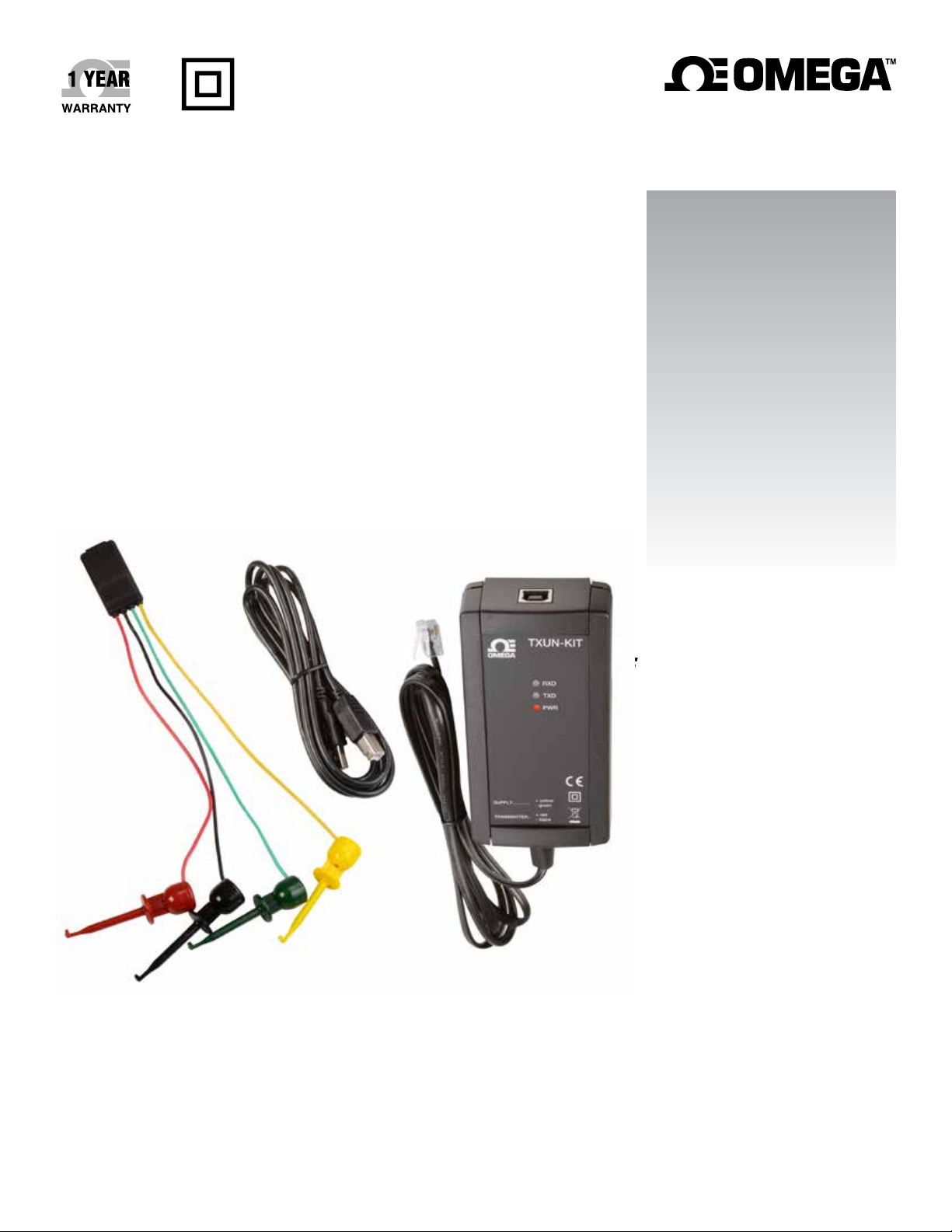
TXUN-KIT
Loop Link USB
Communications Interface
Page 2

omega.com [email protected]
Servicing North America:
U.S.A. Omega Engineering, Inc.
Headquarters: Toll-Free: 1-800-826-6342 (USA & Canada only)
Customer Service: 1-800-622-2378 (USA & Canada only)
Engineering Service: 1-800-872-9436 (USA & Canada only)
Tel: (203) 359-1660 Fax: (203) 359-7700
e-mail: [email protected]
For Other Locations Visit omega.com/worldwide
The information contained in this document is believed to be correct, but OMEGA accepts no liability for any errors it contains, and reserves
the right to alter specifications without notice.
Page 3

Table of
Contents
TXUN-KIT
Table of Contents
Section ........................................................................ Page
Section 1 Warning .......................................................................................... 4
Section 2 Safety instructions ........................................................................ 5
Section 2.1 Symbol Identification ................................................. 5
Section 2.2 Safety Instructions ...................................................... 5
Section 3 Technical Characteristics ............................................................. 7
Section 4 Installation ..................................................................................... 8
Section 4.1 System requirements .................................................. 8
Section 4.2 Installation of Preset ................................................... 8
Section 4.3 Installation from USB ................................................. 8
Section 4.4 Installation from CD-ROM ....................................... 8
Section 5 Preset installation from Windows 7/8/10 ............................ 9-17
Section 5.1 TXUN-KIT installation on Windows 7 .................. 10
Section 5.2 TXUN-KIT installation on Windows 8 .................. 11
Section 6 Troubleshooting on Windows 7 & 8 ......................................... 18
Section 7 TXUN-KIT installation on Windows 10 ............................ 19-23
Section 8 Configuration / Connection ....................................................... 24
Section 8.2 Connection of Omega devices using EZ-Mini ..... 25
Section 8.3 Connection of Omega devices using a modular .. 26
3
Page 4
GENERAL
HAZARD OUS
VOLTAGE
Warning
WARNING
When connected to TXUN Series by the communication cable, this device
can get connected to hazardous electric voltages. Ignoring this warning can
result in severe personal injury or mechanical damage.
To avoid the risk of electric shock and fire, the safety instructions of this manual must be observed and the guidelines followed.
The device must only be applied as described in the following.
Prior to the commissioning of the device, this manual must be examined
carefully.
Only qualified personnel (technicians) should use this device.
If the device is used in a manner not specified by the manufacturer, the protection provided by the device may be impaired.
WARNING
The following operations must only be carried out on a device that is not
connected to TXUN Series and a PC:
Troubleshooting the device.
Repair of the device must be done by Omega electronics A/S only.
1
INSTALLATION
WARNING
The female communication connector of TXUN Series is connected to the
input terminals on which dangerous voltages can occur. It must only be connected to the programming unit TXUN-KIT by way of the attached communication cable.
TXUN-KIT is provided with intrinsically safe galvanic isolation and protective components according to EN60079-11 § 6.2.5 to assure that the safety
components within the connected intrinsically safe devices are protected
against overload.
4
Page 5
2
Safety Instructions
Section 2.1 - Symbol Identification
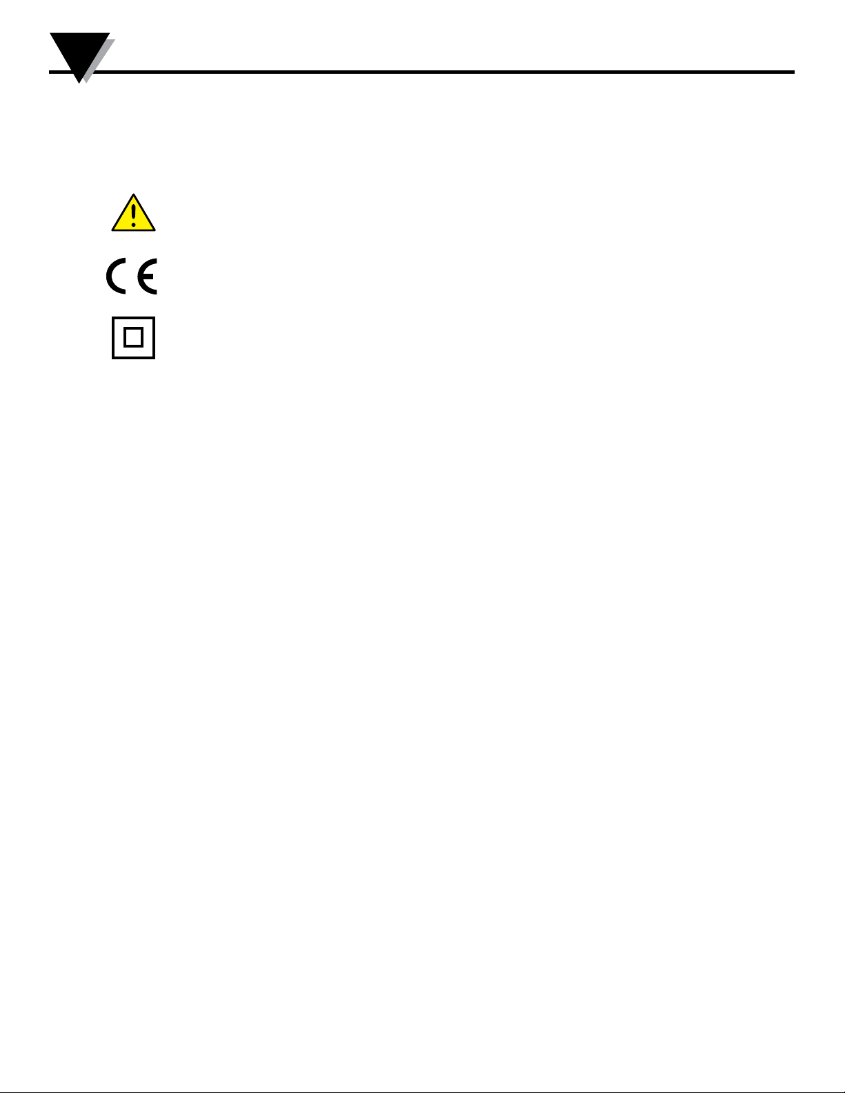
Triangle with an exclamation mark: Warning/demand. Potentially lethal
situations.
The CE mark proves the compliance of the device with the requirements of
the EU directives.
The double insulation symbol shows that the device is protected by double
or reinforced insulation.
Section 2.2 - Safety instructions
Definitions
Hazardous voltages have been defined as the ranges: 75 to 1500 Volt DC, and 50 to 1000 Volt AC.
Technicians are qualified persons educated or trained to mount, operate, and also trouble-shoot technically correct and in
accordance with safety regulations.
Operators, being familiar with the contents of this manual, adjust and operate the knobs or potentiometers during normal
operation.
Receipt and unpacking
Unpack the device without damaging it. The packing should always follow the device until this has been permanently
mounted. Check at the receipt of the device whether the type corresponds to the one ordered.
Environment
Avoid direct sunlight, dust, high temperatures, mechanical vibrations and shock, as well as rain and heavy moisture. If
necessary, heating in excess of the stated limits for ambient temperatures should be avoided by way of ventilation.
All devices fall under Installation Category II, Pollution Degree 1, and Insulation Class II.
Mounting
Only technicians who are familiar with the technical terms, warnings, and instructions in the manual and who are able to
follow these should connect the device.
Should there be any doubt as to the correct handling of the device, please contact your local distributor or, alternatively
5
Page 6

Safety Instructions
PROGRAMMING
During programming, the measuring and connection of external voltages
must be carried out according to the specifications of this manual and the
manual for the unit to be programmed.
The technician must use tools and instruments that are safe to use.
NORMAL OPERATION
Operators are only allowed to adjust and operate devices that are safely
fixed in panels, etc., thus avoiding the danger of personal injury and damage. This means there is no electrical shock hazard, and the device is easily
accessible.
CLEANING
When disconnected, the device may be cleaned with a cloth moistened with
distilled water.
LIABILITY
To the extent that the instructions in this manual are not strictly observed,
the customer cannot advance a demand against Omega electronics A/S that
would otherwise exist according to the concluded sales agreement.
2
6
Page 7

3
Technical characteristics
Section 3 - Technical Characteristics
Programming
During programming, the measuring and connection of external voltages must be carried
out according to the specifications of this manual and the manual for the unit to be programmed.
The technician must use tools and instruments that are safe to use.
Application
Loop Link TXUN-KIT is a USB communications interface for configuration and monitoring of Omega PC-programmable devices. The USB communication is supported by the
Windows versions 7, 8 and 10. Omega devices available in the configuration program
PReset ver. 5.0 or higher, can be programmed by way of Loop Link TXUN-KIT.
Technical characteristics
The PC program CD PReset ver. 5.0 or higher contains the necessary (unsigned) USB
drivers. Loop Link TXUN-KIT is supplied from the USB port of the PC. If you want to
conserve power on a laptop, the USB connector of the TXUN-KIT can be connected to an
externally supplied hub. The communications connector on the Omega devices is
galvanically isolated from the USB connection on the PC.
7
Page 8
Section 4 - Installation
Section 4.1 - System requirements
Windows 7, 8 or 10 with the following recommendations:
Processor > 1 GHz
Memory 1 GB RAM (32-bit) or 2 GB RAM (64-bit)
Hard disk space 16 GB (32-bit) or 20 GB (64-bit)
N.B.: Loop Link TXUN-KIT devices with serial no. <059999999 are NOT compatible
with Windows 7, 8 and 10.
Section 4.2 - Installation of Preset
The USB communications interface Loop Link TXUN-KIT must not be connected to
the USB port of the PC until after installation of the PReset program.
PReset will be installed on your hard disk and the registry will be updated with all
necessary information on the program. A PReset icon will automatically be placed
on the desk top.
Installation
4
Section 4.3 - Installation from CD-ROM
1. Insert the CD-ROM in the CD-ROM drive and the dialog ”InstallShield
Wizard PReset - INSTALL” will start automatically.
2. When the installation program has been started, on-screen guidelines will
guide you through the rest of the installation.
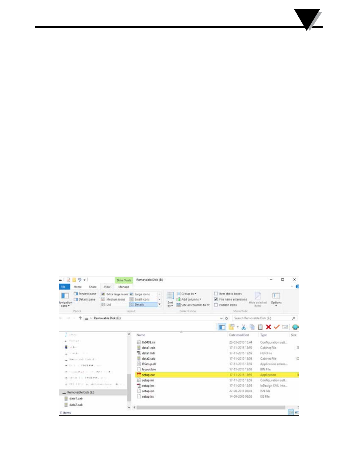
Section 4.4 - Installation from USB
1. Plug in the USB.
3. Open File Explorer and locate the USB drive. Double-click on the file “setup.
exe”’ to start the installation.
8
Page 9
5
Preset Installation on Windows 7 / 8 / 10
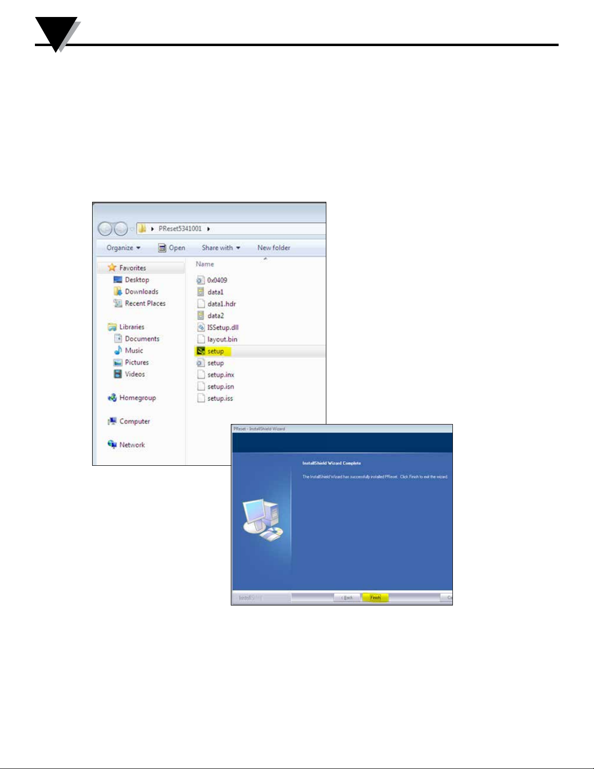
Section 5 - PReset installation on Windows 7 / 8 / 10
To install PReset on Windows 7 / Windows 8 / Windows 10 it is necessary to be a
local administrator on the PC.
Install from the CD or the USB or download the software from
www.prelectronics.com
Run setup and follow the instructions on the screen.
9
Page 10
Preset Installation on Windows 7 / 8 / 10
Section 5.1 - TXUN-KIT installation on Windows 7
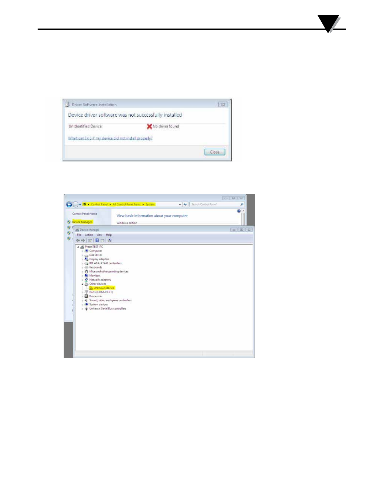
To install TXUN-KIT on Windows 7 it is necessary to be a local administrator on the pc.
1. Connect your TXUN-KIT to a USB port on your machine.
2. Click [Close] in the following dialog:
3. Go to Windows control panel and click [System] and then [Device manager].
5
4. Right click the [Unknown device] and click [Update driver software].
10
Page 11
5
Preset Installation on Windows 7 / 8 / 10
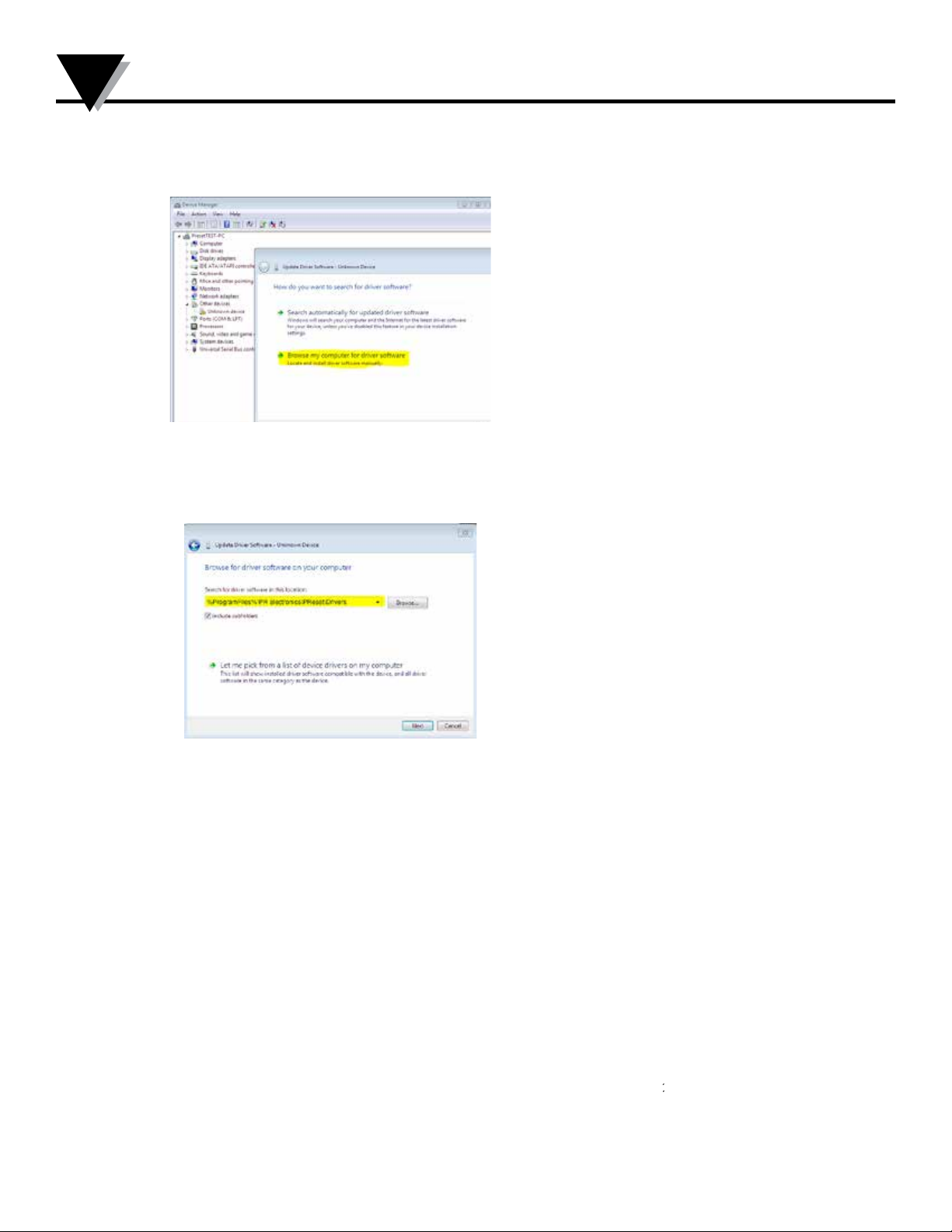
5. Click [Browse my Computer for driver software].
6. OMeset path
11
Page 12
Preset Installation on Windows 7 / 8 / 10
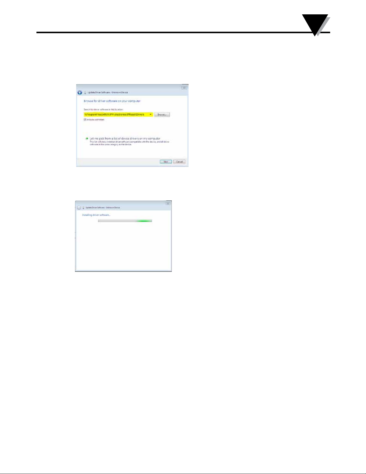
OMeset path
7. Click [Next].
8. Now the driver for your TXUN-KIT will be installed.
5
12
Page 13
5
Preset Installation on Windows 7 / 8 / 10
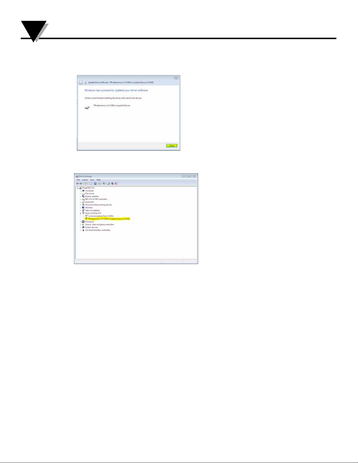
9. When you see this screen click [Close].
10. The installation of TXUN-KIT driver is
complete!
13
Page 14
Preset Installation on Windows 7 / 8 / 10
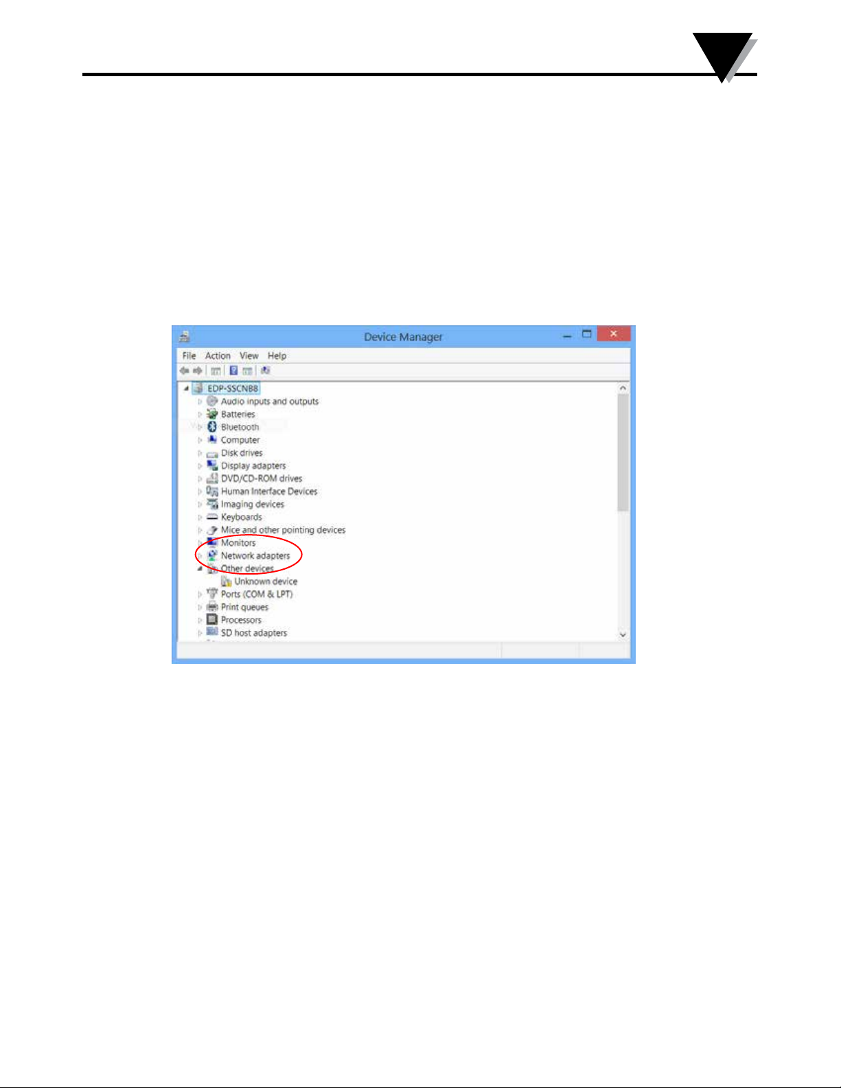
Section 5.2 - OMeset installation on Windows 8
To install TXUN-KIT on Windows 8 it is necessary to be a local administrator on the pc.
1. Connect your TXUN-KIT to a USB port on your machine.
Go to Windows control panel and click [System] and then [Device
manager].
2. Right click the [Unknown device] and click [Update driver software].
5
14
Page 15
5
Preset Installation on Windows 7 / 8 / 10
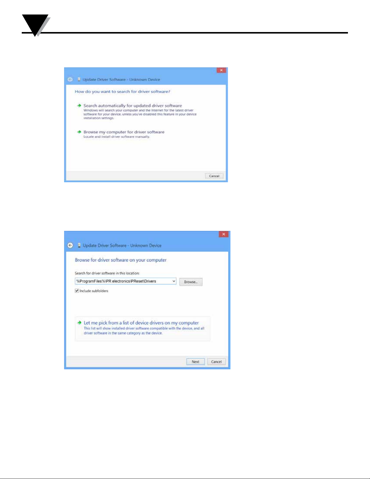
3. Click [Browse my Computer for driver software].
4. OMeset path
15
Page 16
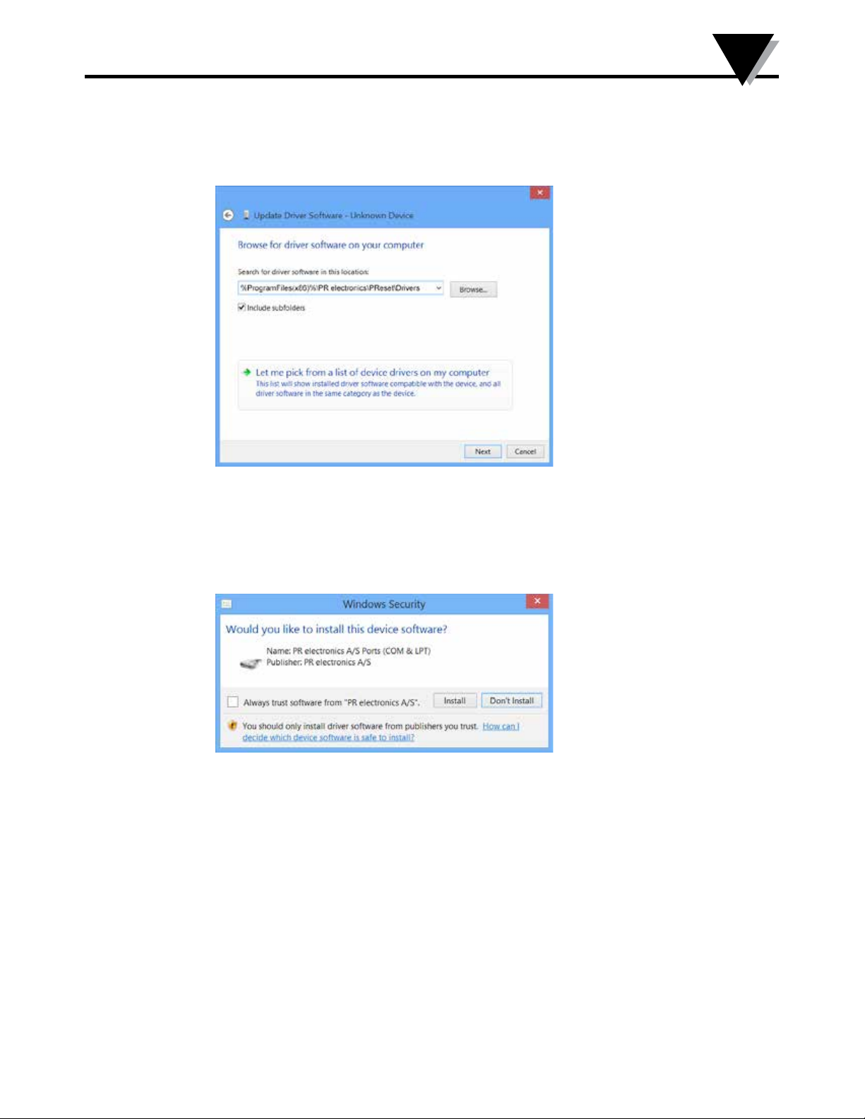
OMeset path
Preset Installation on Windows 7 / 8 / 10
5
5. Click [Next].
6. Click [Install]. Now the driver for your TXUN-KIT will be
installed.
16
Page 17
5
Preset Installation on Windows 7 / 8 / 10
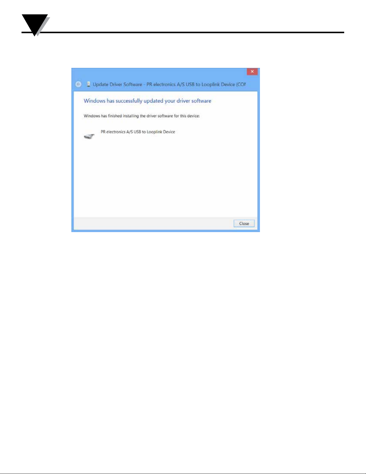
7. When you see this screen click [Close]. The installation of TXUN-KIT driver is
complete!
17
Page 18
Troubleshooting for Windows 7 & 8
Section 6 - Troubleshooting for Windows 7 & 8
If you are unable to install the USB Loop Link follow these steps:
1. Disconnect the TXUN-KIT.
2. Go to the Control Panel.
3. Go to Devices and Printers.
4. Locate your PC (under devices).
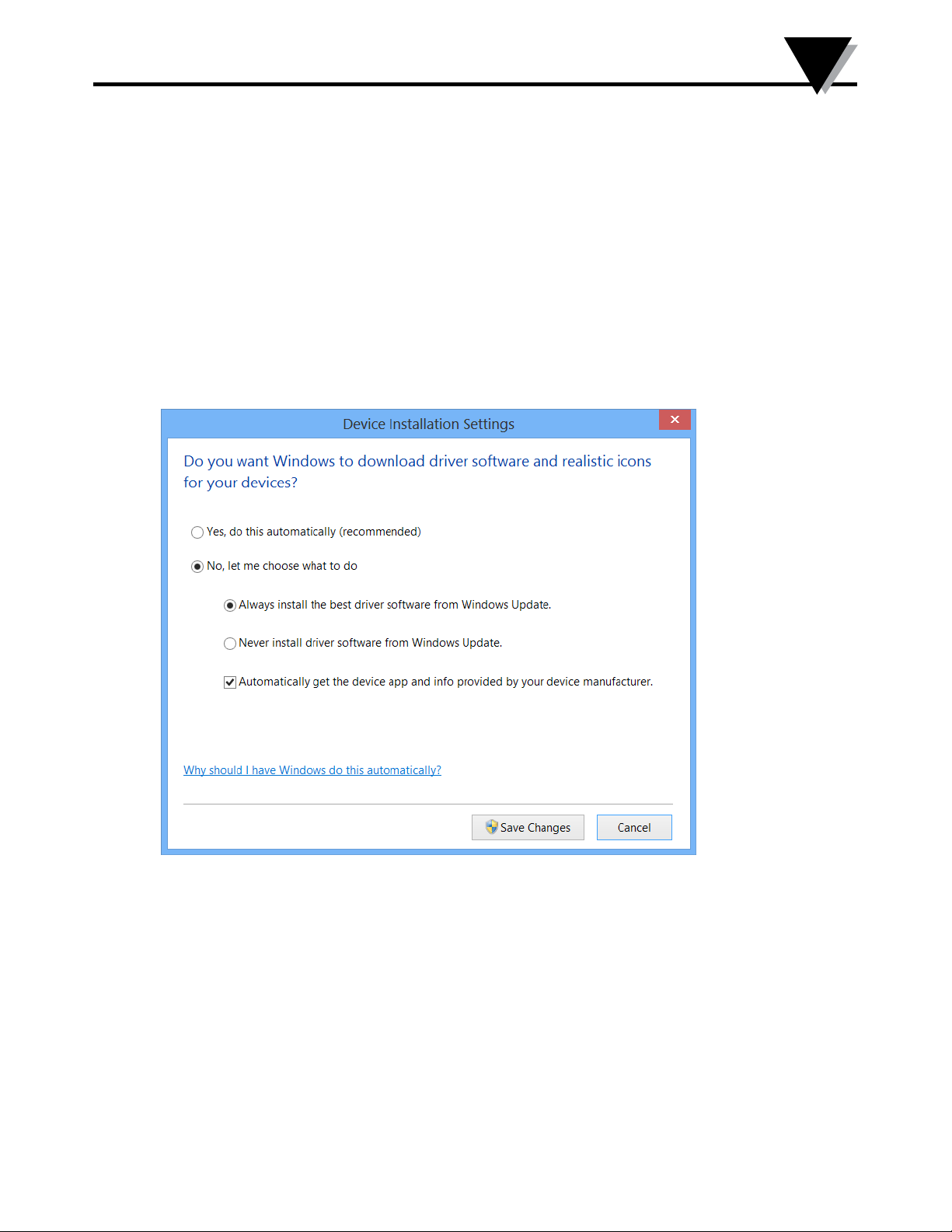
5. Right click on your PC and choose “Devise installation settings”.
6. Allow Windows to “Always install the best driver software from
Windows update”.
7. Make sure you are connected to the internet.
8. Reconnect the TXUN-KIT.
6
18
Page 19
7
TXUN-KIT Installation on Window 10
Section 7 - TXUN-KIT
To install TXUN-KIT on Windows 10 it is necessary to be a local administrator on the
pc.
1. Connect your TXUN-KIT to a USB port on your machine.
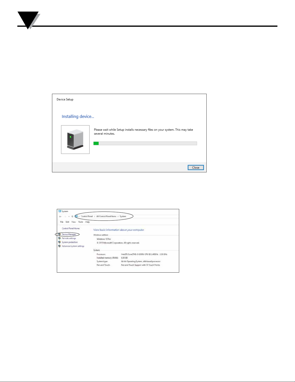
2. Windows 10 will automatically start the installation process.
3. Go to Windows control panel and click [System] and then
[Device manager].
19
Page 20
TXUN-KIT Installation on Window 10
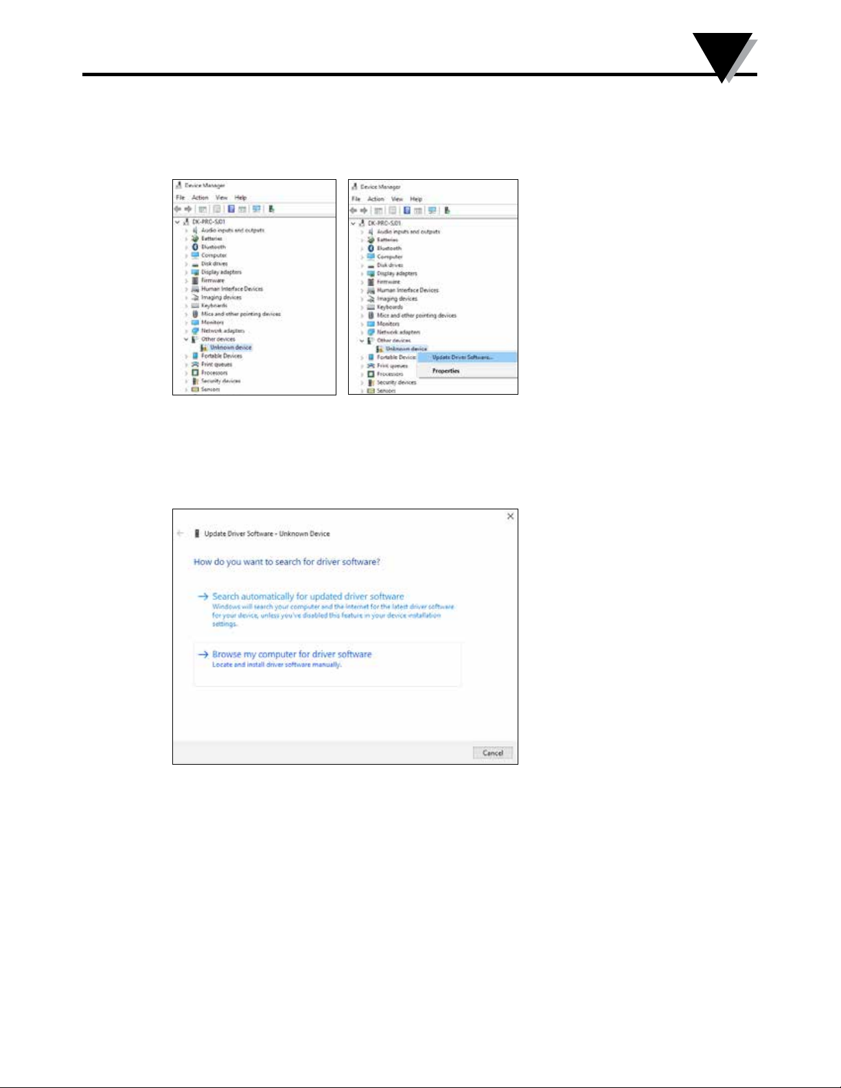
4. Right click the [Unknown device] and click [Update driver software].
7
5. Click [Browse my Computer for driver software].
20
Page 21
7
TXUN-KIT Installation on Window 10
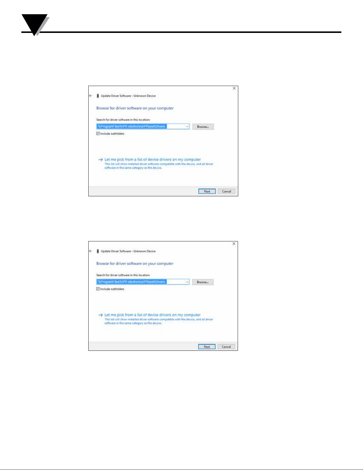
6. OMeset path
OMeset path
7. Click [Next].
21
Page 22
TXUN-KIT Installation on Window 10
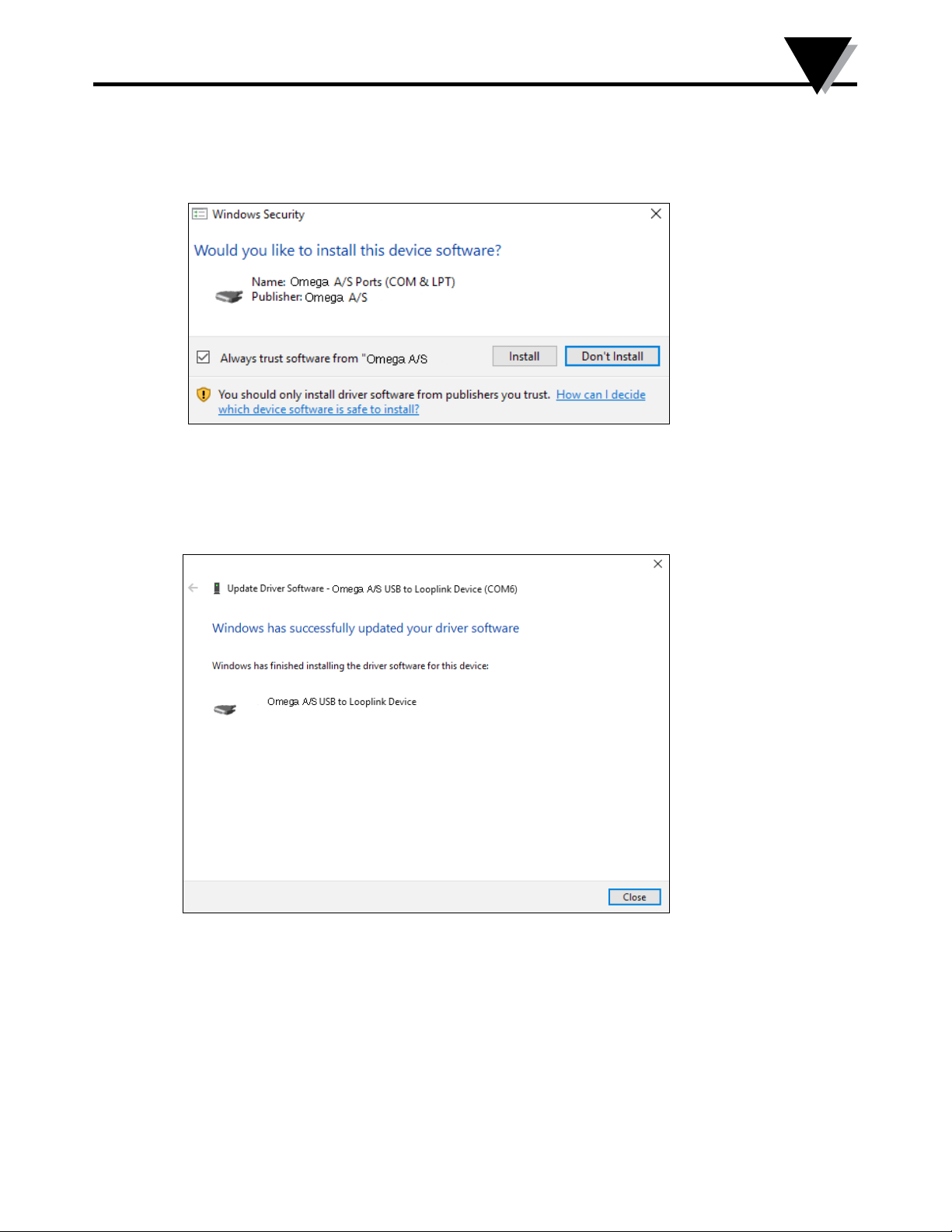
8. Click [Install]. Now the driver for your TXUN-KIT will be installed.
9. When you see this screen click [Close]. The installation of the
TXUN-KIT driver is complete!
7
22
Page 23
7
TXUN-KIT Installation on Window 10
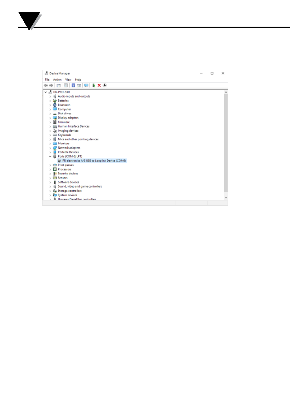
10. You can now see the TXUN-KIT USB to Loop Link device in the Device Manager.
23
Page 24
Configuration/Connection
8
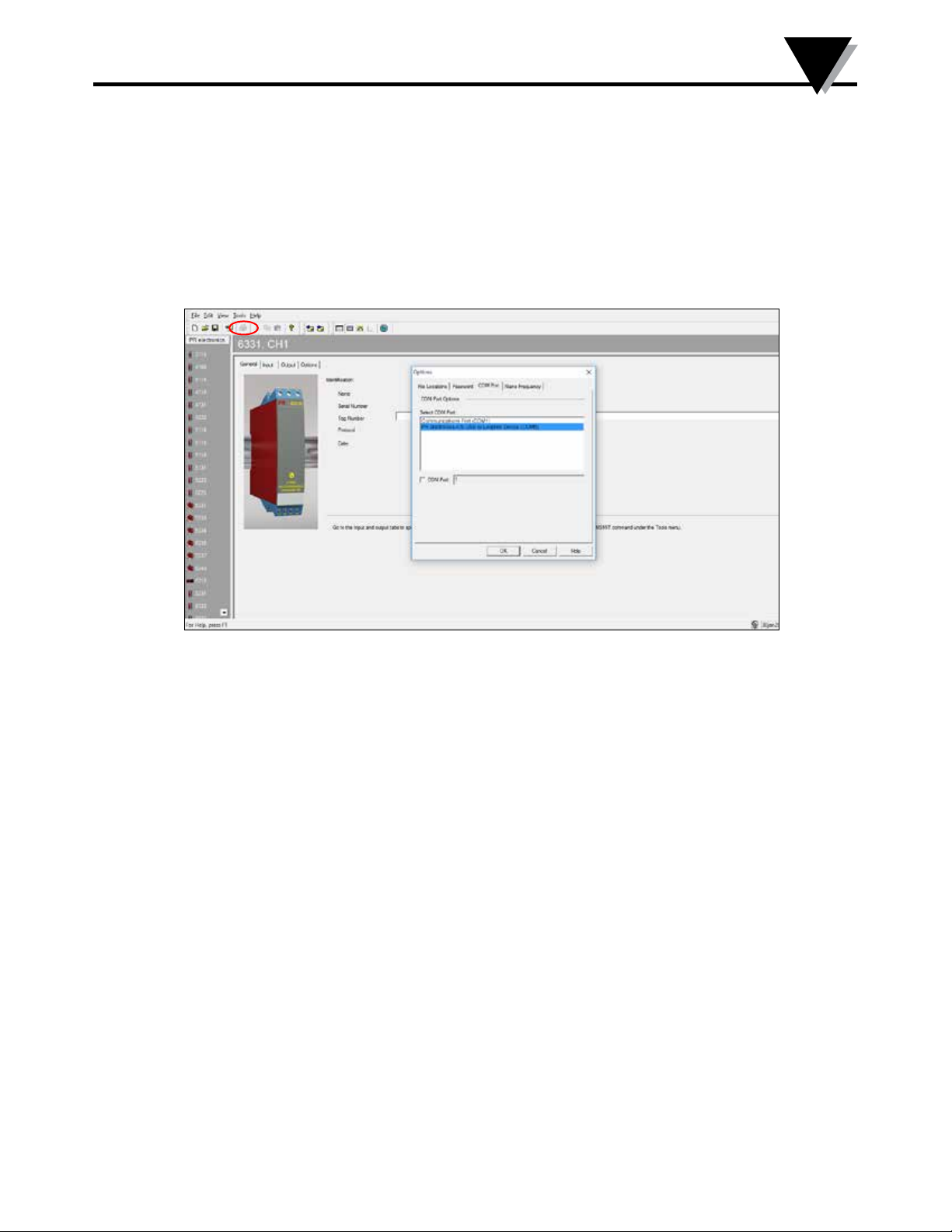
Section 8.1 - Configuration of USB Communication in Preset
1. Start the OMeset program and choose [Tools] [Select COM port], and the
”Options” window is shown on screen.
2. Select Omega Loop Link. Click OK.
3. If you want to configure Loop Link for other USB ports, you must connect
Loop Link to these ports and install the USB drivers for each port.
24
Page 25
8
Configuration/Connection
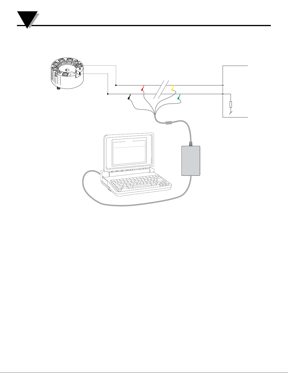
Section 8.2 - Configuration of USB Communication in Preset
TXUN Series
1
2
Disconnect
Receiving
Equipment
+Vsupply
Red
Black
Connector
Yellow
*
Green
*
Input
* Connected only for
on-line programming
l
i
F
:
e
t
a
D
l
n
a
i
r
e
S
:
o
n
g
a
T
g
o
l
a
n
A
y
t
t
u
p
n
I
a
r
t
u
p
n
I
c
e
n
n
o
C
n
u
j
d
l
o
C
n
o
p
s
e
R
1
3
3
5
p
o
t
e
R
P
0
1
-
-
8
4
0
0
2
4
9
5
1
0
2
3
4
0
:
o
s
i
c
n
o
r
t
c
l
e
e
R
P
t
u
p
n
i
:
e
p
:
e
g
n
:
n
i
o
t
:
p
m
o
c
n
i
o
t
c
:
e
i
m
t
e
s
t
u
p
t
u
o
g
o
l
a
n
A
A
m
0
2
-
4
:
e
p
y
t
t
u
p
t
u
O
C
E
/
I
I
N
D
0
0
1
t
P
0
.
0
5
-
0
0
.
0
e
r
i
w
-
3
-
-
-
-
-
c
e
s
0
0
.
1
l
e
a
c
s
p
U
:
r
o
r
r
e
r
o
s
n
e
S
C
0
L o op
0
0
:
0
3
:
8
0
n
o
t
i
p
O
e
g
a
u
g
n
a
L
n
o
i
t
a
c
i
n
u
m
m
o
C
t
u
t
p
u
O
t
u
p
n
I
t
c
u
d
o
r
P
e
L i nk
USB cable
25
Page 26
Configuration/Connection
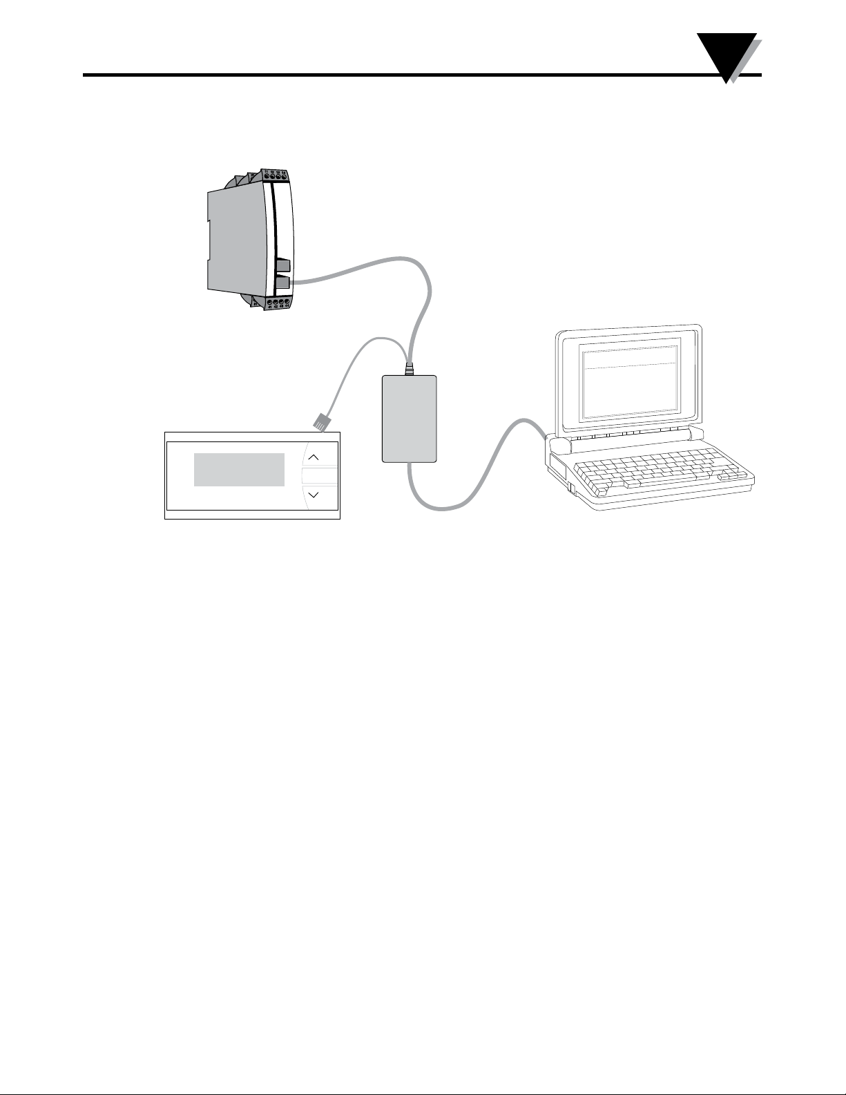
Programming cable
with modular connector
11
USB cable
26
Page 27

WARRANTY/DISCLAIMER
OMEGA ENGINEERING, INC. warrants this unit to be free of defects in materials and workmanship for a
period of 13 months from date of purchase. OMEGA’s WARRANTY adds an additional one (1) month grace
period to the normal one (1) year product warranty to cover handling and shipping time. This ensures
that OMEGA’s customers receive maximum coverage on each product.
If the unit malfunctions, it must be returned to the factory for evaluation. OMEGA’s Customer Service
Department will issue an Authorized Return (AR) number immediately upon phone or written request.
Upon examination by OMEGA, if the unit is found to be defective, it will be repaired or replaced at no
charge. OMEGA’s WARRANTY does not apply to defects resulting from any action of the purchaser,
including but not limited to mishandling, improper interfacing, operation outside of design limits,
improper repair, or unauthorized modification. This WARRANTY is VOID if the unit shows evidence of
having been tampered with or shows evidence of having been damaged as a result of excessive corrosion;
or current, heat, moisture or vibration; improper specification; misapplication; misuse or other operating
conditions outside of OMEGA’s control. Components in which wear is not warranted, include but are not
limited to contact points, fuses, and triacs.
OMEGA is pleased to offer suggestions on the use of its various products. However,
OMEGA neither assumes responsibility for any omissions or errors nor assumes liability for
any damages that result from the use of its products in accordance with information provided
by OMEGA, either verbal or written. OMEGA warrants only that the parts manufactured by the
company will be as specified and free of defects. OMEGA MAKES NO OTHER WARRANTIES OR
REPRESENTATIONS OF ANY KIND WHATSOEVER, EXPRESSED OR IMPLIED, EXCEPT THAT OF
TITLE, AND ALL IMPLIED WARRANTIES INCLUDING ANY WARRANTY OF MERCHANTABILITY
AND FITNESS FOR A PARTICULAR PURPOSE ARE HEREBY DISCLAIMED. LIMITATION OF
LIABILITY: The remedies of purchaser set forth herein are exclusive, and the total liability of
OMEGA with respect to this order, whether based on contract, warranty, negligence,
indemnification, strict liability or otherwise, shall not exceed the purchase price of the
component upon which liability is based. In no event shall OMEGA be liable for
consequential, incidental or special damages.
CONDITIONS: Equipment sold by OMEGA is not intended to be used, nor shall it be used: (1) as a “Basic
Component” under 10 CFR 21 (NRC), used in or with any nuclear installation or activity; or (2) in medical
applications or used on humans. Should any Product(s) be used in or with any nuclear installation or
activity, medical application, used on humans, or misused in any way, OMEGA assumes no responsibility
as set forth in our basic WARRANTY/DISCLAIMER language, and, additionally, purchaser will indemnify
OMEGA and hold OMEGA harmless from any liability or damage whatsoever arising out of the use of the
Product(s) in such a manner.
RETURN REQUESTS/INQUIRIES
Direct all warranty and repair requests/inquiries to the OMEGA Customer Service Department. BEFORE
RETURNING ANY PRODUCT(S) TO OMEGA, PURCHASER MUST OBTAIN AN AUTHORIZED RETURN (AR)
NUMBER FROM OMEGA’S CUSTOMER SERVICE DEPARTMENT (IN ORDER TO AVOID PROCESSING
DELAYS). The assigned AR number should then be marked on the outside of the return package and on any
correspondence.
The purchaser is responsible for shipping charges, freight, insurance and proper packaging to prevent
breakage in transit.
FOR WARRANTY RETURNS, please have the
following information available BEFORE contacting
OMEGA:
1. Purchase Order number under which the product
was PURCHASED,
2. Model and serial number of the product under
warranty, and
3. Repair instructions and/or specific problems
relative to the product.
OMEGA’s policy is to make running changes, not model changes, whenever an improvement is possible. This affords our
customers the latest in technology and engineering.
OMEGA is a trademark of OMEGA ENGINEERING, INC.
© Copyright 2018 OMEGA ENGINEERING, INC. All rights reserved. This document may not be copied, photocopied,
reproduced, translated, or reduced to any electronic medium or machine-readable form, in whole or in part, without the prior
written consent of OMEGA ENGINEERING, INC.
FOR NON-WARRANTY REPAIRS, consult
OMEGA for current repair charges. Have
the following information available BEFORE
contacting OMEGA:
1. Purchase Order number to cover the COST
of the repair,
2. Model and serial number of the product, and
3. Repair instructions and/or specific problems
relative to the product.
Page 28

Where Do I Find Everything I Need for
Process Measurement and Control?
OMEGA…Of Course!
Shop online at omega.com
TEMPERATURE
MU
Thermocouple, RTD & Thermistor Probes, Connectors,
Panels & Assemblies
MU
Wire: Thermocouple, RTD & Thermistor
MU
Calibrators & Ice Point References
MU
Recorders, Controllers & Process Monitors
MU
Infrared Pyrometers
PRESSURE, STRAIN AND FORCE
MU
Transducers & Strain Gages
MU
Load Cells & Pressure Gages
MU
Displacement Transducers
MU
Instrumentation & Accessories
FLOW/LEVEL
MU
Rotameters, Gas Mass Flowmeters & Flow Computers
MU
Air Velocity Indicators
MU
Turbine/Paddlewheel Systems
MU
Totalizers & Batch Controllers
pH/CONDUCTIVITY
MU
pH Electrodes, Testers & Accessories
MU
Benchtop/Laboratory Meters
MU
Controllers, Calibrators, Simulators & Pumps
MU
Industrial pH & Conductivity Equipment
DATA ACQUISITION
MU
Communications-Based Acquisition Systems
MU
Data Logging Systems
MU
Wireless Sensors, Transmitters, & Receivers
MU
Signal Conditioners
MU
Data Acquisition Software
HEATERS
MU
Heating Cable
MU
Cartridge & Strip Heaters
MU
Immersion & Band Heaters
MU
Flexible Heaters
MU
Laboratory Heaters
ENVIRONMENTAL
MONITORING AND CONTROL
MU
Metering & Control Instrumentation
MU
Refractometers
MU
Pumps & Tubing
MU
Air, Soil & Water Monitors
MU
Industrial Water & Wastewater Treatment
MU
pH, Conductivity & Dissolved Oxygen Instruments
M5697/1018
 Loading...