

Page 1
TM
User’s Guide
Shop online at
omega.com
e-mail: [email protected]
For latest product manuals:
www.omegamanual.info
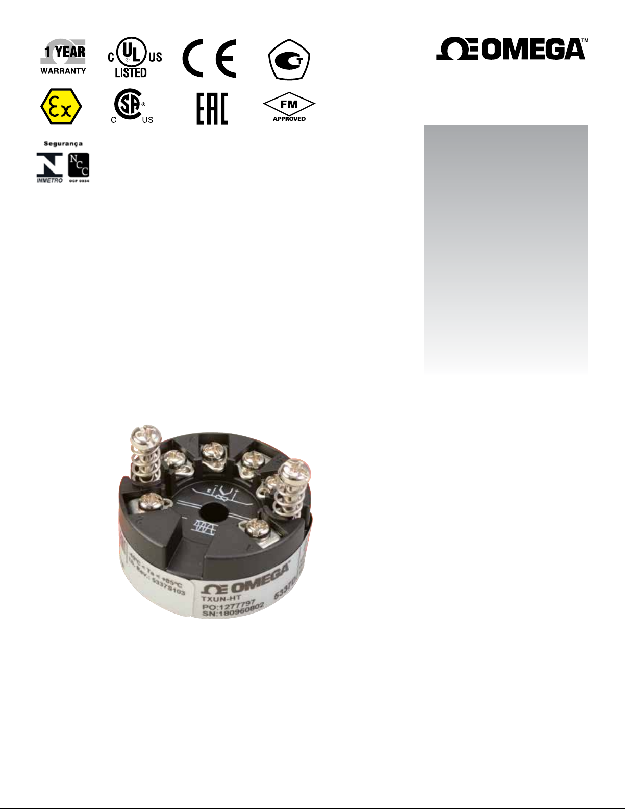
TXUN-HT
2 Wire Transmitter
with Hart Protocol
Page 2

omega.com [email protected]
Servicing North America:
U.S.A. Omega Engineering, Inc.
Headquarters: Toll-Free: 1-800-826-6342 (USA & Canada only)
Customer Service: 1-800-622-2378 (USA & Canada only)
Engineering Service: 1-800-872-9436 (USA & Canada only)
Tel: (203) 359-1660 Fax: (203) 359-7700
e-mail: [email protected]
For Other Locations Visit omega.com/worldwide
The information contained in this document is believed to be correct, but OMEGA accepts no liability for any errors it contains, and reserves
the right to alter specifications without notice.
Page 3

Table of
Contents
TXUN-HT
Table of Contents
Section ........................................................................ Page
Section 1 Application ..................................................................................... 4
Section 2 Technical Characteristics ............................................................. 5
Section 3 Application cont. ........................................................................... 6
Section 4 Ordering Codes for TXUN-HT ................................................... 7
Section 5 Technical Data ......................................................................... 8-10
Section 6 Changing the Hart protocol version .................................. 11-13
Section 6.2 Loop links ............................................................................... 12
Section 7 Connections ................................................................................. 14
Section 8 Block Diagram .............................................................................. 15
Section 9 Programming ........................................................................ 16-17
Section 10 Connection of transmitters in multidrop mode .................... 18
Section 10.1 Mechanical specifications ................................................... 18
Section 10.2 Mounting of sensor wires .................................................. 18
Section 11 Appendix ...................................................................................... 19
3
Page 4

Application
Section 1 - 2 Wire Programmable Transmitter TXUN-HT
• RTD, TC, Ohm, or mV input
• 2 analogue inputs and 5 device variables with status
available
• HART® protocol revision selectable from HART® 5
or HART® 7
• Hardware assessed for use in SIL applications
• Mounting on a DIN rail in safe area or hazardous gas
and dust area
Application
• Linearised temperature measurement with TC and RTD sensors e.g. Pt100 and Ni100.
• HART® communication and 4 to 20 mA analogue PV output for individual, difference or average temperature
measurement of up to two RTD or TC
input sensors.
1
• Conversion of linear resistance to a standard analogue current signal, e.g from valves or Ohmic level sensors.
• Amplification of bipolar mV signals to standard 4 to 20 mA current signals.
• Up to 63 transmitters (HART® 7) can be connected in a multidrop communication setup.
4
Page 5

2
Technical Characteristics
Section 2 - Technical Characteristics
• HART® protocol revision can be changed by user configuration to either HART® 5 or HART® 7 protocol.
• The HART® 7 protocol offers:
• Long Tag numbers of up to 32 characters.
- Enhanced Burst Mode and Event notification with time stamping.
- Device variable and status mapping to any dynamic variable PV, SV, TV or QV.
- Process signal trend measurement with logs and summary data.
- Automatic event notification with time stamps.
- Command aggregation for higher communication efficiency.
• TXUN-HT is designed according to strict safety requirements and is therefore suitable for applications in SIL
installations.
• Continuous check of vital stored data.
• Meeting the NAMUR NE21 recommendations, the TXUN-HT HART® transmitter ensures top measurement
performance in harsh EMC environments. Additionally, the TXUN-HT meets NAMUR NE43 and NE89
recommendations.
Mounting / installation / programming
• For DIN form B sensor head or DIN rail mounting.
• Configuration via standard HART® communication interfaces or by TXUN-KIT.
5
Page 6
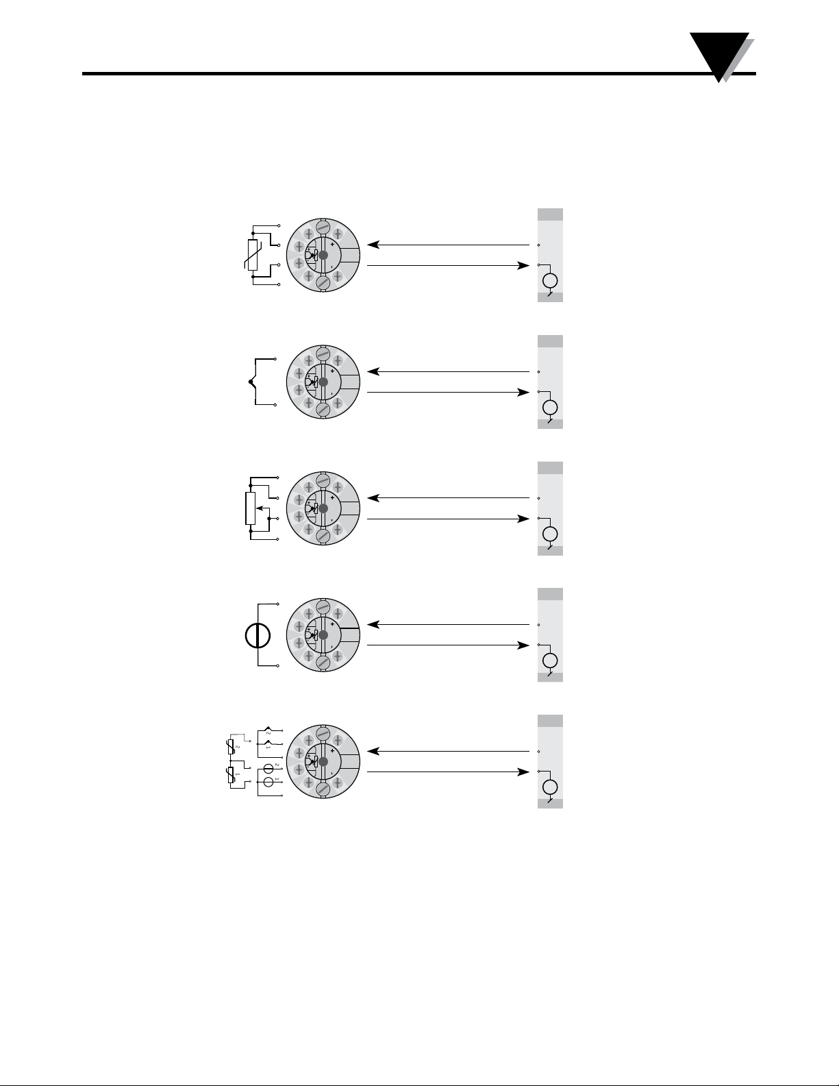
Section 3 - Applications cont.
RTD to 4...20 mA
+
+
-
-
Applications Cont.
2-wire installation
in control room
V+
mA
3
TC to 4...20 mA
+
-
+
+
-
-
Resistance to 4...20 mA
+
+
-
-
mV to 4...20 mA
+
+
+
-
-
-
Dierence or average
RTD, TC or mV
2
+-
2
1
+-
2
+-
1
1
+-
+
+
-
-
2-wire installation
in control room
V+
mA
2-wire installation
in control room
V+
mA
2-wire installation
in control room
V+
mA
2-wire installation
in control room
V+
mA
6
Page 7

4
Ordering Codes for TXUN-HT
Section 4 - Ordering codes for TXUN-HT
Type Version
TXUN-HT
Standard ................ . . . . . . . . . . . . .: A
CSA, FM, ATEX, IECEx & INMETRO. . . . : D
Section 4.2 - Accessories
TXUN-KIT = Loop Link USB interface and OMset Software
Section 4.3 - Technical data
Environmental conditions:
Specifications range ....................... -40 to 85°C
Calibration temperature ................ 20 to 28°C
Relative humidity ........................... < 95% RH (non-cond.)
Protection degree (encl./terminal) IP68/IP00
Mechanical specifications:
Dimensions .................................... Ø 44 x 20.2 mm
Weight approx. ............................... 50 g
Max. wire size ................................. 1 x1.5 mm2 stranded wire
Screw terminal torque ................... 0.4 Nm
Vibration .......................................... IEC 60068-2-6 : 2007
2...25 Hz ........................................ ±1.6 mm
25...100 Hz .................................... ±4 g
Common electrical specifications:
Supply voltage, DC:
Standard ....................................... 8.0...35 V
ATEX, CSA, FM, IECEx & INMETRO 8.0...30 V
Voltage drop ................................... 8.0 V
Isolation - test / working .............. 1.5 kVAC / 50 VAC
Signal / noise ratio ......................... > 60 dB
Communications interface ............ Loop Link & HART®
Response time (programmable).. . . 1...60 s
7
Page 8

Section 5 - Technical Data
Accuracy, the greater of general and basic values:
Input type
All ≤ ±0.05% of span ≤ ±0.005% of span / °C
Input type
Pt50 - Pt1000
Ni50 - Ni1000
Lin. R
Volt
Absolute
accuracy
Basic
accuracy
≤ ±0.1°C ≤ ±0.005°C/°C
≤ ±0.2°C ≤ ±0.005°C/°C
≤ ±0.1 Ω ≤ ±5 mW / °C
≤ ±10 µV ≤ ±0.5 µV / °C
General values
Basic values
Temperature
coefficient
Temperature
coefficient
Technical Data
5
TC type:
E, J, K, L, N, T, U
TC type:
1
, Lr, R, S, W3, W5
B
TC type:B
TC type:B
TC type:B
TC
TC
TC B
TC B
2
3
4
B1 accuracy specification range > 400°C
2
B
accuracy specification range > 160°C < 400°C
3
accuracy specification range > 85°C < 160°C
4
accuracy specification range < 85°C
≤ ±0.5°C
≤ ±1°C
≤ ±3°C ≤ ±0.3°C / °C
≤ ±8°C ≤ ±0.8°C / °C
not specified not specified
≤ ±0.025°C / °C
≤ ±0.1°C / °C
TC cold junction compensation ... < ±1.0°C
Max. offset on input signal ........... 50% of selec. max. value
EMC immunity influence .................... < ±0.1% of span
Extended EMC immunity:
NAMUR NE 21, A criterion, burst ..... < ±1% of span
8
Page 9

5
Technical Data
Section 5.2 - Input specifications:
RTD input types:
RTD
type
Pt100
Ni100
Lin. R
Min.
value
-200°C
-60°C
0 W
Max.
values
+850°C
+250°C
7000 W
Min.
span
10°C
10°C
25 W
Standard
IEC 60751
DIN 43760
-----
Pt50, Pt100, Pt200, Pt500, Pt1000, Ni50, Ni100, Ni120, Ni1000
Cable resistance per wire (max.) .. 5 Ω
(up to 50 Ω per wire is possible with reduced measurement accuracy)
Sensor current ................................. Nom. 0.2 mA
Type
B
E
J
K
L
Lr
N
R
S
T
U
W3
W5
Min.
temperature
0°C
-100°C
-100°C
-180°C
-200°C
-200°C
-180°C
-50°C
-50°C
-200°C
-200°C
0°C
0°C
Max.
temperature
+1820°C
+1000°C
+1200°C
+1372°C
+900°C
+800°C
+1300°C
+1760°C
+1760°C
+400°C
+600°C
+2300°C
+2300°C
Min.
span
100°C
50°C
50°C
50°C
50°C
50°C
50°C
100°C
100°C
50°C
50°C
100°C
100°C
Standard
IEC584
IEC584
IEC584
IEC584
DIN 43710
GOST 3044-84
IEC584
IEC584
IEC584
IEC584
DIN 43710
ASTM E988-90
ASTM E988-90
TC input types:
Cold junction compensation (CJC):
Constant, internal or external via a Pt100 or Ni100 sensor
mV input:
Voltage input range ....................... -800...+800 mV
Min. span ......................................... 2.5 mV
Input resistance .............................. 10 MΩ
9
Page 10

Output specifications:
Signal range..................................... 4...20 mA
Min. signal range ............................ 16 mA
Updating time ................................. 440 ms
Load resistance ............................... ≤ (V
Sensor error detection, programmable 3.5...23mA
(shorted sensor error detection is ignored at TC and mV input)
NAMUR NE43 Upscale ................. 23 mA
NAMUR NE43 Downscale ........... 3.5 mA
HART® protocol revisions ........... HART® 5 and HART® 7
supply
- 8) / 0.023 [Ω]
Approvals:
EMC 2004/108/EC ........................ EN 61326-1
EAC TR-CU 020/2011 ................... EN 61326-1
Marine approval:
Det Norske Veritas, Ships & Offshore .... Stand. for Certific. No. 2.4
Technical Data
5
Ex / I.S.:
TXUN-HT:
ATEX 94/9/EC ............................ KEMA 03ATEX1508 X
IECEx ............................................ KEM 10.0083 X
TXUN-HT:
ATEX 94/9/EC ............................ KEMA 03ATEX1537
IECEx ............................................ KEM 10.0083 X
FM ................................................. 2D5A7
CSA ............................................... 1125003
INMETRO .................................... NCC 12.0844 X
EAC Ex TR-CU 012/2011 ........... RU C-DK.GB08.V.00410
Functional Safety:
Hardware assessed for use in SIL applications
10
Page 11

6
Changing the HART protocol Version
Section 6.1 - Changing the HART protocol version
Changing the HART protocol version
It is possible to change the unit's HART protocol revision by using the
OMset software and a TXUN-KIT interface or a HART interface.
Other HART configuration tools like a Handheld HART Terminal may also be used.
Procedure for using a HART hand-held terminal to change the TXUN-HT from HART 7 to HART
5 and vice versa
Change the TXUN-HT from HART 7 to HART 5:
Drive the TXUN-HT device Online and enter Device setup - Diag/Service.
Select "Write protection" and Write protect by entering " * * * * * * * * " (8 stars).
Select New password - type " * * * * * * * * " (8 stars) & then " HARTREV5 "
Select Write enable by entering " -CHANGE- ".
Change the (TXUN-HT from HART 5 to HART 7:
Drive the TXUN-HT device Online and enter Device setup - Diag/Service.
Select "Write protection" and Write protect by entering " * * * * * * * * " (8 stars).
Select New password - type " * * * * * * * * " (8 stars) & then "HARTREV7 "
Select Write enable and enter " -CHANGE- ".
Please note this is only possible if the transmitter is marked ”TXUN-HT” on the label!
11
Page 12
Changing the HART protocol Version
6
Section 6.2 - Loop Link
• Loop Link is a communications interface that is needed for programming TXUN-HT.
• For programming please refer to the drawing below and the help functions in OMset.
• Loop link is not approved for communication with modules installed in harzardous (Ex) areas.
Changing the HART protocol version using the OMset software and TXUN-KIT or
a HART communication interface
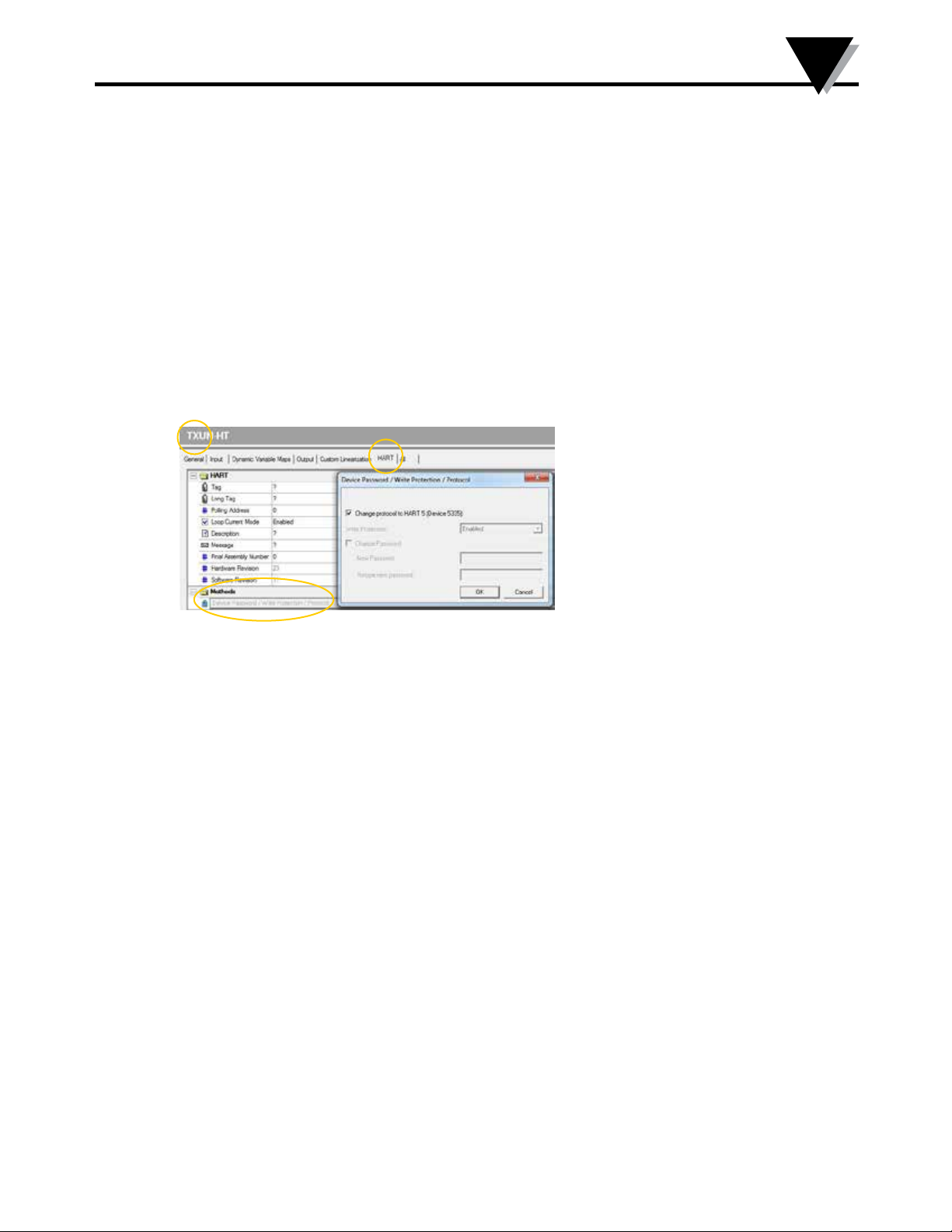
Switching from HART 7 to HART 5
Select the TXUN-HT product, click the "HART" tab and open the folder ”Methods”.
Click ”Device Password / Write Protection / Protocol...” and select ”Change protocol to HART 5” in the popup window, then acknowledge by pressing OK.
12
Page 13
6
Changing the Hart protocol Version
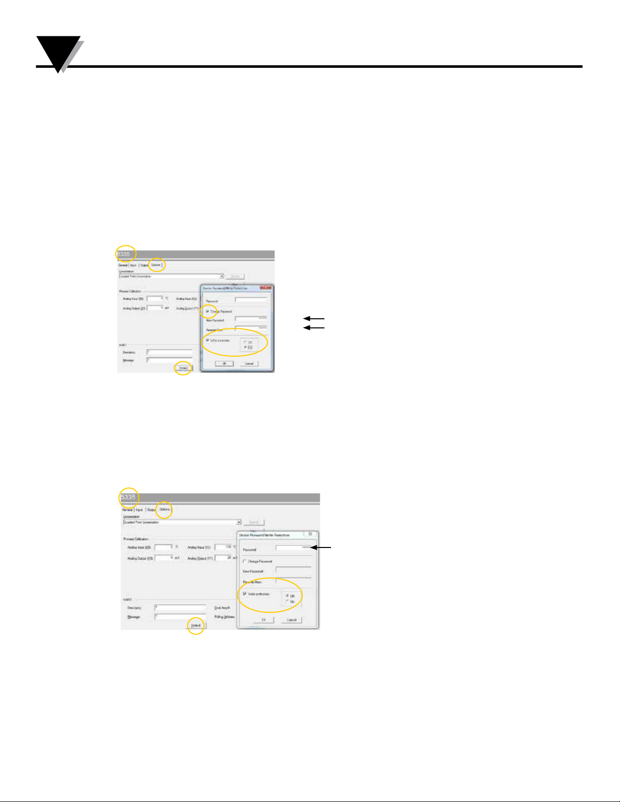
Switching from HART 5 to HART 7
Please note this is only possible if the transmitter is marked
”TXUN-HT” on the label!
From OMset, select the TXUN-HT product, click the
”OPTIONS” tab click ”Protect”.
Write protection must be set to ”ON”. Select Change Password.
Type in the New Password ”HARTREV7” and Re-enter
”HARTREV7”. Click OK.
HARTREV7
Switch Write protection OFF and write-enable the device
by typing in the Password ”-CHANGE-” in the top menu acknowledge by pressing OK.
This action will reset the password to the default active
password " * * * * * * * * " (8 stars) and restart the device in the
updated HART 7 mode with write protection disabled. Now,
select TXUN-HT in OMset and reconfigure the device.
-CHANGE-
13
Page 14
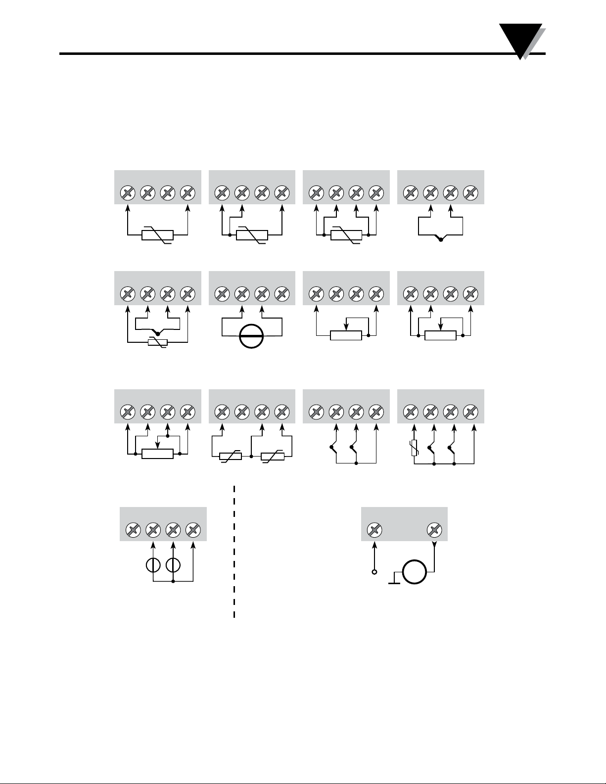
Section 7 - Connections
Input:
Connections
7
RTD, 2-wire RTD, 3-wire RTD, 4-wire
3
4
TC, external CJC mV
3
4
-
Resistance, 4-wire
3
4
+
65 3
65
RTD, dierence
65 3
4
3
4
-
or average
4
65 3
65
+
65
12
4
Resistance, 2-wire Resistance, 3-wire
3
4
TC, dierence
or average,
with internal CJC
3
4
TC, internal CJC
65 3
4
-
65 3
65
+
+
1
2
-
-
4
TC, dierence
or average,
with external CJC
3
4
+
2 1
-
65
+
65
65
+
-
mV, dierence
or average
3
4
+-+
12
-
Output:
65
2-wire installation
1 2
+
mA -
14
Page 15
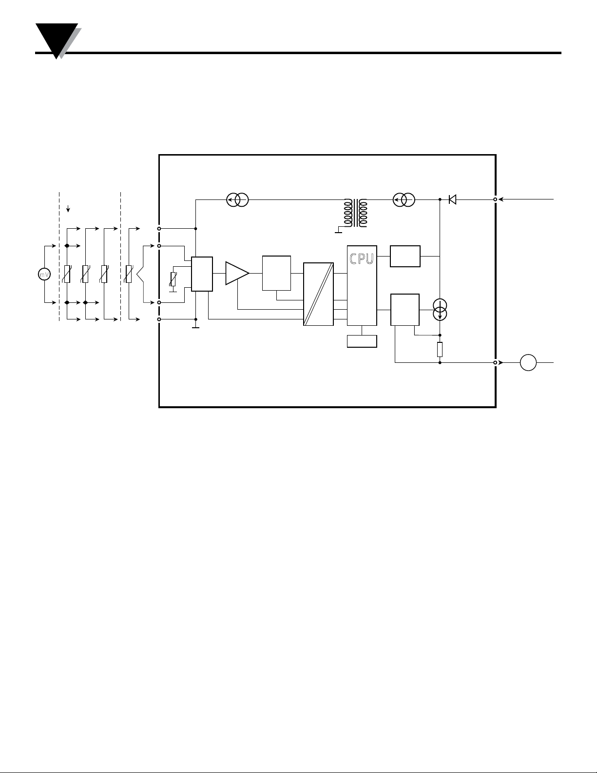
8
Block Diagram
Section 8 - Block Diagram
mV
+
mV
-
RTD, lin. R
- wire
3
4
2
TC
Ext.
CJC
+
-
Input gnd.
6
5
Int.
CJC
M UX
4
3
PGA
A / D
C PU
EE PRO M
4 m A
Comm.
D / A
0.. . 16
mA
8.0...35 VDC
1
2
4...20 mA
Supply +
Supply -
mA
TXUN-HT
15
Page 16
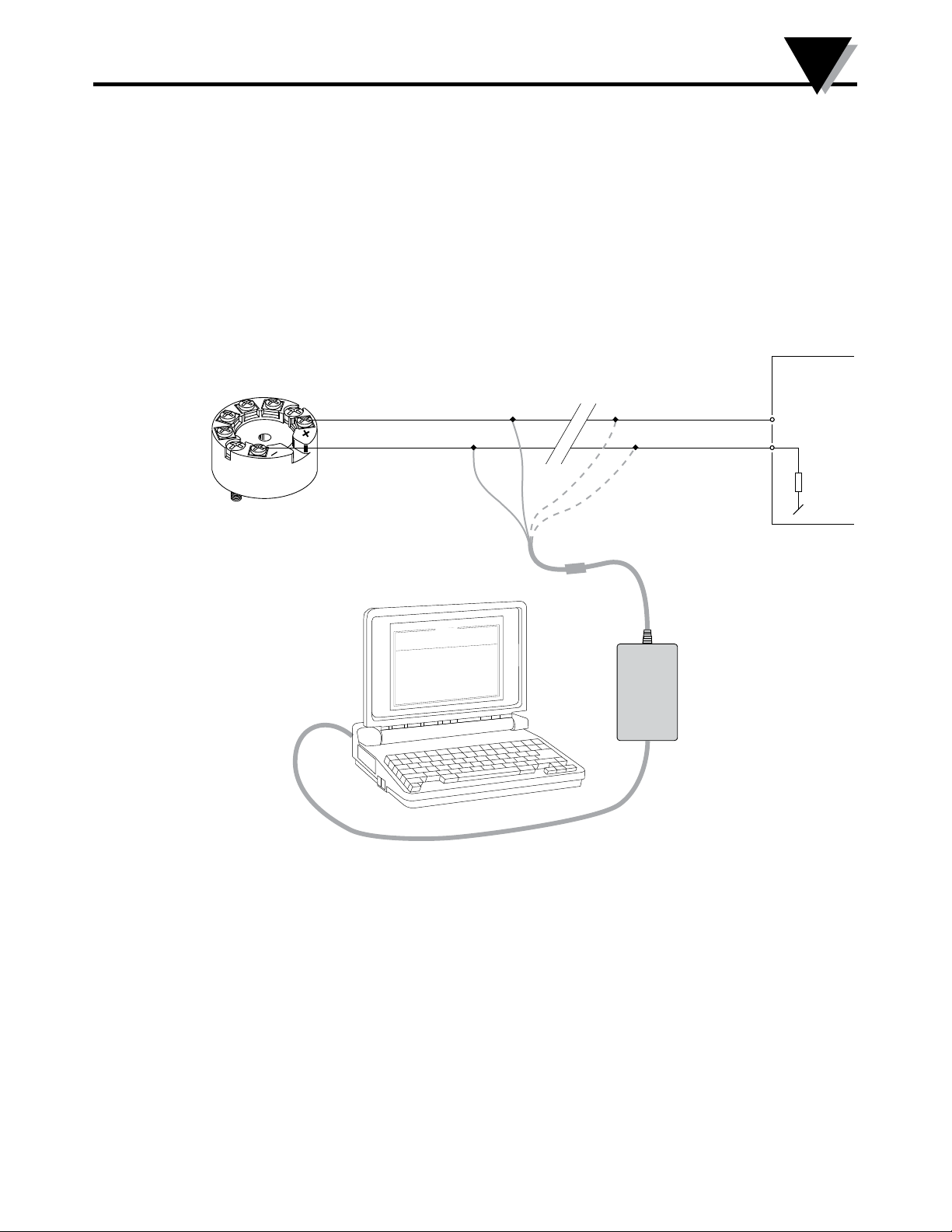
Programming
Section 9 - Programming
TXUN-HT can be configured in the following 3 ways:
1. With Omega TXUN-KIT communications interface Loop Link and OMset PC configuration software.
2. With a HART modem and OMset PC configuration software.
3. With a HART communicator with HART A/S’ DDL driver.
1: Loop Link
For programming please refer to the drawing below and the help functions in OMset.
Loop Link is not approved for communication with devices installed in hazardous (Ex) areas.
Disconnect
1
2
Red
Black
Yellow
*
Green
*
9
Receiving
Equipment
+Vsupply
Input
TXUN-HT
Connector
F
at
D
r
e
S
ag
T
n
A
p
n
I
p
n
I
n
o
C
l
o
C
s
e
R
TXUN-HT
0
1
-
-
8
4
0
0
2
:
e
4
9
5
1
0
2
3
4
0
:
o
n
al
i
Omega Engineering
:
o
n
t
u
p
n
i
g
o
al
:
e
yp
t
t
u
:
e
g
an
r
t
u
:
n
i
o
ct
e
n
p
m
o
c
n
i
o
t
c
n
u
j
d
:
e
i
m
t
se
n
o
p
t
u
p
t
u
o
g
o
al
n
A
A
m
0
2
-
4
:
e
p
y
t
t
u
p
t
u
O
C
E
/
I
I
N
D
0
0
1
t
P
0
5
-
0
0
.
0
e
r
i
w
-
3
-
-
-
-
-
-
:
c
e
s
0
0
.
1
e
al
c
s
p
U
:
r
o
r
r
e
r
o
s
n
e
S
C
0
0
.
Lo o p
Lin k
TXUN-KIT
0
0
:
0
3
:
8
0
n
o
t
i
p
O
e
ag
u
g
n
a
L
n
o
i
at
c
i
n
u
m
m
o
C
t
u
t
p
u
O
t
u
p
n
I
t
c
u
d
o
r
P
l
e
i
* Connected only for
on-line programming
16
Page 17
9
Programming
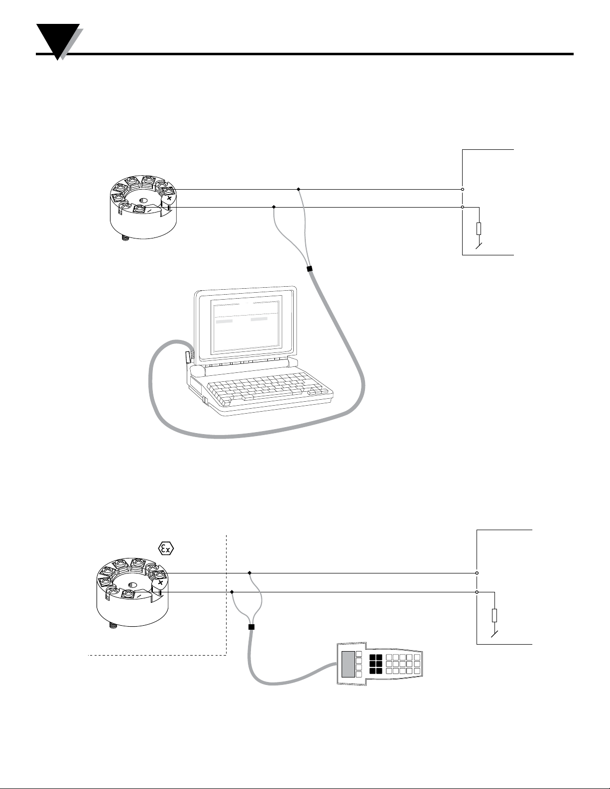
2: HART modem
For programming please refer to the drawing below and the help functions in OMset.
1
2
Rload > 250 W, < 1100 W
TXUN-HT
0
0
:
0
3
:
8
0
n
o
i
t
p
O
e
g
a
u
g
n
a
L
n
o
i
t
a
c
i
n
u
m
m
o
C
t
u
p
t
u
O
t
u
p
n
I
t
c
u
d
o
r
P
HART
®
modem
e
l
i
F
:
e
t
a
D
l
i
a
r
e
S
o
n
g
a
T
a
n
A
t
u
p
n
I
r
t
u
p
n
I
e
n
n
o
C
j
u
l
d
o
C
o
p
s
e
R
1
3
3
5
p
o
t
e
R
P
0
-
1
8
-
4
9
9
1
4
9
5
1
0
2
3
4
9
:
o
n
s
c
i
n
o
r
t
c
e
l
e
R
P
:
t
u
p
i
n
g
l
o
:
e
p
y
t
:
e
g
n
a
:
n
i
o
t
c
:
p
m
o
c
n
o
i
t
c
n
:
e
m
i
t
e
s
n
t
u
p
t
u
o
g
l
o
a
n
A
A
m
0
2
-
4
:
e
p
y
t
t
u
p
t
u
O
C
I
E
/
N
I
D
0
0
1
t
P
0
5
-
0
.
0
0
e
i
r
-
w
3
-
-
-
-
-
c
e
s
0
.
0
1
e
l
a
c
s
p
U
:
r
o
r
r
e
r
o
s
n
e
S
C
0
.
0
Receiving
Equipment
+Vsupply
Input
3: HART communicator
For programming please refer to the drawing below. To gain access to product-specific commands, a
suitable HART communicator must be loaded with the HART A/S DDL driver. This can be ordered at
the HART Communica tion Foundation.
area
1
2
Safe area
Rload
> 250 W, < 1100 W
Receiving
Equipment
+Vsupply
Input
TXUN-HT
17
Page 18
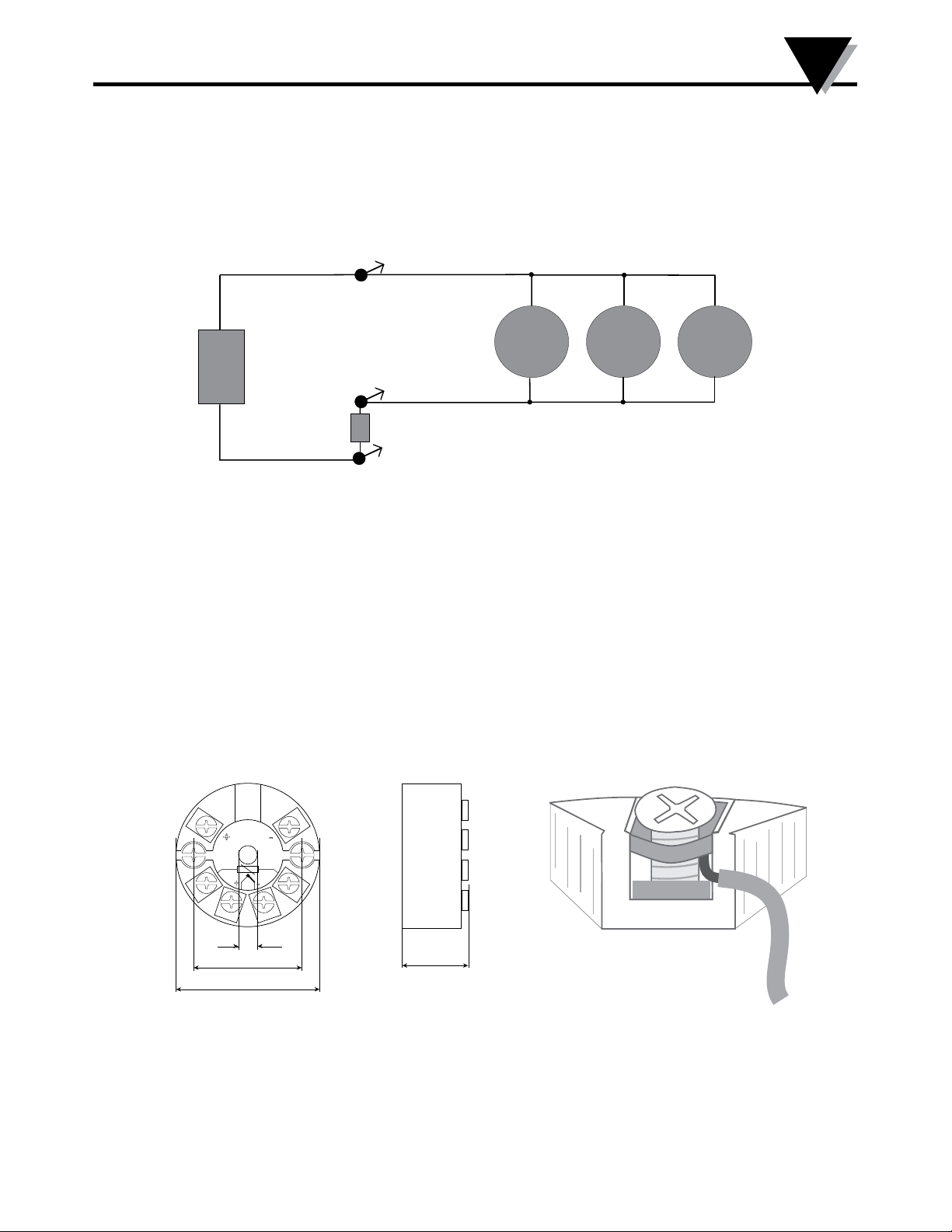
Connection of Transmitters in Multidrop Mode
A
-
+
Section 10 - Connection of Transmitters in Multidrop Mode
The HART communicator or a PC modem can be connected accross AB or BC.
+
10
Power
supply
TXUN-HT
B
-
Rload
> 250 W, < 1100 W
R
TXUN-HT
Max. 63 transmitters
TXUN-HT
C
The outputs of max. 63 transmitters can be connected in parallel for a digital HART 7
communication on 2-wires.
Before it is connected, each transmitter must be configured with a unique number from 1
to 63. If 2 transmitters are configured with the same number, both will be excluded. The
transmitters must be programmed for multidrop mode (with a fixed output signal of 4 mA).
Maximum current in the loop is therefore 252 mA.
The communication is either by means of a HART communicator or a HART modem.
The OMset PC configuration software can configure the individual transmitter for multidrop
mode and provide it with a unique polling address.
Mounting of sensor wires
Section 10.2 - Mechanical specifications
-
+
+
-
ø 6 mm
33 mm
ø 44 mm
20.2 mm
Section 10.3 - Mounting of sensor wires
Wires must be mounted
between the metal plates.
18
Page 19

11
Appendix
Appendix
ATEX Installation Drawing - TXUN-HT - pg20
IECEx installation drawing - TXUN-HT - pg21
FM Installation Drawing - TXUN-HT - pg 26
CSA Installation Drawing - TXUN-HT - pg 28
19
Page 20
5335QE01
LERBAKKEN 10, 8410 RØNDE DENMARK. WWW.PRELECTRONICS.COM
5335QE01
LERBAKKEN 10, 8410 RØNDE DENMARK. WWW.PRELECTRONICS.COM
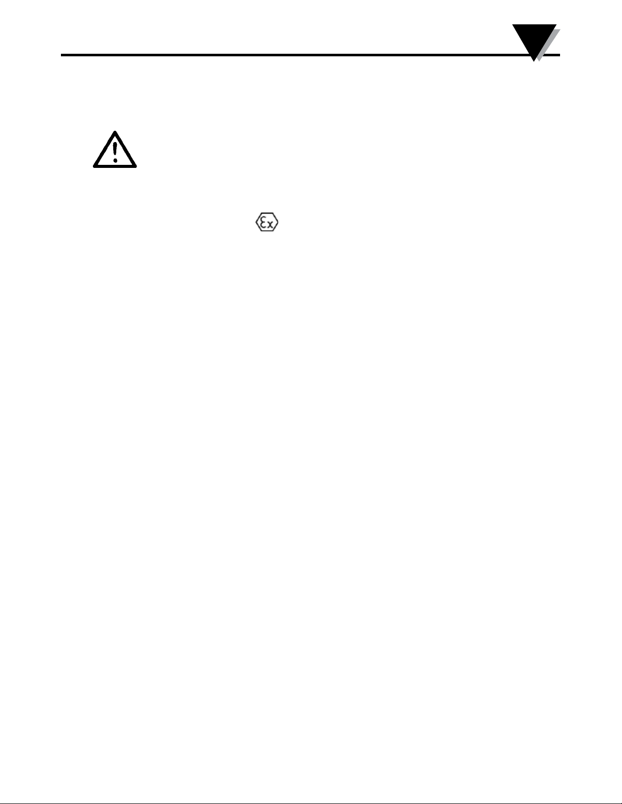
ATEX Installation drawing TXUN-HT
For safe installation of TXUN-HT the following must be observed. The module shall only
be installed by qualified personnel who are familiar with the national and international laws,
directives and standards that apply to this area.
Year of manufacture can be taken from the first two digits in the serial number.
ATEX Certificate KEMA 03ATEX 1508X
Standards EN 60079-0:2012, EN 60079-11:2012, EN 60079-15:2010
General installation instructions
For installation in a potentialy explosive gas atmosphere, the following instructions apply:
For installation in a potentially explosive dust atmposphere, the following instructions apply:
Marking
T4: -40 ≤ Ta ≤ 85ºC
T6: -40 ≤ Ta ≤ 60ºC
If the enclosure is made of non-metallic materials or of painted metal, electrostatic charging
shall be avoided.
For an ambient temperature ≥ 60ºC, heat resistant cables shall be used with a rating of at
least 20 K above the ambient temperature.
For “Ex ic” the transmitter must be installed in an enclosure providing a degree of protection of
at least IP20 according to EN60529 that is suitable for the app
installed.
For “Ex nA” the transmitter must be installed in an enclosure providing a degree of protection
of at least IP54 according to EN60529 that is suitable for the appli
installed, or in an enclosure with type of protection Ex n or Ex e.
Cable entry devices and blanking elements shall fulfill the same requirements.
If the transmitter is supplied with an intrinsically safe signal "ic" and interfaces an intrinsically
safe signal "ic" (e.g. a passive device), the transmitter shall be mounted in a metal enclosure
form B according to DIN 43729 that provides a degree of protection of at least IP6X according
to EN60529, and that is suitable for the application. Cable entry devices and blanking
elements shall fulfill the same requirements.
Terminal: 3,4,5,6
Ex nA [ic]
Uo: 9.6 V
Io: 28 mA
Po: 67 mW
Lo: 45 mH
Co: 28 μF
II 3 G Ex nA [ic] IIC T6..T4 Gc
II 3 G Ex ic IIC T6..T4 Gc
II 3 D Ex ic IIIC Dc
Terminal: 1,2
Ex nA
U ≤ 35 VDC
I = 4 - 20 mA
lication and is correctly
cation and is correctly
Appendix
Terminal: 1,2
Ex ic
Ui = 35 VDC
Li = 10 μH
Ci = 1.0 nF
11
If the transmitter is supplied with an non-sparking signal "nA", or interfaces a non
sparking signal, the transmitter shall be mounted in a metal enclosure form B according to
DIN 43729 providing a degree of protection of at least IP6X according to EN60529, and in
conformance with type of protection Ex tD and suitable for the application. Cable entry
devices and blanking elements shall fulfill the same requirements.
20
Page 21

5335QE01
LERBAKKEN 10, 8410 RØNDE DENMARK. WWW.PRELECTRONICS.COM
IECEx Installation drawing TXUN-HT
For safe installation of TXUN-HT the following must be observed. The module shall only be
installed by qualified personnel who are familiar with the national and international laws,
directives and standards that apply to this area.
Year of manufacture can be taken from the first two digits in the serial number.
IECEx Certificate IECEx KEM 10.0083X
Marking
Standards IEC 60079-0 : 2011, IEC 60079-11 : 2011, EN 60079-15 : 2010
T4: -40 ≤ Ta ≤ 85ºC
T6: -40 ≤ Ta ≤ 60ºC
General installation instructions
For installation in a potentialy explosive gas atmosphere, the following instructions apply:
For installation in a potentially explosive dust atmposphere, the following instructions apply:
If the enclosure is made of non-metallic materials or of painted metal, electrostatic charging
shall be avoided.
For an ambient temperature ≥ 60ºC, heat resistant cables shall be used with a rating of at
least 20 K above the ambient temperature.
For “Ex ic” the transmitter must be installed in an enclosure providing a degree of protection of
at least IP20 according to IEC60529 that is suitable for the application and is correctly
installed.
For “Ex nA” the transmitter must be installed in an enclosure providing a degree of protection
of at least IP54 according to IEC60529 that is suitable for the application and is correctly
installed, or in an enclosure with type of protection Ex n or Ex e.
Cable entry devices and blanking elements shall fulfill the same requirements
If the transmitter is supplied with an intrinsically safe signal "ic" and interfaces an intrinsically
safe signal "ic" (e.g. a passive device), the transmitter shall be mounted in a metal enclosure
form B according to DIN 43729 that provides a degree of protection of at least IP6X according
to IEC60529, and that is suitable for the application. Cable entry devices and blanking
elements shall fulfill the same requirements.
If the transmitter is supplied with an non-sparking signal "nA", or interfaces a non
sparking signal, the transmitter shall be mounted in a metal enclosure form B according to
DIN 43729 providing a degree of protection of at least IP6X according to IEC60529, and in
conformance with type of protection Ex tD and suitable for the application. Cable entry
devices and blanking elements shall fulfill the same requirements.
Ex nA [ic] IIC T6..T4 Gc
Ex ic IIC T6..T4 Gc
Ex ic IIIC Dc
Terminal: 3,4,5,6
Ex nA [ic]
Uo: 9.6 V
Io: 28 mA
Po: 67 mW
Lo: 45 mH
Co: 28 μF
Terminal: 1,2
Ex nA
U ≤ 35 VDC
I = 4 - 20 mA
Appendix
Terminal: 1,2
Ex ic
Ui = 35 VDC
Li = 10 μH
Ci = 1.0 nF
11
21
Page 22
11
5335QE01
LERBAKKEN 10, 8410 RØNDE DENMARK. WWW.PRELECTRONICS.COM
Appendix
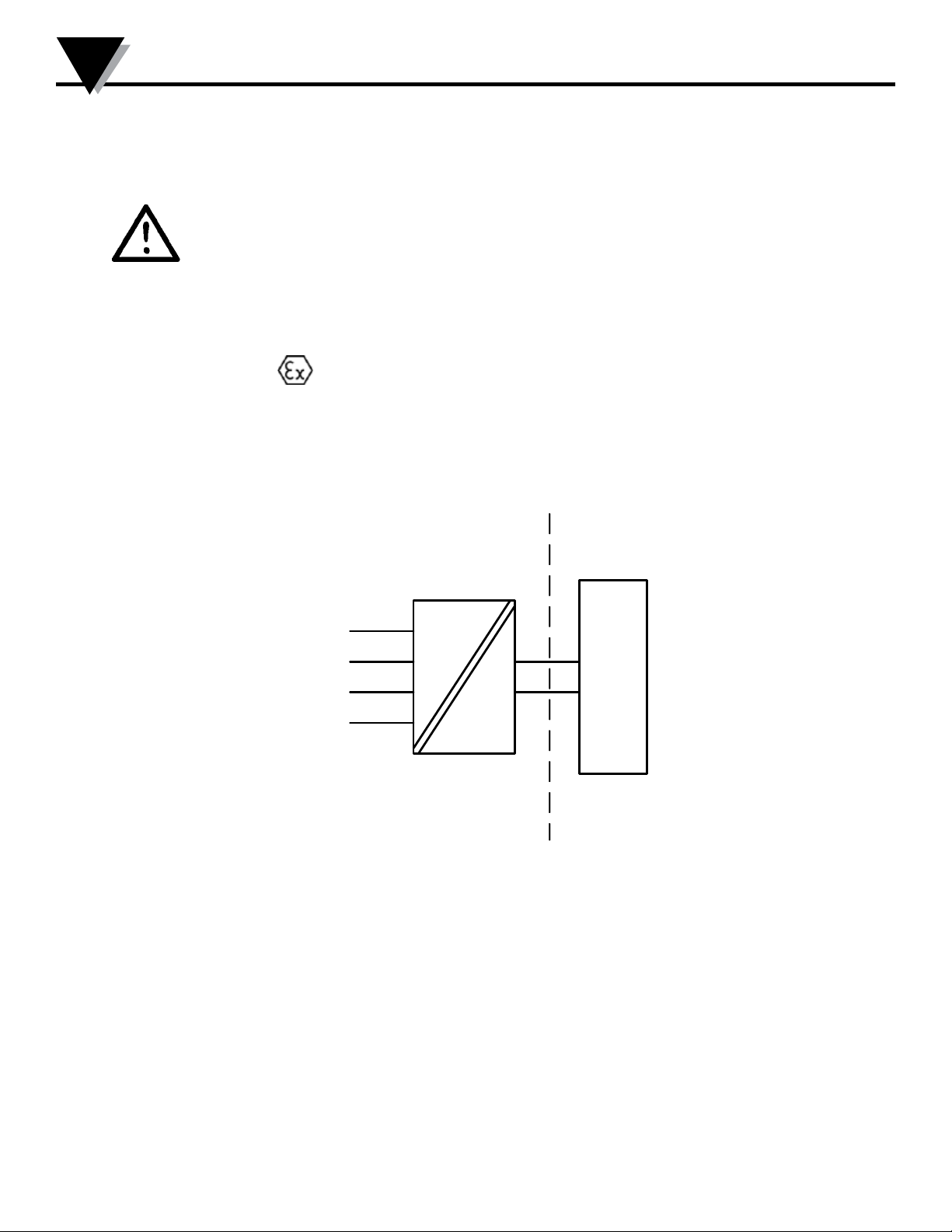
ATEX Installation drawing TXUN-HT
For safe installation of TXUN-HT the following must be observed. The module shall only be
installed by qualified personnel who are familiar with the national and international laws, directives
and standards that apply to this area.
Year of manufacture can be taken from the first two digits in the serial number.
Standards: EN 60079-0 : 2012, EN 60079-11 : 2012, EN 60079-26 : 2007
ATEX Certificate KEMA 03ATEX 1537
Marking
Hazardous area
Zone 0, 1, 2, 20, 21, 22, and Coal mining
T4: -40 ≤ Ta ≤ 85ºC
T6: -40 ≤ Ta ≤ 60ºC
Terminal: 3,4,5,6
Uo: 9.6 VDC
Io: 28 mA
Po: 67 mW
Lo: 35 mH
Co: 3.5 μF
II 1 G Ex ia IIC T6 ...T4 Ga
II 1 D Ex ia IIIC Da
I M1 Ex ia I Ma
6
5
4
3
Terminal: 1,2
Ui: 30 VDC
Ii: 120 mA
Pi: 0.84 W
Li: 10 μH
Ci: 1.0 nF
TXUN-HT
+
1
-
2
Non Hazardous Area
Barrier
22
Page 23

5335QE01
LERBAKKEN 10, 8410 RØNDE DENMARK. WWW.PRELECTRONICS.COM
Installation notes.
General installation instructions
The sensor circuit is not infallibly galvanic isolated from the supply output circuit. However, the
galvanic isolation between the circuits is capable of withstanding a test voltage of 500Vac
during 1 minute.
If the enclosure is made of aluminium, it must be installed such, that even in the event of rare
incidents, ignition sources due to impact and friction, sparks are excluded.
If the enclosure is made of non-metallic materials or painted metals electrostatic charging shall
be avoided.
For installation in a potentially explosive gas atmosphere, the following instructions apply:
The transmitter shall be mounted in an enclosure form B according to DIN43729 or equivalent
that is providing a degree of protection of at least IP20 according to EN60529 that is suitable
for the application and correctly installed.
For installation in a potentially explosive dust atmosphere, the following instructions apply:
The transmitter shall be mounted in a metal enclosure form B according to DIN43729 or
equivalent, that is providing a degree of protection of at least IP6X according to EN60529 that
is suitable for the application and correctly installed.
Cable entries and blanking elements shall be used that are suitable for the application and
correctly installed.
For installalation in mines the following instructions apply:
The transmitter shall be mounted in a metal enclosure that is providing a degree of protection
of at least IP6X according to EN60529, and is suitable for the application and correctly
installed.
Cable entries and blanking elements shall be used that are suitable for the application and
correctly installed
If the enclosure is made of aluminum, it must be installed such, that even in the event of rare
incidents, ignition sources due to impact and friction, sparks are excluded.
If the enclosure is made of non-metallic materials or painted metals electrostatic charging shall
be avoided.
The enclosure shall not contain by mass more than
a) 15 % in total of aluminium, magnesium, titanium and zirconium, and
b) 7,5 % in total of magnesium, titanium and zirconium.
Appendix
11
23
Page 24
11
5331QB01
LERBAKKEN 10, 8410 RØNDE DENMARK. WWW.PRELECTRONICS.COM
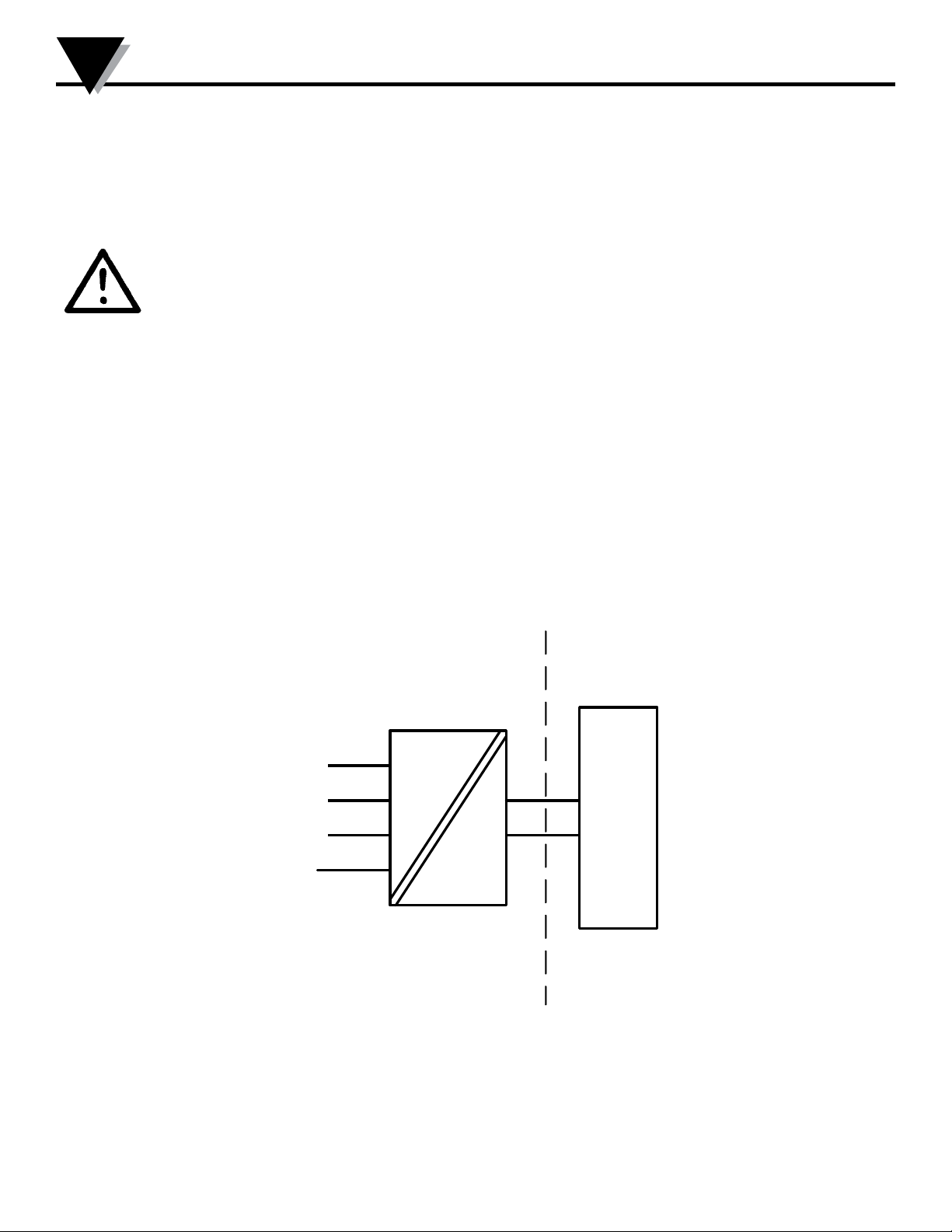
Desenho de Instalação INMETRO
Appendix
Para instalação segura do 5331D ou 5334B o seguinte deve ser observado. O modelo deve apenas
ser instalado por pessoas qualificadas que são familiarizadas com as leis nacionais e
internacionais, diretrizes e padrões que se aplicam a esta área.
O ano de fabricação pode ser pego dos dois primeiros dígitos do número de série.
Certificado …………DEKRA 16.0013 X
Marcas
Normas ABNT NBR IEC 60079-0: 2013; ABNT NBR IEC 60079-11: 2013
Áreas classificadas
Zona 0, 1, 2, 20, 21, 22,
T4: -40 ≤ Ta ≤ 85ºC
T5: -40 ≤ Ta ≤ 60ºC
T6: -40 ≤ Ta ≤ 45ºC
Terminais 3,4,5,6
Uo: 9,6 VDC
Io: 25 mA
Po: 60 mW
Lo: 33 mH
Co: 2,4μF
Ex ia IIC T6…T4 Ga
Ex ia IIIC Da
6
5
4
3
Terminais:
1,2
Ui: 30 VDC
Ii: 120 mA
Pi: 0,84 W
Li: 10μH
Ci: 1,0nF
5331D
5334B
Área não classificada
+
1
-
2
Barrier
24
Page 25

Appendix
5331QB01
LERBAKKEN 10, 8410 RØNDE DENMARK. WWW.PRELECTRONICS.COM
Section 15 - TXUN-HT
Notas de instalação
O circuito do sensor não é isolado galvanicamente do circuito de entrada de forma infalível.
Contudo, a isolação galvânica entre os circuitos é capaz de resistir a um ensaio de tensão de
500Vac durante 1 minuto.
Em uma atmosfera de gás potencialmente explosiva, o transmissor deve ser montado em um
invólucro a fim de garantir um grau de proteção de no mínimo IP20 de acordo com a ABNT
NBR IEC60529. Se contudo, o ambiente necessitar de um nível de proteção maior, isso deve
ser levado em consideração.
Se o transmissor é instalado em uma atmosfera explosiva exigindo o uso de equipamento de
proteção de nível Ga e se o invólucro é feito de alumínio, ele deve ser instalado de modo que,
mesmo em caso remoto de avaria, fontes de ignição devido ao impacto e fricção, faíscas são
eliminadas.
Se o invólucro é feito de materiais não metálicos, cargas eletroestáticas devem ser evitadas.
Para instalação em atmosfera de poeira potencialmente explosiva, as instruções a seguir são
aplicáveis:
O transmissor deve ser montado em invólucro de metal forma B de acordo com DIN43729 que
está fornecendo um grau de proteção de pelo menos IP6X de acordo com ABNT NBR
IEC60529. O invólucro deve ser adequado para aplicação pretendida e instalado
corretamente.
As entradas dos cabos e os elementos de obturação que podem ser utilizados devem ser
adequados à aplicação pretendida e corretamente instalados.
Para temperatura ambiente >= 60ºC, fios de resistência ao calor devem ser usados com uma
faixa de pelo menos 20K acima da temperatura ambiente.
A temperatura da superfície do invólucro é igual à temperatura ambiente mais 20 K, por uma
camada de pó, com espessura de até 5 mm.
11
25
Page 26
5300QF01
LERBAKKEN 10, 8410 RØNDE DENMARK. WWW.PRELECTRONICS.COM
11
Appendix
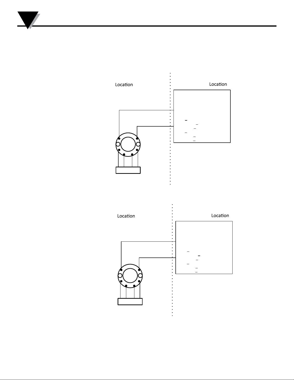
FM Installation Drawing TXUN-FM/TXUN-HT Rev AH
Model TXUN-FM
Hazardous (Classified)
Class I,Division1, Groups, A,B,C,D T4..T6
Class I, Zone 0, AEx ia IIC T4..T6
Ambient temperature limits
T4: -40 to + 85 deg. Celcius
T6: -40 to + 60 deg. Celcius
Terminal 1 , 2
Vmax or Ui: 30 V
Imax or Ii: 120 mA
Pmax or Pi: 0.84 W
Ci: 1 nF
Li:10 uH
Terminal 3,4,5,6
Vt or Uo: 9.6 V
It or Io: 28 mA
Pt or Po: 67.2 mW
Ca or Co: 3.5 uF
La or Lo: 35 mH
1
6
SENSOR
2
3
45
Non Hazardous
Associated Apparatus
+
UM < 250V
Voc or Uo < Vmax or Ui
-
Isc or Io < Imax or Ii
Po < Pi
Ca or Co > Ci + Ccable
La or Lo > Li + Lcable
This device must not be connected
to any associated apparatus which
uses or generates more than 250
VRMS
or Barrier
with
entity Parameters:
Model TXUN-HT
Hazardous (Classified)
Class I,Division1, Groups, A,B,C,D T4..T6
Class I, Zone 0, AEx ia IIC T4..T6
Ambient temperature limits
T4: -40 to + 85 deg. Celcius
T6: -40 to + 60 deg. Celcius
Terminal 1 , 2
Vmax or Ui: 30 V
Imax or Ii: 120 mA
Pmax or Pi: 0.84 W
Ci: 1 nF
Li:10 uH
Terminal 3,4,5,6
Vt or Uo: 9.6 V
It or Io: 28 mA
Pt or Po: 67.2 mW
Ca or Co: 3.5 uF
La or Lo: 35 mH
1
6
SENSOR
2
3
45
Non Hazardous
Associated Apparatus
+
entity Parameters:
UM < 250V
Voc or Uo < Vmax or Ui
-
Isc or Io < Imax or Ii
Po < Pi
Ca or Co > Ci + Ccable
La or Lo > Li + Lcable
This device must not be connected
to any associated apparatus which
uses or generates more than 250
VRMS
or Barrier
with
26
Page 27
5300QF01
LERBAKKEN 10, 8410 RØNDE DENMARK. WWW.PRELECTRONICS.COM
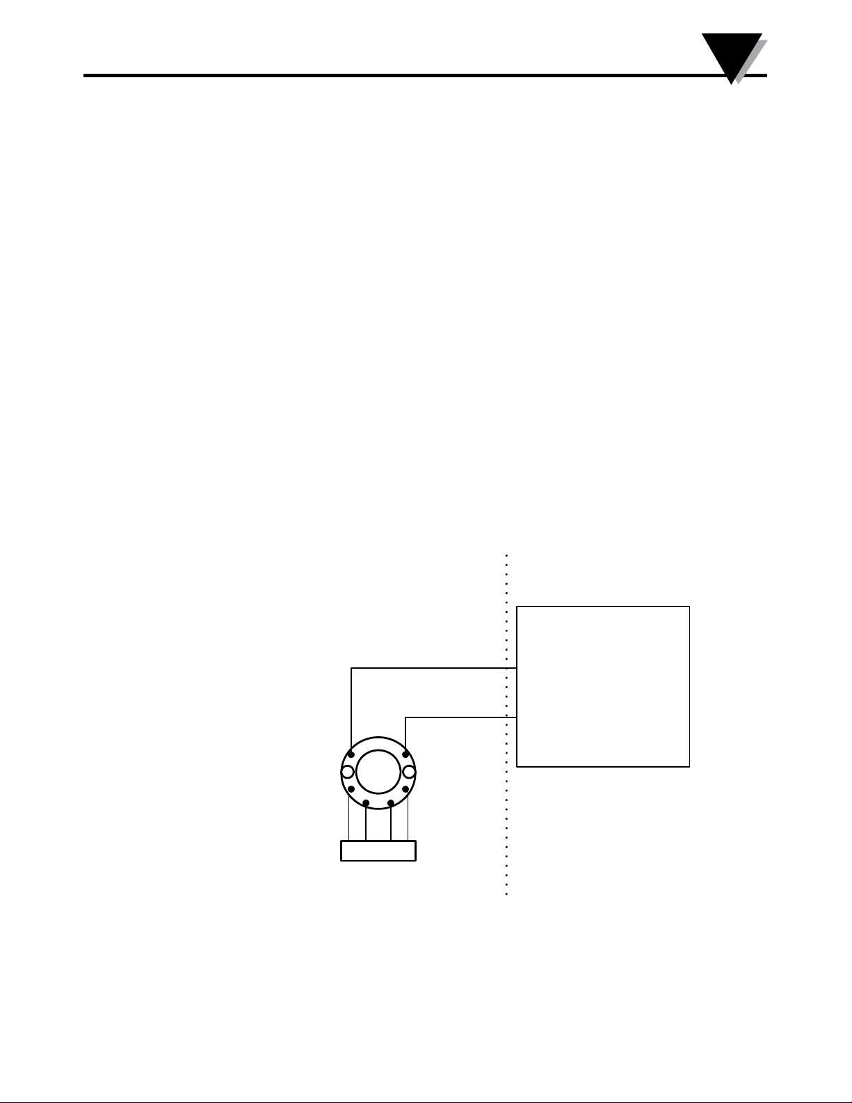
The entity concept
pplication.
s in
rity having
can
ct-
cting
er
The Transmitter must be installed according to National Electrical Code (ANSI-NFPA 70) and shall be
installed with the enclosure, mounting, and spacing segregation requirement of the ultimate a
Equipment that is FM-approved for intrinsic safety may be connected to barriers based on the ENTITY
CONCEPT. This concept permits interconnection of approved transmitters, meters and other device
combinations which have not been specifically examined by FM, provided that the agency's criteria are
met. The combination is then intrinsically safe, if the entity concept is acceptable to the autho
jurisdiction over the installation.
The entity concept criteria are as follows:
he intrinsically safe devices, other than barriers, must not be a source of power.
The maximum voltage Ui(V
) and current Ii(I
MAX
), and maximum power Pi(Pmax), which the device
MAX
receive and remain intrinsically safe, must be equal to or greater than the voltage (Uo or V
current (Io or I
The sum of the maximum unprotected capacitance (C
ing wiring must be less than the capacitance (C
The sum of the maximum unprotected inductance (L
wiring must be less than the inductance (L
or It) and the power Po which can be delivered by the barrier.
SC
) for each intrinsically device and the interconne
i
) which can be safely connected to the barrier.
a
) for each intrinsically device and the interconne
i
) which can be safely connected to the barrier.
a
The entity parameters Uo,V
manufacturer.
or Vt and Io,ISC or It, and Ca and La for barriers are provided by the barri
OC
NI Field Circuit Parameters
Model TXUN-FM and TXUN-HT
Hazardous (Classified) Locaon
Class I,Division2, Groups, A,B,C,D T4..T6
Class I, Zone 2, IIC T4..T6
Ambient temperature limits
T4: -40 to + 85 deg. Celcius
T6: -40 to + 60 deg. Celcius
Terminal 1 , 2
Vmax : 35 V
Ci: 1.0 nF
Li:10 uH
1
2
Non Hazardous Locaon
Associated Apparatus
+
-
6
SENSOR
3
45
This device must not be connected
to any associated apparatus which
uses or generates more than 250
VRMS
or Barrier
Appendix
or Vt) and
OC
11
27
Page 28
5335QE01
LERBAKKEN 10, 8410 RØNDE DENMARK. WWW.PRELECTRONICS.COM
11
Appendix
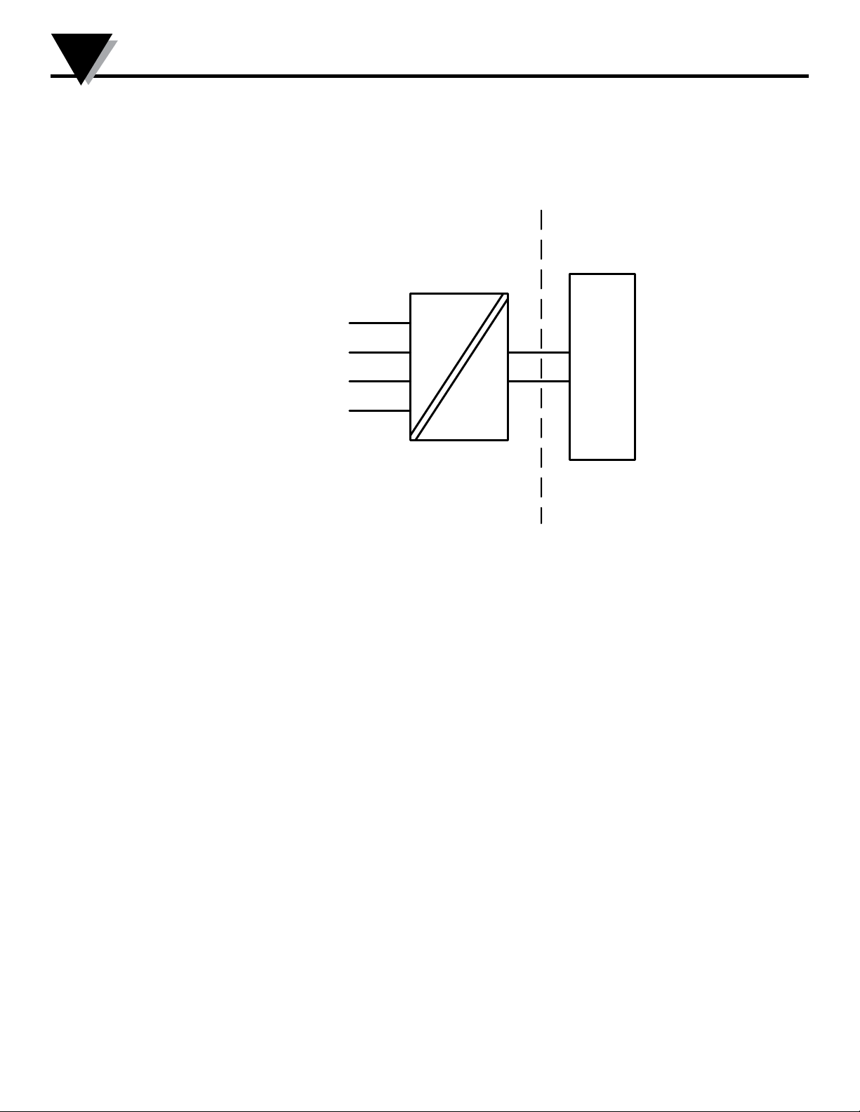
CSA Installation drawing TXUN-FM/TXUN-HT
Hazardous area
T4: -40 ≤ Ta ≤ 85ºC
T6: -40 ≤ Ta ≤ 60ºC
Module TXUN-FM
Terminal: 3,4,5,6
Only passive, or non-energy
storing devices such as RTD’s
and Thermocouples may be
connected
Module TXUN-HT
Terminal: 3,4,5,6
Uo: 9.6 VDC
Io: 28 mA
Po: 67.2 mW
Lo: 35 mH
Co: 2.5 μF
6
5
4
3
Terminal: 1,2
Ui: 30 VDC
Ii: 120 mA
Pi: 0.84 W
Li: 10 μH
Ci: 1.0 nF
+
1
-
2
CLASS 2258 04 - PROCESS CONTROL EQUIPMENT - Intrinsically Safe Entity - For Hazardous
Locations
Class I, Division 1, Groups A, B, C and D
Ex ia IIC, Ga
CLASS 2258 84 - PROCESS CONTROL EQUIPMENT - Intrinsically Safe Entity - For Hazardous
Locations - Certified to US Standards
Class I, Division 1, Groups A, B, C and D
Class I, Zone 0, AEx ia IIC, Ga
Warning:
Substitution of components may impair intrinsic safety.
The transmitters must be installed in a suitable enclosure to meet installation codes stipulated in
the Canadian Electrical Code (CEC) or for US the National Electrical Code (NEC).
Non Hazardous Area
Barrier
28
Page 29

5335QE01
LERBAKKEN 10, 8410 RØNDE DENMARK. WWW.PRELECTRONICS.COM
Instruções de Segurança TXUN-HT
TXUN-HT: Instalação Ex:
ATENÇÃO - RISCO POTENCIAL DE CARGA ELETROSTÁTICA - VER INSTRUÇÕES
Para a instalação segura do transmissor TXUN-HT em áreas classificadas, deve-se observar o
seguinte:
O módulo necessita ser instalado somente por pessoal qualificado e que tenham familiaridade com
normas internacionais, diretivas e normalização aplicadas à estas áreas.
O ano de fabricação do instrumento pode ser obtido, observando-se os primeiros dois dígitos do seu
número de série.
O circuito do sensor não está com isolação galvânica total em relação ao circuito de entrada. Todavia a
isolação galvânica entre os circuitos é capaz de suportar teste de voltagem de 500 Vac durante 1 minuto.
Appendix
11
O transmissor precisa ser montado em um invólucro com um grau de proteção pelo menos IP-20.
Em atmosferas explosivas compostas por misturas de ar / poeira:
O transmissor somente poderá ser instalado em uma atmosfera potencialmente explosiva composta por
poeira combustível se estiver montado no interior de um invólucro metálico forma B de acordo com a
norma DIN 43729 com um grau de proteção pelo menos IP-6X de acordo com a norma IEC 60529, que
seja adequado para esta aplicação e corretamente instalado.
As entradas dos cabos e outras barreiras a
instaladas.
Onde a temperatura ambiente for ≥60ºC, devem ser utilizados cabos resistentes ao calor que resistam pelo
menos 20K acima da temperatura ambiente.
Se o invólucro onde o transmissor está montado for feito de alumínio e instalado em Zona 0, 1 ou Zona
20,21 ou 22, este não deve conter mais do que 6% do seu peso total de magnésio e titânio.
Acessórios adicionais ao invólucro devem ser projetados e/ou instalados de tal modo que até mesmo
eventos de rara incidência , fontes de ignição causadas por impactos e faíscas por fricção sejam
excluídas.
se
rem utilizadas devem ser adequadas e corretamente
29
Page 30

5335QE01
LERBAKKEN 10, 8410 RØNDE DENMARK. WWW.PRELECTRONICS.COM
11
Appendix
Ex ia IIC T6…T4 Ga
Ex ia I Ma
Certificado:: NCC 12.0844 X
Temp. amb. máxima T1...T4 ............... 85°C
Temp. amb. máxima T5 e T6 .............. 45°C
Aplicável em Zona ............................... 0, 1, 2
Sinal de saída / alimentação , terminal 1 e 2:
Ui .......................................................... : 30 VDC
Ii ........................................................... : 120 mADC
Pi .......................................................... : 0,84 W
Li .......................................................... : 10 µH
Ci .......................................................... : 1,0 nF
Entrada do sensor, terminais 3, 4, 5 e 6:
Uo ........................................................ : 9,6 VDC
Io .......................................................... : 28 mA
Po ......................................................... : 67 mW
Lo ......................................................... : 35 mH
Co ........................................................ : 3,5 µF
TXUN-HT: Instalação Ex:
ATENÇÃO - RISCO POTENCIAL DE CARGA ELETROSTÁTICA - VER INSTRUÇÕES
Montado no interior de um invólucro metálico forma B de acordo com a norma DIN 43729 com um grau de
proteção pelo menos IP-54 de acordo com a norma IEC 60529, que seja adequado para esta aplicação e
corretamente instalado.
Ex nA [ic] IIC T6...T4 Gc
Ex ic IIC T6...T4 Gc
Certificado:: NCC 12.0844 X
Temp. amb. máxima T1...T4 ............... 85°C
Temp. amb. máxima T5 e T6 .............. 60°C
Aplicável em Zona ............................... 2
Sinal de saída / alimentação , terminal 1 e 2:
Ui .......................................................... : 35 VDC
Entrada do sensor, terminais 3, 4, 5 e 6
Uo ........................................................ : 9,6 VDC
Io .......................................................... : 28 mA
Po ......................................................... : 67 mW
Lo ......................................................... : 35 mH
Co ........................................................ : 3,5 µF
:
30
Page 31

WARRANTY/DISCLAIMER
OMEGA ENGINEERING, INC. warrants this unit to be free of defects in materials and workmanship for a
period of 13 months from date of purchase. OMEGA’s WARRANTY adds an additional one (1) month grace
period to the normal one (1) year product warranty to cover handling and shipping time. This ensures
that OMEGA’s customers receive maximum coverage on each product.
If the unit malfunctions, it must be returned to the factory for evaluation. OMEGA’s Customer Service
Department will issue an Authorized Return (AR) number immediately upon phone or written request.
Upon examination by OMEGA, if the unit is found to be defective, it will be repaired or replaced at no
charge. OMEGA’s WARRANTY does not apply to defects resulting from any action of the purchaser,
including but not limited to mishandling, improper interfacing, operation outside of design limits,
improper repair, or unauthorized modification. This WARRANTY is VOID if the unit shows evidence of
having been tampered with or shows evidence of having been damaged as a result of excessive corrosion;
or current, heat, moisture or vibration; improper specification; misapplication; misuse or other operating
conditions outside of OMEGA’s control. Components in which wear is not warranted, include but are not
limited to contact points, fuses, and triacs.
OMEGA is pleased to offer suggestions on the use of its various products. However,
OMEGA neither assumes responsibility for any omissions or errors nor assumes liability for
any damages that result from the use of its products in accordance with information provided
by OMEGA, either verbal or written. OMEGA warrants only that the parts manufactured by the
company will be as specified and free of defects. OMEGA MAKES NO OTHER WARRANTIES OR
REPRESENTATIONS OF ANY KIND WHATSOEVER, EXPRESSED OR IMPLIED, EXCEPT THAT OF
TITLE, AND ALL IMPLIED WARRANTIES INCLUDING ANY WARRANTY OF MERCHANTABILITY
AND FITNESS FOR A PARTICULAR PURPOSE ARE HEREBY DISCLAIMED. LIMITATION OF
LIABILITY: The remedies of purchaser set forth herein are exclusive, and the total liability of
OMEGA with respect to this order, whether based on contract, warranty, negligence,
indemnification, strict liability or otherwise, shall not exceed the purchase price of the
component upon which liability is based. In no event shall OMEGA be liable for
consequential, incidental or special damages.
CONDITIONS: Equipment sold by OMEGA is not intended to be used, nor shall it be used: (1) as a “Basic
Component” under 10 CFR 21 (NRC), used in or with any nuclear installation or activity; or (2) in medical
applications or used on humans. Should any Product(s) be used in or with any nuclear installation or
activity, medical application, used on humans, or misused in any way, OMEGA assumes no responsibility
as set forth in our basic WARRANTY/DISCLAIMER language, and, additionally, purchaser will indemnify
OMEGA and hold OMEGA harmless from any liability or damage whatsoever arising out of the use of the
Product(s) in such a manner.
RETURN REQUESTS/INQUIRIES
Direct all warranty and repair requests/inquiries to the OMEGA Customer Service Department. BEFORE
RETURNING ANY PRODUCT(S) TO OMEGA, PURCHASER MUST OBTAIN AN AUTHORIZED RETURN (AR)
NUMBER FROM OMEGA’S CUSTOMER SERVICE DEPARTMENT (IN ORDER TO AVOID PROCESSING
DELAYS). The assigned AR number should then be marked on the outside of the return package and on any
correspondence.
The purchaser is responsible for shipping charges, freight, insurance and proper packaging to prevent
breakage in transit.
FOR WARRANTY RETURNS, please have the
following information available BEFORE contacting
OMEGA:
1. Purchase Order number under which the product
was PURCHASED,
2. Model and serial number of the product under
warranty, and
3. Repair instructions and/or specific problems
relative to the product.
OMEGA’s policy is to make running changes, not model changes, whenever an improvement is possible. This affords our
customers the latest in technology and engineering.
OMEGA is a trademark of OMEGA ENGINEERING, INC.
© Copyright 2018 OMEGA ENGINEERING, INC. All rights reserved. This document may not be copied, photocopied,
reproduced, translated, or reduced to any electronic medium or machine-readable form, in whole or in part, without the prior
written consent of OMEGA ENGINEERING, INC.
FOR NON-WARRANTY REPAIRS, consult
OMEGA for current repair charges. Have
the following information available BEFORE
contacting OMEGA:
1. Purchase Order number to cover the COST
of the repair,
2. Model and serial number of the product, and
3. Repair instructions and/or specific problems
relative to the product.
Page 32

Where Do I Find Everything I Need for
Process Measurement and Control?
OMEGA…Of Course!
Shop online at omega.com
TEMPERATURE
MU
Thermocouple, RTD & Thermistor Probes, Connectors,
Panels & Assemblies
MU
Wire: Thermocouple, RTD & Thermistor
MU
Calibrators & Ice Point References
MU
Recorders, Controllers & Process Monitors
MU
Infrared Pyrometers
PRESSURE, STRAIN AND FORCE
MU
Transducers & Strain Gages
MU
Load Cells & Pressure Gages
MU
Displacement Transducers
MU
Instrumentation & Accessories
FLOW/LEVEL
MU
Rotameters, Gas Mass Flowmeters & Flow Computers
MU
Air Velocity Indicators
MU
Turbine/Paddlewheel Systems
MU
Totalizers & Batch Controllers
pH/CONDUCTIVITY
MU
pH Electrodes, Testers & Accessories
MU
Benchtop/Laboratory Meters
MU
Controllers, Calibrators, Simulators & Pumps
MU
Industrial pH & Conductivity Equipment
DATA ACQUISITION
MU
Communications-Based Acquisition Systems
MU
Data Logging Systems
MU
Wireless Sensors, Transmitters, & Receivers
MU
Signal Conditioners
MU
Data Acquisition Software
HEATERS
MU
Heating Cable
MU
Cartridge & Strip Heaters
MU
Immersion & Band Heaters
MU
Flexible Heaters
MU
Laboratory Heaters
ENVIRONMENTAL
MONITORING AND CONTROL
MU
Metering & Control Instrumentation
MU
Refractometers
MU
Pumps & Tubing
MU
Air, Soil & Water Monitors
MU
Industrial Water & Wastewater Treatment
MU
pH, Conductivity & Dissolved Oxygen Instruments
M5695/1118
 Loading...