

Page 1
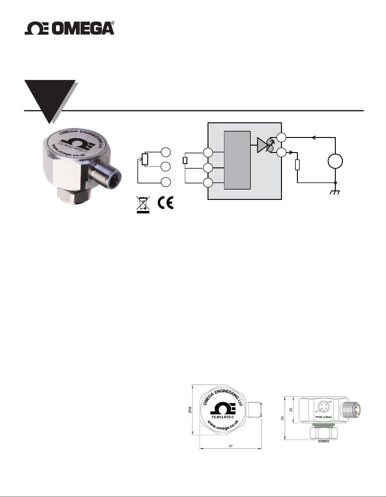
TX-M12-RTD-C
+
-
RTD
Resistance
SUPPLY (Vs) = (10 to 30) V dc
MAX LOAD Ohms = (Vs - 10) / 0.021
Slide Wire
INPUT
OUTPUT
2 Wire (4 to 20) mA
Vs
L
oop
Load
+
-
RTD / Resistance or Slide Wire Input : Two Wire (4 to 20) mA Output
INSTRUCTION
SHEET
MUK002/0611
Shop online at: omega.co.uk e-mail: [email protected]
For latest product manuals: omega.co.uk
1.0 Description
The product is a cost effective "smart" transmitter that accepts resistance signals including RTD sensors and converts them to a standard industrial
(4 to 20) mA transmission signal over a user programmed range.
PC configuration allows the user to select Sensor Type, Range, Units and Error Signal without requiring calibration equipment. Configuration is
performed quickly using our new USB port driven configurator by simply connecting to the units loop and following the software instructions.
Configuration set up may be saved as a file on the PC for later use. Additionally, the user may read live process data when connected to the PC,
allowing for sensor calibration, where the user can enter an offset value to correct any sensor deviation.
2.0 Important safety Information
To maintain CE compliance all input wires must be less than 3 metres.The product contains no user serviceable parts, or internal adjustments.
No attempt should be made to repair this device. Faulty units must be returned to supplier or manufacturer for repair or replacement. This product
must be installed by competent qualified personnel. All electrical wiring must be installed to comply with the area standards, regulations.
Before attempting electrical connection ensure all supplies are switched off.
ABSOLUTE MAXIMUM OPERATING CONDITIONS :-
Supply 30 V dc ( reverse protected to -30 V dc)
Supply Current on over voltage + 100 mA (when supply exceeds 30 V dc protection the device will conduct)
Ambient -40 to + 85 °C
3.0 Mechanical Details
The unit must be installed with adequate protection from
corrosive atmospheres. The correct type of M12 mating
connectors should be used to maintain IP67 protection.
Care must be taken with device location to ensure the
ambient temperature does not exceed the specified
operating temperature.
Every effort has been taken to ensure the accuracy of this document, however we do not accept responsibility for damage, injury, loss or expense
resulting from errors and omissions and we reserve the right of amendment without notice.
Page 2
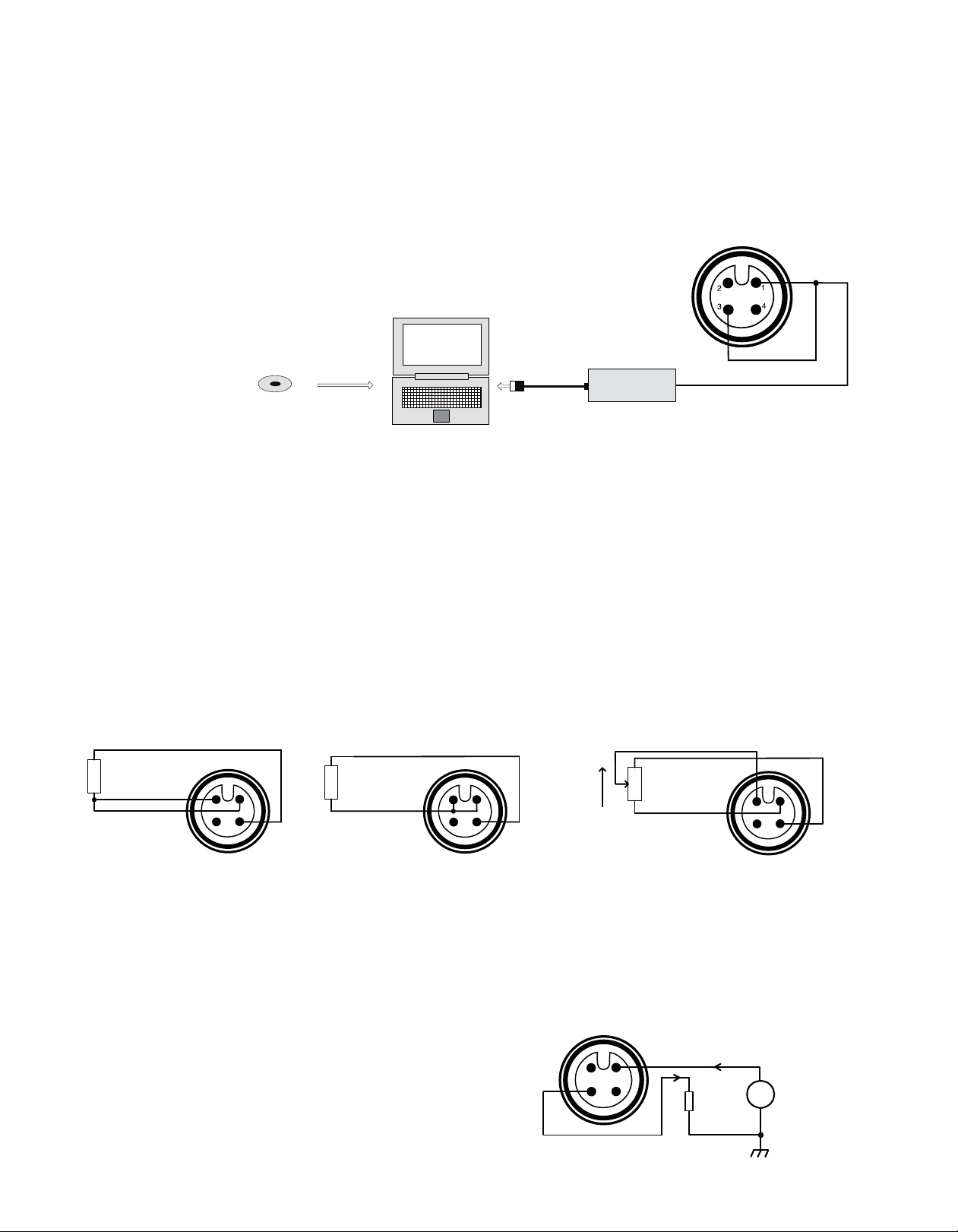
Follow the instructions provided by software menus, refer to the product data sheet for list of configurable parameters.
Factory default PT100 range (0 to 100) °C upscale burnout.
CONFIGURATOR
USB_LINK Software
D
isk or download @
www.omega.co.uk
COMPUTER
USB CONFIGURATOR
1
4
2
3
1
4
2
3
1
4
2
3
OUTPUT
2 Wire (4 to 20) mA
Vs
Loop
Load
+
-
Vs (8 to 30) Vdc
1
4
2
3
+
-
3.0 Installation
or the product specification please refer to product data sheet. Installation is normally performed in the following order. If the product has been
F
purchased as part of a probe assembly steps (1 to 3 ) will have been completed. The user can re-configure the transmitter range on a completed
probe assembly by following from step 1.
For advanced user configuration involving custom sensors and user linearisation contact technical support at the address overleaf.
1. Configuration
2. Probe Assembly
OUTPUT
PLUG
3. Wire Sensor
. Install Assembly
4
5. Wire (4 to 20) mA Loop
1. Configuration
2. Probe assembly
Omega offers two styles of RTD probe assemblies that will connect directly to the sensor input. Please refer to date sheets
for PR-21 and PR-22 probes.
3. Wire sensor
Sensor connections are made by the use of a suitable M12 plug (Omega part No M12-S-M-FM). All sensor connections must be isolated from
ground. To maintain BS EN61326 compliance sensor wires must be less than 3 metres.
Sensor RTD or Resistance (0 to 10.5) Kohm
3 wire
INPUT
SOCKET
2 wire
INPUT
SOCKET
4. Install assembly
Care must be taken as to where the unit is located, so that the ambient temperature of the transmitter does not exceed the specified operating
temperature of (-40 to + 85) °C.
5. Wire (4 to 20) mA Loop
A suitable M12 socket is required for output connection
(Omega part No. M12-R-F-FM). To comply with CE regulations the (4 to 20) mA
loop must be earthed at one point, normally at the power supply. The loop load
symbol represents other equipment in the loop such as an indicator, controller
or signal conditioner.
OUTPUT
PLUG
Slide Wire (0 to 10.5) Kohm
INPUT
SOCKET
Page 3

nline Service Internet e-mail
O
mega.co.uk [email protected]
o
Servicing Europe:
United Kingdom: OMEGA Engineering Ltd.
SO 9001 Certified
I
France: Managed by the United Kingdom Office
One Omega Drive, River Bend Technology Centre, Northbank
Irlam, Manchester M44 5BD United Kingdom
Free Phone: 0800-488-488 TEL: +44 (0) 161 777-6611
FAX: +44 (0) 161 777-6622 e-mail: [email protected]
Toll-Free: 0800 466 342 TEL: +33 (0) 161 37 29 00
FAX: +33 (0) 130 57 54 27 e-mail: [email protected]
U.S.A.: Omega Engineering, Inc., One Omega Drive, P.O. Box 4047
SO 9001 Certified
I
Canada: 976 Bergar
Servicing North America:
Stamford, CT 06907-0047
Toll-Free: 1-800-826-6342 Tel: (203) 359-1660
AX: (203) 359-7700 e-mail: [email protected]
F
Laval (Quebec), H7L 5A1 Canada
Toll-Free: 1-800-826-6342 TEL: (514) 856-6928
FAX: (514) 856-6886 e-mail: [email protected]
Benelux: Managed by the United Kingdom Office
oll-Free: 0800 099 3344 TEL: +31 20 347 21 21
T
FAX: +31 20 643 46 43 e-mail: [email protected]
Germany/Austria: Daimlerstrasse 26, D-75392 Deckenpfronn, Germany
Toll-Free: 0800 6397678 TEL: +49 (0) 7056 9398-0
AX: +49 (0) 7056 9398-29 e-mail: [email protected]
F
It is the policy of OMEGA Engineering, Ltd. to comply with all worldwide safety and EMC/EMI regulations that apply. OMEGA is constantly pursuing certification of its
roducts to the European New Approach Directives. OMEGA will add the CE mark to every appropriate device upon certification.
p
he information contained in this document is believed to be correct, but OMEGA accepts no liability for any errors it contains, and reserves the right to alter specifications without notice.
T
WARNING: These products are not designed for use in, and should not be used for, human applications.
For immediate technical or application assistance:
United Kingdom: Sales Service Free Phone: 0800-488-488 (UK ONLY)
U.S.A. and Canada: Sales Service: 1-800-826-6342/1-800-TC-OMEGA
Sales Service International: +44(0)-161-777-2225
Engineering Service Direct +44(0) -161-777-2232
®
Customer Service: 1-800-622-2378/1-800-622-BEST
Engineering Service: 1-800-872-9436/1-800-USA-WHEN
®
®
WARRANTY/DISCLAIMER
OMEGA ENGINEERING, LTD. warrants this unit to be free of defects in materials and workmanship for a period of 13 months from date of purchase.
OMEGA’s WARRANTY adds an additional one (1) month grace period to the normal one (1) year product warranty to cover handling and
shipping time. This ensures that OMEGA’s customers receive maximum coverage on each product.
If the unit malfunctions, it must be returned to the factory for evaluation. OMEGA’s Customer Service Department will issue an Authorized Return (AR)
number immediately upon phone or written request. Upon examination by OMEGA, if the unit is found to be defective, it will be repaired or replaced
at no charge. OMEGA’s WARRANTY does not apply to defects resulting from any action of the purchaser, including but not limited to mishandling,
improper interfacing, operation outside of design limits, improper repair, or unauthorized modification. This WARRANTY is VOID if the unit shows
evidence of having been tampered with or shows evidence of having been damaged as a result of excessive corrosion; or current, heat, moisture or
vibration; improper specification; misapplication; misuse or other operating conditions outside of OMEGA’s control. Components in which wear is not
warranted, include but are not limited to contact points, fuses, and triacs.
OMEGA is pleased to offer suggestions on the use of its various products. However, OMEGA neither assumes responsibility for any
omissions or errors nor assumes liability for any damages that result from the use of its products in accordance with information provided
by OMEGA, either verbal or written. OMEGA warrants only that the parts manufactured by the company will be as specified and free of
defects. OMEGA MAKES NO OTHER WARRANTIES OR REPRESENTATIONS OF ANY KIND WHATSOEVER, EXPRESSED OR IMPLIED, EXCEPT
THAT OF TITLE, AND ALL IMPLIED WARRANTIES INCLUDING ANY WARRANTY OF MERCHANTABILITY AND FITNESS FOR A PARTICULAR
PURPOSE ARE HEREBY DISCLAIMED. LIMITATION OF LIABILITY: The remedies of purchaser set forth herein are exclusive, and the total
liability of OMEGA with respect to this order, whether based on contract, warranty, negligence, indemnification, strict liability or otherwise,
shall not exceed the purchase price of the component upon which liability is based. In no event shall OMEGA be liable for consequential,
incidental or special damages.
CONDITIONS: Equipment sold by OMEGA is not intended to be used, nor shall it be used: (1) as a “Basic Component” under 10 CFR 21 (NRC), used in
or with any nuclear installation or activity; or (2) in medical applications or used on humans. Should any Product(s) be used in or with any nuclear
installation or activity, medical application, used on humans, or misused in any way, OMEGA assumes no responsibility as set forth in our basic
WARRANTY / DISCLAIMER language, and, additionally, purchaser will indemnify OMEGA and hold OMEGA harmless from any liability or damage
whatsoever arising out of the use of the Product(s) in such a manner.
Direct all warranty and repair requests/inquiries to the OMEGA Customer Service Department. BEFORE RETURNING ANY PRODUCT(S) TO
RETURN REQUESTS/INQUIRIES
OMEGA, PURCHASER MUST OBTAIN AN AUTHORIZED RETURN (AR) NUMBER FROM OMEGA’S CUSTOMER SERVICE DEPARTMENT (IN ORDER
TO AVOID PROCESSING DELAYS). The ass igned AR number should then be m arked on the outsid e of the return pack age and on any
correspondence.
The purchaser is responsible for shipping charges, freight, insurance and proper packaging to prevent breakage in transit.
FOR WARRANTY
available BEFORE contacting OMEGA:
1. Purchase Order number under which the product was PURCHASED,
2. Model and serial number of the product under warranty, and
3. Repair instructions and/or specific problems relative to the product.
OMEGA’s policy is to make running changes, not model changes, whenever an improvement is possible. This affords our customers the latest in technology and
engineering. OMEGA is a registered trademark of OMEGA ENGINEERING, LTD.
© Copyright 2011 OMEGA ENGINEERING, LTD. All rights reserved. This document may not be copied, photocopied, reproduced, translated, or reduced to any electronic
medium or machine-readable form, in whole or in part, without the prior written consent of OMEGA ENGINEERING, LTD.
RETURNS, please have the following information
FOR NON-WARRANTY REPAIRS,
consult OMEGA for current repair charges.
Have the following information available BEFORE contacting OMEGA:
1. Purchase Order number to cover the COST of the repair,
2. Model and serial number of the product, and
3. Repair instructions and/or specific problems relative to the product.
 Loading...