

Page 1
User’s Guide
Shop online at
omega.com
e-mail: [email protected]
For latest product manuals:
www.omegamanual.info
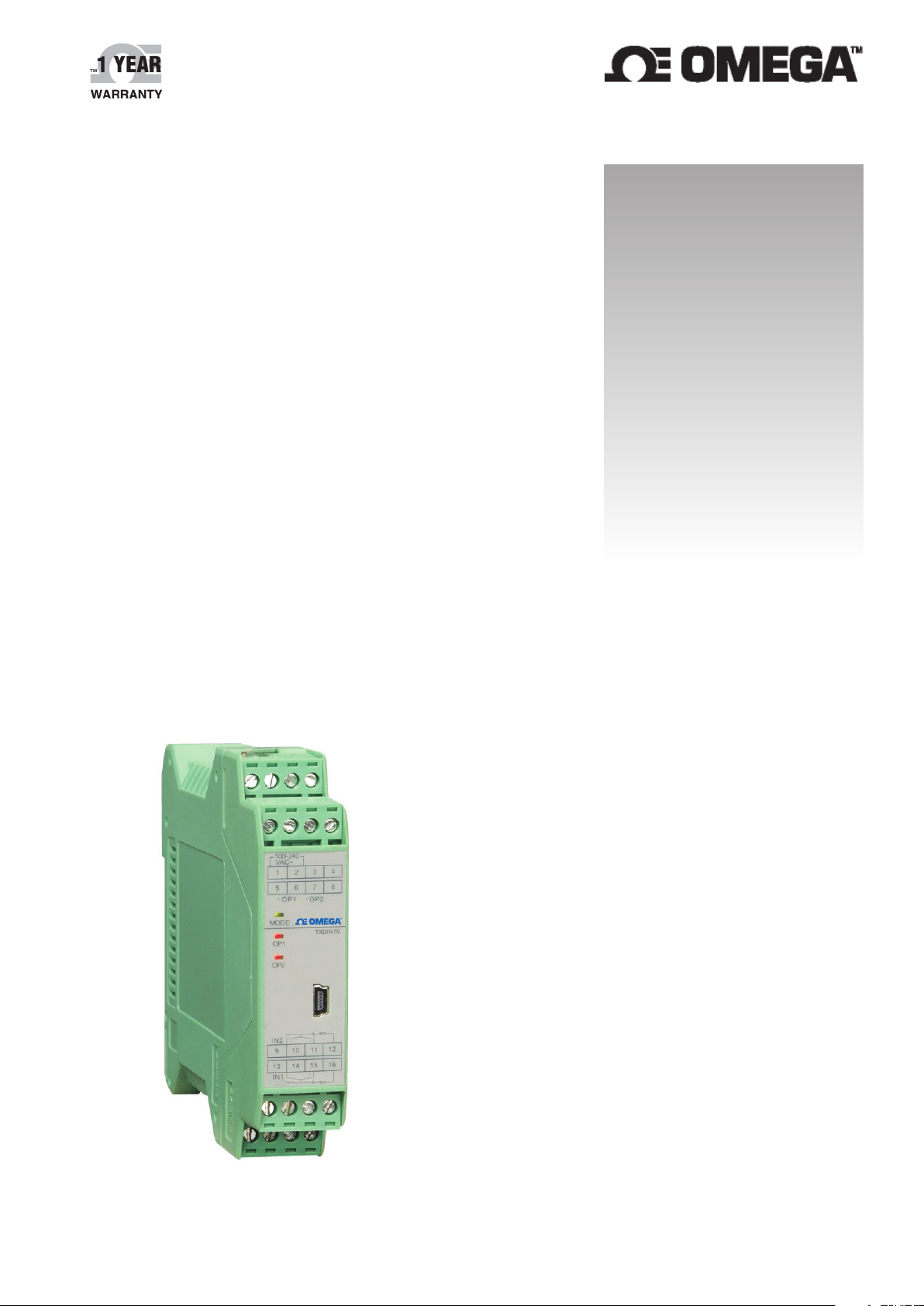
TXDIN70 SERIES
Dual Transmitter
Page 2

omega.com [email protected]
Servicing North America:
U.S.A. Omega Engineering, Inc.
Headquarters: Toll-Free: 1-800-826-6342 (USA & Canada only)
Customer Service: 1-800-622-2378 (USA & Canada only)
Engineering Service: 1-800-872-9436 (USA & Canada only)
Tel: (203) 359-1660 Fax: (203) 359-7700
e-mail: [email protected]
For Other Locations Visit omega.com/worldwide
The information contained in this document is believed to be correct, but OMEGA accepts no liability for any errors it contains, and
reserves the right to alter specifications without notice.
Page 3
MODEL COVERED
TXDIN70
Description: Dual Transmitter
Supply Power: 100~240VAC,50/60Hz
TXDIN70-24V
Description: Dual Transmitter
Supply Power: 24VDC
TXDIN70-DISPLAY
Description: Transmitter Display
Supply Power: From TXDIN70 Transmitter
TECHNICAL SPECIFICATION
Input type: Thermocouple K(-50 °C ~1,300 °C), S(-50 °C ~1,700 °C), R(-50 °C ~1,600 °C),
E(0 °C ~1,000 °C), J(0 °C ~1,200 °C), N(-50 °C ~1,300 °C),
T(-200 °C ~350 °C), B(0 °C ~1,800 °C),
WRe5-WRe26(0 °C ~2,300 °C), WRe3-WRe25(°C 0~ 2,300 °C)
RTD Cu50(-50 °C ~+150 °C), Pt100(-200 °C ~+900 °C)
Linear Voltage 0~1V, 0.2~1V, 0~20mV, 0~60mV, 0~100mV
Retransmission accuracy: 0.3%FS ± 1 digit (including input and output error)
Output specification: Defined in the range of 0~22mA
with maximum output voltage ≥ 11V
Temperature drift: ≤0.015%FS / °C (including the temperature drift of input and output)
Electromagnetic compatibility (EMC):
±4KV/5KHz according to IEC61000-4-4 (EFT);
4KV according to IEC61000-4-5
Isolation withstanding voltage: Voltage between supply power and
signal input output terminals ≥300VDC;
Voltage between inputs or 2 outputs ≥200VDC
Power supply: 100~240VAC, -15%, +10% / 50~60Hz; or 24VDC
Power consumption: ≤ 3W
Operating Ambient : Temperature -10 °C~+60 °C; Humidity ≤90%RH
Remark: Type-B thermocouple operates in the range of 60 °C ~400 °C but the measurement accuracy
does not meet the stated accuracy. Accuracy is guranteed in the range of 400 °C~1,800 °C.
CONNECTION DIAGRAM
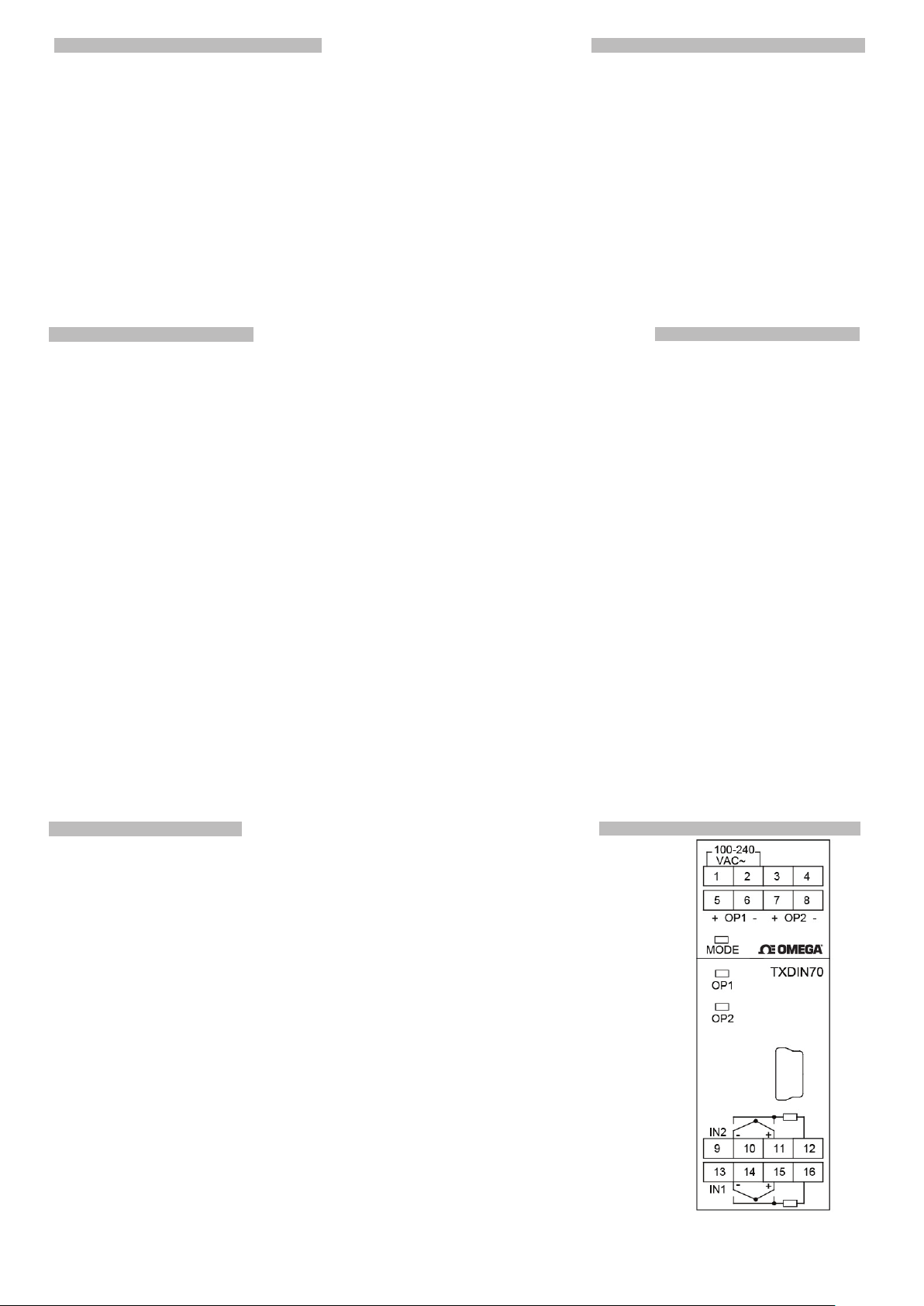
Terminal 1,2: Power supply of 100~240VAC (TXDIN70) or
24VDC (TXDIN70-24V)
Terminal 5,6 OP1: Positive and negative pole of channel 1
current retransmission output.
Terminal 7,8 OP2: Positive and negative pole of channel 2
current retransmission output.
Terminal 14,16 IN1: Channel 1 input.
Terminal 10,12 IN2: Channel 2 input.
OP1 and OP2 lights on when there is outputs in channel 1 and 2. The
luminosity change with the magnitude of output.
MODE light blinks when transmitter is communicatiing with upper device.
Blinking at 1.6 sec cycle: No active communication. Working normal without alarm
Blinking at 0.6 sec cycle: No active communication with alarm
Blinking at 0.3 sec cycle: No active communication with severe fault such as input
out of range.
Light off: No power or out of order.
Light kept on over 8 sec: Transmitter is powered on but it is out of order
Page 4
DISPLAY/OPERATION
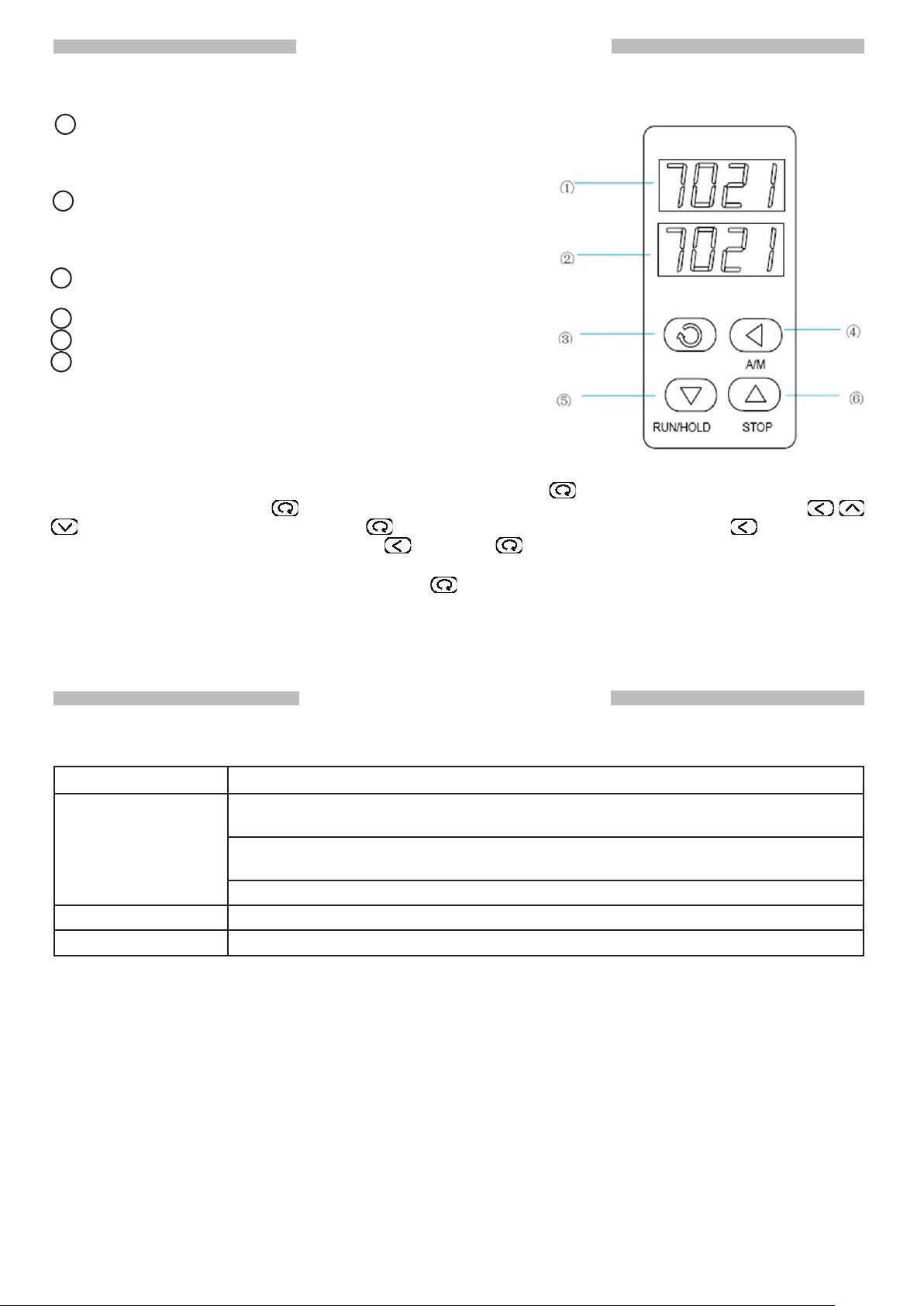
Parameters are set by an hot-plugged display TXDIN70-Display. Apart from nitial set-up, TXDIN70Display can be stay connected serving as an external display.
1 Upper Display: Displays PV of channel 1 or parameter
code, When the display keeps flashing or the reading is
abnormal, please check the input specification whether it is
correctly set.
2 Lower Display : Displays PV of channel 2 or parameter
value. When the display keeps flashing or the reading is
abnormal, please check the input specification whether it is
correctly set.
3 Set Key: Accessing parameter table and to confirm
parameter change.
4 Data Point Shift (to the left)
5 Data Decrease
6 Data Increase
Remark: The bundled IEEE-1394 cable is designed for
communication between TXDIN70-Display and TXDIN70. This
cable is not for other usages.
Entering Parameter Table
When the parameter lock “Loc” is not locked, press and hold for about 2 seconds to bring up the
Full Parameter Table. Press
to modify a parameter value. Press to confirm and proceed to next one. Press and hold will
return to the preceding parameter. Press
parameter table.
When the parameter lock “Loc” is locked, press
parameters INP1,INP2, SCL1, SCL2, SCH1, SCH2. These field parameter value are not allowed to be
changed due to the lock.
The transmitter will automatically escape from the parameter table if there is no keys operation in 25
seconds. The change of the latest parameter will not be saved.
(without holding) to bring up the parameters one by one. Press
and then by holding two keys will escape from the
to bring up Field Parameter Table which show field
TROUBLESHOOTING
When there is a fault, the upper display blinks out an error message.
Error Message Description and Suggestion
orAL Incorrect input specification paramter. Pleaes check the INP1 and/or INP2
parameter.
Thermocouple, RTD or analog input wiring is disconnected. Probe of
thermocouple or RTD is broken. Please check the wiring.
Input wires are short-circuited. Please check the wiring.
EErr IC Software error. Factory repair is required.
8888 IC Software error. Factory repair is required.
Page 5
PARAMETER TABLE
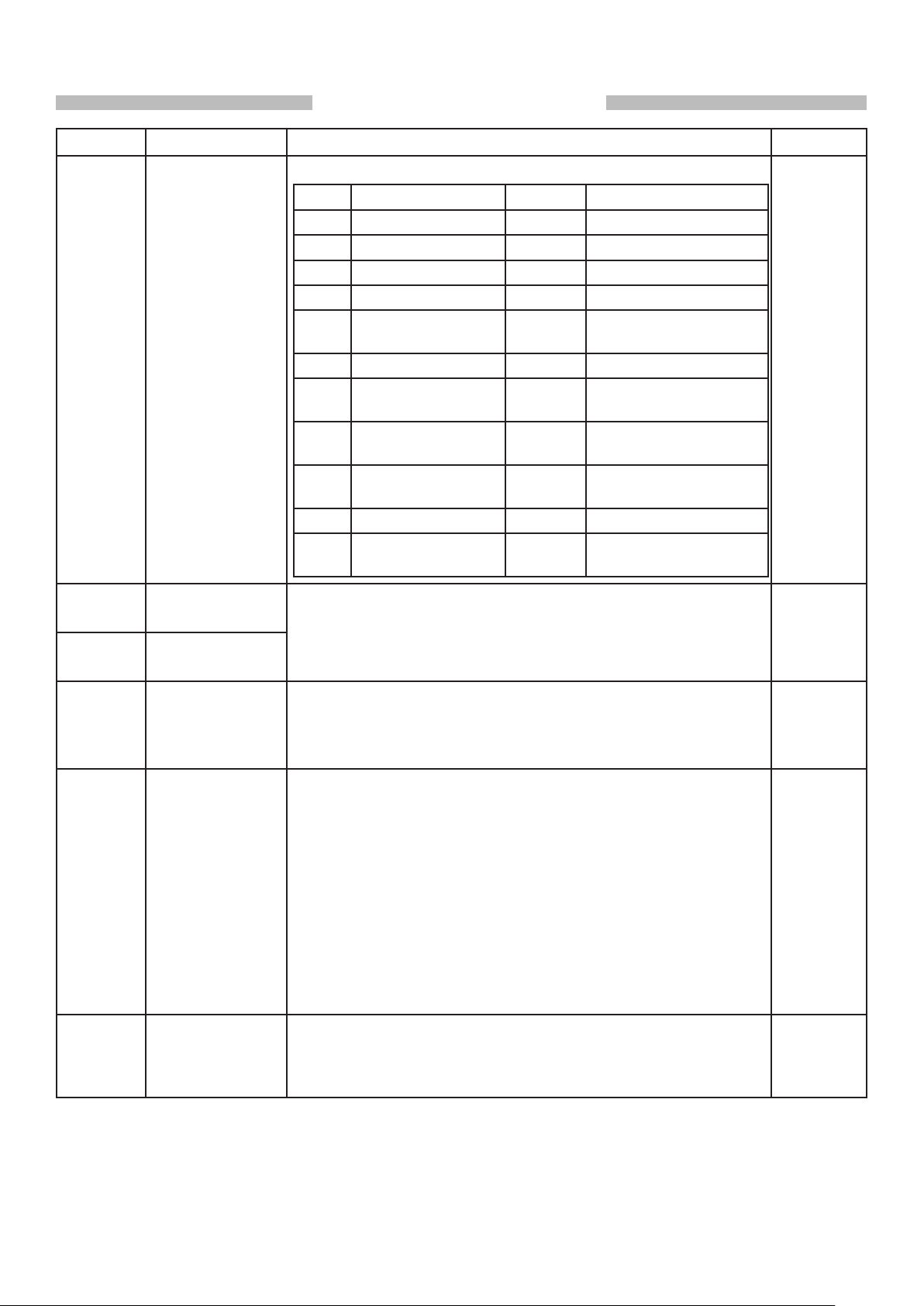
Code Parameter Description Range
INP1/
INP2
Input
Specification
Define the input specification of channel 1~ 2.
InP Input spec. InP Input spec.
0 K 11~19 Spare
1 S 20 Cu50
2 R 21 Pt100
3 T 22~24 Spare
4 E 25 0~75mV voltage
input
5 J 26~27 Spare
6 B 28 0~20mV voltage
input
7 N 29 0~100mV voltage
input
8 WRe3-WRe25 30 0~60mV voltage
input
9 WRe5-WRe26 31 0~1 V
10 Extended input
specification
32 0.2~1V
0~32
SCL1/
SCL2
SCH1/
SCH2
Scb1/
Scb2
FIL1/FIL2 Digital Filter The value of FIL will determine the ability of filtering noise.
OPn Retransmission
Scale Low Limit SCL and SCH define the corresponding scale range of linear
output. For example, for channel 1, in order to retransmit
Scale High Limit
Input Offset Scb is used to shift input to compensate the error caused by
Channel
Assignment
0~600
and SCH1 should be set to 600. For channel 2, to transmit
0~1000
transducer, input signal, or auto cold junction compensation
of thermocouple.
PV_after_compensation=PV_before_compensation + Scb
FIL=0, no filtering;
FIL=1, filtering with mean;
FIL=2~40, filtering with mean and integral.
When a large value is set, the measurement input is
stabilized but the response speed is slow. Generally, it can
be set to 1 to 3.
If great interference exists, then you can increase parameter
FIL gradually to make momentary fluctuation of measured
value less than 2 to 5.
When the instrument is being metrological verified, FIL can
be set to 0 or 1 to shorten the response time.
OPn=1, For 1 input 1 output or 2 inputs 2 outputs
retransmission application,
OPn=2, For 1 input 2 outputs retransmission (Outputs from
input channel 2).
°C to output channel 1, SCL1 should be set to 0,
°C, then SCL2=0, SCH2=1000.
-999~
+3000
units
-199~
+999.0
units/
°C
0.1
0~40
0~2
Page 6

PARAMETER TABLE (cont.)
Code Parameter Description Range
OPL Low Limit
of Current
Retransmission
of Channel 1
OPH High Limit
of Current
Retransmission
of Channel 1
OPL2 Low Limit
of Current
Retransmission
of Channel 2
OPH2 High Limit
of Current
Retransmission
of Channel 2
Define the low limit and high limit of current retransmission
of channel 1. The engineering unit is 0.1mA.
For example, to retransmit 0~600°C in input channel 1
to 4~20mA, then the parameter should be set as below:
SCL1=0, SCH1=600, OPn=1, OPL=40, OPH=200.
Define the low limit and high limit of current
retransmission of channel 2. The engineering unit is
0.1mA.
For example, to retransmit 0~1,000°C in input channel 2
to 4~20mA, then the parameter should be set as below:
SCL1=0, SCH1=1000, OPn=1, OPL=40, OPH=200.
0~110
0~220
0~100
0~220
IVF1 OP1 Current
Correction
(Please record
the value in the
first use)
IVF2 OP2 Current
Correction
(Please record
the value in the
first use)
Loc Parameter Lock Loc=808: Allow to display and modify all parameters.
For adjusting the current of OP1 output. The greater the
value, the greater is the current output.
Note: This parameter is calibrated in factory. It is not
recommended to alter by user.
For adjusting the current of OP2 output. The greater the
value, the greater is the current output.
Note: This parameter is calibrated in factory. It is not
recommended to alter by user.
Loc=any number: All parameters cannot be modified with
only INP1, INP2, SCL1, SCL2, SCH1 and SCH2 showing
0~3000/
Default
( )
0~3000/
Default
( )
0~9999
Page 7

Where Do I Find Everything I Need for
Process Measurement and Control?
OMEGA…Of Course!
Shop online at omega.com
TEMPERATURE
MU
Thermocouple, RTD & Thermistor Probes, Connectors, Panels & Assemblies
MU
Wire: Thermocouple, RTD & Thermistor
MU
Calibrators & Ice Point References
MU
Recorders, Controllers & Process Monitors
MU
Infrared Pyrometers
PRESSURE, STRAIN AND FORCE
MU
Transducers & Strain Gages
MU
Load Cells & Pressure Gages
MU
Displacement Transducers
MU
Instrumentation & Accessories
FLOW/LEVEL
MU
Rotameters, Gas Mass Flowmeters & Flow Computers
MU
Air Velocity Indicators
MU
Turbine/Paddlewheel Systems
MU
Totalizers & Batch Controllers
pH/CONDUCTIVITY
MU
pH Electrodes, Testers & Accessories
MU
Benchtop/Laboratory Meters
MU
Controllers, Calibrators, Simulators & Pumps
MU
Industrial pH & Conductivity Equipment
DATA ACQUISITION
MU Communications-Based Acquisition Systems
MU Data Logging Systems
MU Wireless Sensors, Transmitters, & Receivers
MU Signal Conditioners
MU Data Acquisition Software
HEATERS
MU
Heating Cable
MU
Cartridge & Strip Heaters
MU
Immersion & Band Heaters
MU
Flexible Heaters
MU
Laboratory Heaters
ENVIRONMENTAL
MONITORING AND CONTROL
MU
Metering & Control Instrumentation
MU
Refractometers
MU
Pumps & Tubing
MU
Air, Soil & Water Monitors
MU
Industrial Water & Wastewater Treatment
MU
pH, Conductivity & Dissolved Oxygen Instruments
M4544/0617
Page 8

WARRANTY/DISCLAIMER
OMEGA ENGINEERING, INC. warrants this unit to be free of defects in materials and workmanship
for a period of 13 months from date of purchase. OMEGA’s WARRANTY adds an additional one (1)
month grace period to the normal one (1) year product warranty to cover handling and shipping
time. This ensures that OMEGA’s customers receive maximum coverage on each product.
If the unit malfunctions, it must be returned to the factory for evaluation. OMEGA’s Customer Service
Department will issue an Authorized Return (AR) number immediately upon phone or written request.
Upon examination by OMEGA, if the unit is found to be defective, it will be repaired or replaced at no
charge. OMEGA’s WARRANTY does not apply to defects resulting from any action of the purchaser,
including but not limited to mishandling, improper interfacing, operation outside of design limits,
improper repair, or unauthorized modification. This WARRANTY is VOID if the unit shows evidence of
having been tampered with or shows evidence of having been damaged as a
result of excessive corr
specification; misapplication; misuse or other operating conditions outside of
OMEGA’s control. Components in which wear is not warranted, include but are not
limited to contact points, fuses, and triacs.
OMEGA is pleased to offer suggestions on the use of its various products. However,
O
MEGA neither assumes responsibility for any omissions or errors nor
assumes liability for any damages that result from the use of
in accordance with information provided by OMEGA, either verbal or
written. OMEGA warrants only that the parts manufactured by it will be as
specified and free of defects. OMEGA MAKES NO OTHER WARRANTIES OR
REPRESENTATIONS OF ANY KIND WHATSOEVER, EXPRESS OR IMPLIED, EXCEPT
THAT OF TITLE, AND ALL IMPLIED WARRANTIES INCLUDING ANY WARRANTY OF
MERCHANTABILITY AND FITNESS FOR A PARTICULAR PURPOSE ARE HEREBY
DISCLAIMED. LIMITATION OF LIABILITY: The remedies of purchaser set forth herein are
exclusive, and the total liability of OMEGA with respect to this order, whether
based on contract, warranty, negligence, indemnification, strict liability or otherwise,
shall not exceed the purchase price of the component upon which liability
is based. In no event shall OMEGA be liable for consequential, incidental or special damages.
CONDITIONS: Equipment sold by OMEGA is not intended to be used, nor shall it be used: (1) as a
“Basic Component” under 10 CFR 21 (NRC), used in or with any nuclear installation or activity; or (2)
in medical applications or used on humans. Should any Product(s) be used in or with any nuclear
installation or activity, medical application, used on humans, or misused in any way, OMEGA assumes
no responsibility as set forth in our basic WARRANTY / DISCLAIMER language, and, additionally,
purchaser will indemnify OMEGA and hold OMEGA harmless from any liability or damage whatsoever
arising out of the use of the Product(s) in such a manner.
osion; or current, heat, moisture or vibration; improper
its products
RETURN REQUESTS/INQUIRIES
Direct all warranty and repair requests/inquiries to the OMEGA Customer Service Department.
BEFORE RETURNING ANY PRODUCT(S) TO OMEGA, PURCHASER MUST OBTAIN AN AUTHORIZED
RETURN (AR) NUMBER FROM OMEGA’S CUSTOMER SERVICE DEPARTMENT (IN ORDER TO AVOID
PROCESSING DELAYS). The assigned AR number should then be marked on the outside of the return
package and on any correspondence.
The purchaser is responsible for shipping charges, freight, insurance and proper packaging to prevent
breakage in transit.
FOR WARRANTY RETURNS, please have the
following information available BEFORE
contacting OMEGA:
1.
Purchase Order number under which the
product was PURCHASED,
2.
Model and serial number of the product under
warranty, and
Repair instructions and/or specific problems
3.
relative to the product.
OMEGA’s policy is to make running changes, not model changes, whenever an improvement is possible. This affords
our customers the latest in technology and engineering.
OMEGA is a trademark of OMEGA ENGINEERING, INC.
© Copyright 2018 OMEGA ENGINEERING, INC. All rights reserved. This document may not be copied, photocopied,
reproduced, translated, or reduced to any electronic medium or machine-readable form, in whole or in part, without the
prior written consent of OMEGA ENGINEERING, INC.
FOR NON-WARRANTY REPAIRS,
for current repair charges. Have the following
information available BEFORE contacting OMEGA:
1. Purchase Order number to cover the COST
of the repair,
Model and serial number of the product, and
2.
Repair instructions and/or specific problems
3.
relative to the product.
consult OMEGA
M4544/0618
 Loading...