

Page 1
User’s Guide
Shop online at
omega.com
e-mail: [email protected]
For latest product manuals:
www.omegamanual.info
SM
TXDIN1700
Universal DIN Rail
Page 2

omega.com [email protected]
Servicing North America:
U.S.A. Omega Engineering, Inc.
Headquarters: Toll-Free: 1-800-826-6342 (USA & Canada only)
Customer Service: 1-800-622-2378 (USA & Canada only)
Engineering Service: 1-800-872-9436 (USA & Canada only)
Tel: (203) 359-1660 Fax: (203) 359-7700
e-mail: [email protected]
For Other Locations Visit omega.com/worldwide
The information contained in this document is believed to be correct, but OMEGA accepts no liability for any errors it contains, and reserves
the right to alter specifications without notice.
Page 3
Instruction Manual
Omega TXDIN1700 User Guide V1
1
TXDIN1700 Universal Signal Conditioner
IMPORTANT - CE & SAFETY REQUIREMENTS
This product is suitable for environment Installation category II pollution degree. The product is classed as "PERMANENTLY CONNECTED
EQUIPMENT". Product must be DIN rail mounted, inside a suitable enclosure providing environmental protection to IP65 or greater. Dc supply must be
derived from a local supply and not a distribution system. Max relay contact rating 240 V AC @ 1 A (30 V DC @ 1A). Any circuit connected to a contact
must be fused with a 2 A (T) fuse. To maintain CE EMC requirements , input and supply wires must be less than 30 metres. The product contains no
serviceable parts , or internal adjustments. No attempt must be made to repair this product. Faulty units must be returned to supplier for repair. This
product must be installed by a qualified person. All electrical wiring must be carried out in accordance with the appropriate regulations for the place of
installation. Before attempting any electrical connection work, please ensure all supplies are switched off.
ABSOLUTE MAXIMUM CONDITIONS (To exceed may cause damage to the unit):-
Supply Voltage Ʋ 240 V dc Ʋ 240 V ac (Protected for over voltage)
Input Voltage Ʋ 24 V between any terminals
Input Current Ʋ 50 mA between terminals
Output 30 V dc
Trips (240 V ac @ 1 A, 30 V dc @ 1 A) non inductive
Ambient Temperature (-30 to 75) ƱC
Humidity (10 to 95) % RH (Non condensing)
External Supply 1 Amp anti surge fuse recommended
RECEIVE AND UNPACKING
Please inspect the packaging and instrument thoroughly for any signs of transit damage. If the instrument has been damaged, please notify your
supplier immediately.
CONFIGURATION
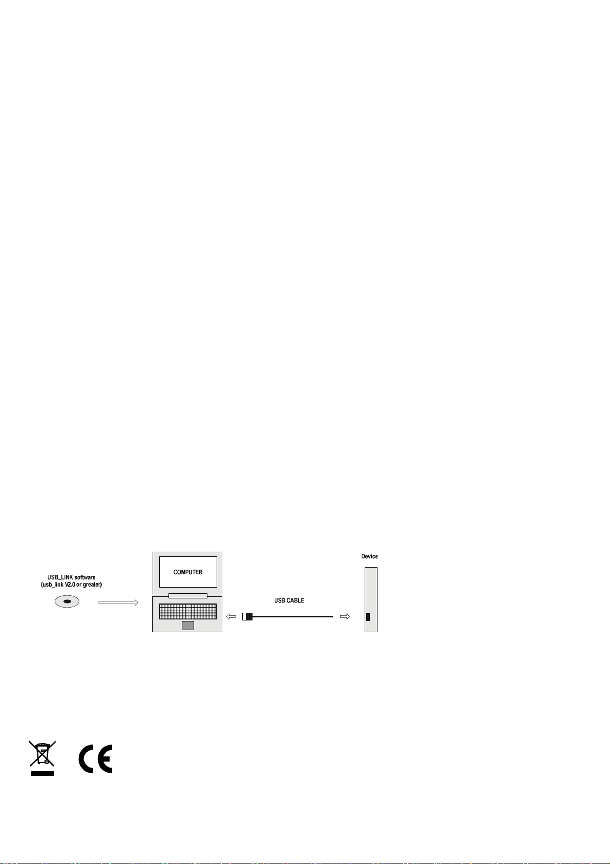
IMPORTANT During configuration the device takes its power from the USB port, therefore no power connection is required. The
device can be configured whilst powered but the computer used must be isolated from the mains supply earth to avoid ground loop effects.
Factory default:
Input type = P
Sample rate = 1000 mS
Units = ƱC
Output = (4 to 20) mA damping 0
High Range = 100
Low Range = 0
Burnout = UPSCALE
User Trim = off
The following parameter can be configured by simply entering as prompted by the software package.
Input type / input sensor / units (temperature inputs) / sample rate
Scale input to process variable (process inputs only)
Analogue Output / Set Type voltage or current / scale output signal range / scale output to process
Set adjustable damping for both rising and falling output. Set correction for voltage output load.
Trip Outputs / Set action / Set setpoints / Set deadband / Set adjustable delay on and delay off
Set burnout direction on sensor failure or input overrange.
Set the function of the front panel user buttons to off, trim or configure. TAG number
Trips = off, delays 0
Damping = 0
Page 4
USER TRIM
Omega TXDIN1700 User Guide V1
2
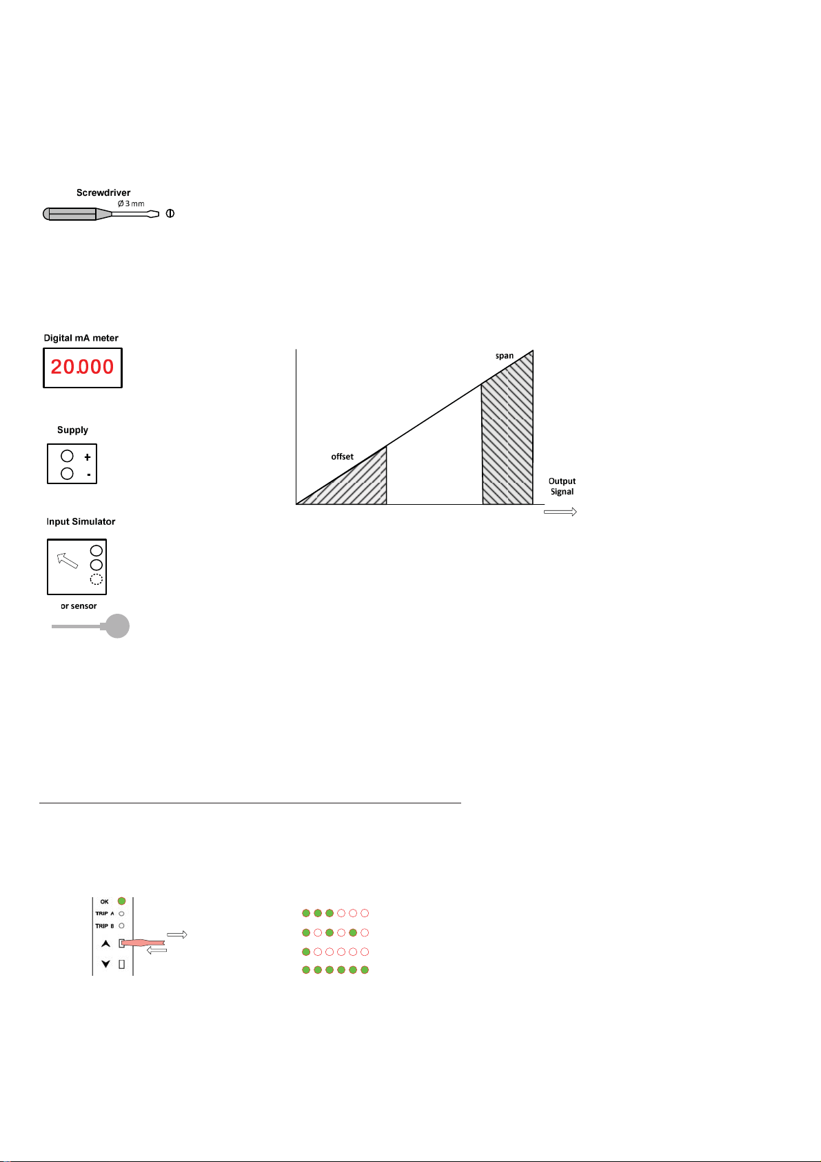
User trim function allows manual adjustment of the analogue output, this is useful for minor calibration adjustment or
trimming out any sensor error, Ʋ 5 % of range adjustment is available at both offset and span. Raise and lower buttons
are provided on the front panel, of the transmitter, accessed using a 3 mm flat blade screw driver. Insert the screw driver
into the appropriate slot to operate the button. The button has a click action.
The transmitter will automatically detect the correct trim point (offset or span) based on the output signal. Offset will be
trimmed when the current is in the offset band, span when the current is in the span band. No trim action occurs at any
other current. Note this function needs to be selected by the software configuration tool before use. To lock setting after
adjustment the operator can again use the tool to turn this function off, (select the option to save trim when downloading
config).
Range Offset
(4 to 20) mA (3.8 to 6) mA (18 to 22) mA
(0 to 20) mA (0 to 2) mA (18 to 22) mA
User mA
User low ƲƲƲƲ 2 mA (Min 0 mA) High ƲƲƲƲ 2 mA (Max 24 mA)
(0 to 10) V (0 to 1) V (9 to 11) V
UserV
User low ƲƲƲƲ 1 V (Min 0 V) User High ƲƲƲƲ 1 V (Max 12 V)
METHOD
1.0 Connect transmitter to a suitable input simulator or sensor. Connect supply,
connecting a digital meter to monitor output. Turn supply on, set input to offset/span
calibration point.
IMPORTANT - IF PERFORMING TWO POINT CAL< ALWAYS CAL OFFSET FIRST.
2.0 Enter trim menu by pressing "raise" button for > two seconds. When the trim
menu is open the range LED will flash :-
ŶƚĞƌ 'ƌĞĞŶKŬ>ǁŝůůŝŶĚŝĐ ĂƚĞdƌŝŵĂĐƚŝŽŶ
KĨĨƐĞƚƐůŽǁƚŽŐŐůĞ
хϮƐ
^ƉĂŶĨĂƐƚƚŽŐŐůĞ
KƵƚŽĨƚƌŝŵƌĂŶŐĞ
/ŶƉƵƚŽƵƚŽĨƌĂŶŐĞ
Span
Page 5
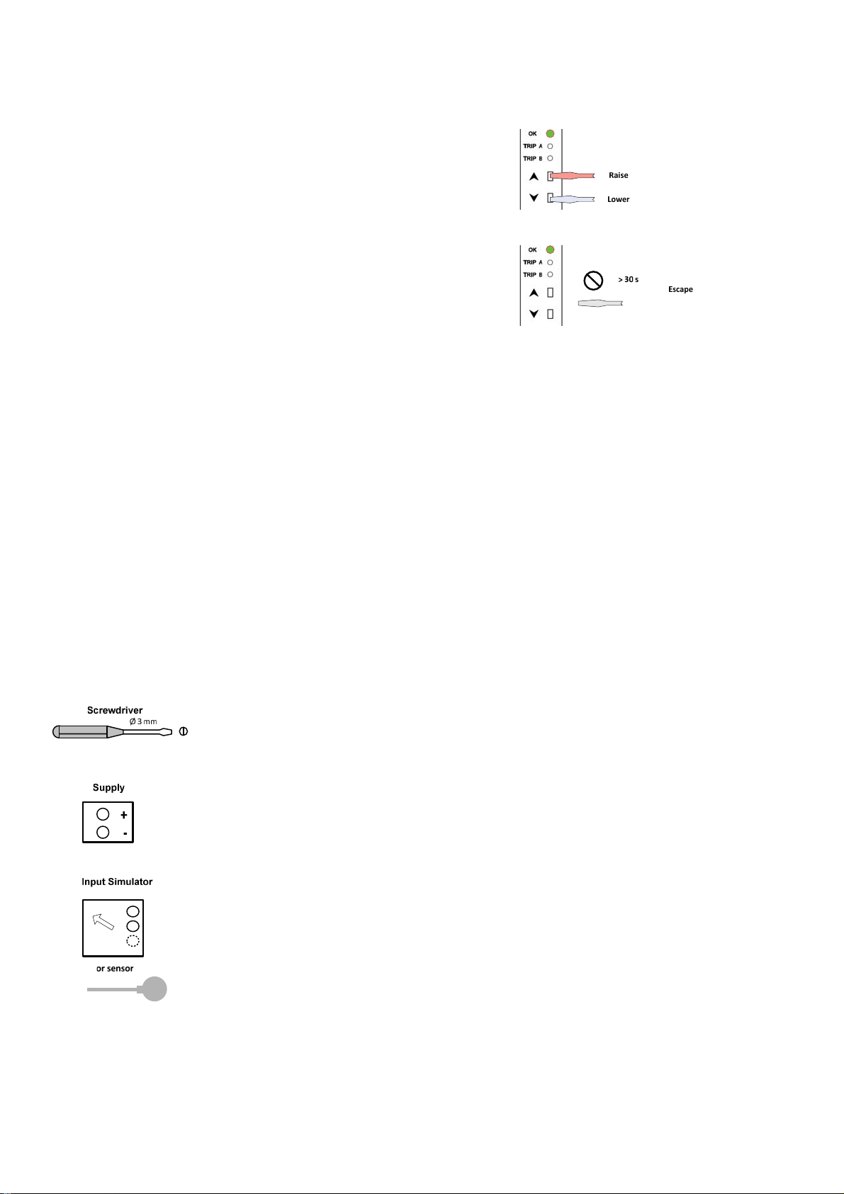
3.0 Trim output current by pressing either the raise or lower button, single click to step
Omega TXDIN1700 User Guide V1
3
advance, or press continuously to auto advance.
4.0 Once trim is complete allow 30 seconds with no button press, the transmitter will time
out and return to normal operation.
SENSOR FAULT CONDITIONS
TC or RTD Input.
Analogue output.
On loss of the input signal the TXDIN1700 w
Rela
output.
y
The relays will trip (change state from the normal condition) on loss of the input signal, unless set to the off position.
Process Input.
Analogue output.
Loss of the input signal does not affect the output in the same way as with TC or RTD.
With process inputs a lost signal will be seen as a process value scaled to the equivalent of a zero electrical input.
If the process value is below the process low range the output will go to its low scale value (less approximately 10% of the output range)
ill go into burnout condition, this is selectable (high, low, or user).
Relay output.
Only with low alarm or low control will the relays trip (change state from the normal condition) on under range/loss of input signal.
USER RANGE CONFIGURATION
This function allows two point manual configuration of the re-transmission current (voltage) at low and high range against
a live input signal. This is useful for on-site configuration, example with a slide wire input the user manually positions the
slide at both low and high positions and configure the unit to operate over the range. Configuration is achieved using
either the raise (span) or lower (offset) buttons.
To operate this function must first be selected using the software configuration tool. The operator may lock this function
(once set) by turning off the function.
METHOD
1.0 Connect transmitter to a suitable input simulator or sensor. Connect supply, turn supply on, set input to either
offset or span calibration point.
2.0 To enter configuration, set input to
desired high or low setting and wait 10 seconds.
Press and hold raise (high) or lower (low) button on
for > 2 s to enter.
The ok LED will then start to flash at a slow rate
(low) or fast rate (high).
3.0 Once the menu has been entered, quickly
(within 1 second) apply a single press to the raise
(high) or lower (low) button to store setting.
To abort configuration, allow config to time out by not
pressing buttons for 5 seconds.
Page 6

OUTPUT DAMPING
Omega TXDIN1700 User Guide V1
4
User adjustable damping of the analogue output is provided for both rising and falling signals. The adjustable range is (0 to 250) second for a ( 0 to 20)
mA or (0 to 10) V swing.
To calculate the maximum rate of change of the output signal divide 20 mA (10 V) by the damping setting, example if the damping is set to 100 seconds
the mA output will change at a maximum rate of (20/100) = 0.2 mA /Second. Use USB_LINK software to configure damping setting.
Page 7
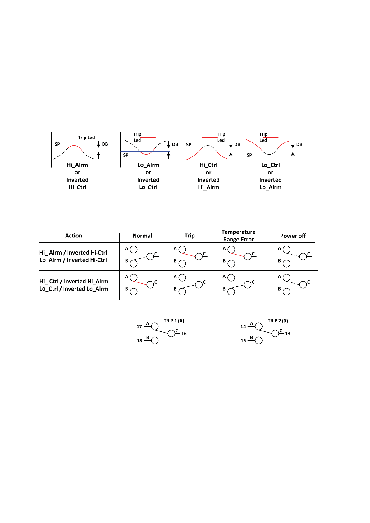
TRIP OUTPUTS
Omega TXDIN1700 User Guide V1
5
Dual trip change over contacts are available. The contacts are rated at 240 V ac 1 A (Non inductive) 30 V DC 1 A. An external snubber network is
recommended when switching inductive circuits. Please ensure the snubber network is rated for the application. Four actions are provided, as detailed
in the diagram below. The Alarm actions may also be used for inverted control applications, example the high alarm action can be used to control a
cooling fan when used to control the temperature of a heat source. Adjustable setpoint and deadband are provided together with adjustable on and off
delays for each trip. The delay range is (0 to 250) Seconds.
Page 8
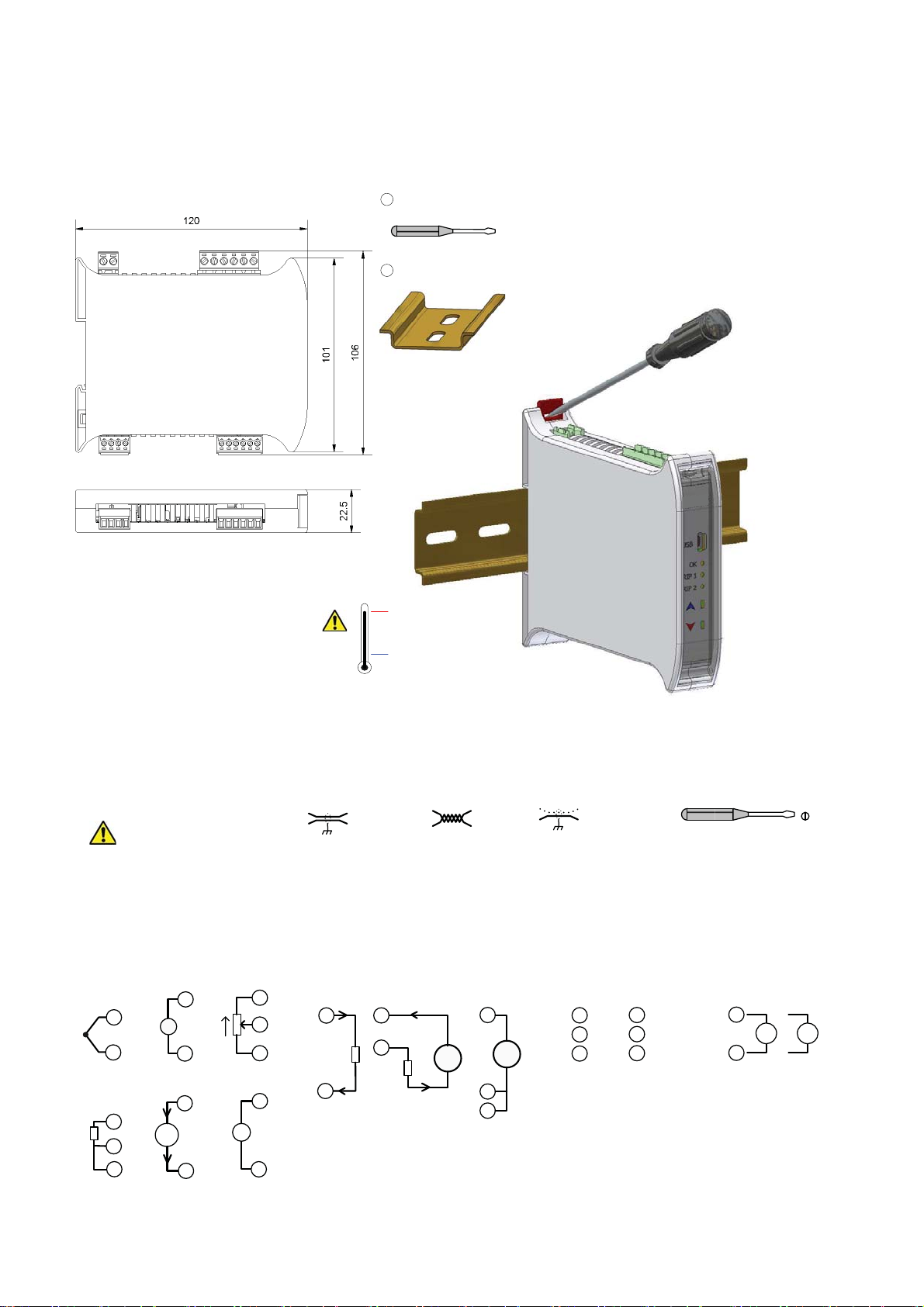
MECHANICAL INSTALLATION
Omega TXDIN1700 User Guide V1
6
ϭϭϭϮ ϭϯϭϰϭϱϭϲϭϳϭϴ
ϭϬϵϴϳ ϲϱϰϯϮϭ
ůůŝŵĞŶƐŝŽŶƐŝŶŵŵ
DKhEd/E'
^ĐƌĞǁĚƌŝǀĞƌ
ϭ
Ϯ
EϲϬϳϭϱ/EZ/>
нϳϬΣDĂdž
Tϯŵŵ
(QFORVXUH
6W\OH ',15DLO0RXQW
0DWHULDO %OHQG3&$ %6 VHOIH[WLQJXLVKLQJ
7HUPLQDOV 6FUHZWHUPLQDO
&DEOH PP 0D[
&RORXU *UH\
dŽĨŝƚŽƌƌĞůĞĂƐĞŵŽĚƵůĞ
/ŶƐĞƌƚƐĐƌĞǁĚƌŝǀĞƌŝŶƚŽ
ƐůŽƚĂŶĚůĞǀĞƌůĂƚĐŚ
ĂǁĂLJĨƌŽŵďŽĚLJ
ELECTRICAL INSTALLATION
dhZEK&&^hWW>z&KZtKZ</E'KE
Ez>dZ/>KEEd/KE
,1387&211(&7,21
)RUFDEOHOHQJWK0HWUHVQRVFUHHQRU
WZLVWHGSDLUUHTXLUHG
7KHUPRFRXSOHLQSXWVPXVWXVH FRUUHFW
FRPSHQVDWLRQFDEOH
37LQSXWVDOOWKUHHZLUHVPXVW EHHTXDO
OHQJWKUHVLVWDQFH
0D[LQSXWFDEOHOHQJWK PHWUHV
7HPSHUDWXUH 3URFHVV
н
Ͳ
d
WdϭϬϬ
Ϯ
ϰ
ϱ
Ϯ
ϯ
н
s
Ͳ
н
ddž
Ͳ
dƌĂŶƐŵŝƚƚĞƌ
sŵs
Ϯ
ϰ
^ůŝĚĞtŝƌĞ
ϭ
ŵ
ϯ
ŵ^ĞŶƐĞ
$PELHQW5DQJH
6FUHHQHG&DEOH 7ZLVWHG3DLU&DEOH
Ͳ ϮϬΣDŝŶ
7&&RPSHQVDWLRQ&DEOH
6FUHZGULYHU
Tϯŵŵ
6FUHHQHG
$1$/2*8(28738 7&211(&7,21
)RUFDEOHOHQJWKPHWUHVQRVF UHHQRUWZLVWHG
SDLUUHTXLUHG
8VHWZLVWHGSDLURUVFUHHQHG IRUFXUUHQWRXWSXW
WRPHWUHV
9ROWDJHRXWSXWXVHVFUHHQHGFDEOHVWR
PHWUHVFDEOHOHQJWKV! PHWUHVQRWDGYLVHG
ϴ
ϵ
>ŽĂĚ
&XUUHQW
([WHUQDOO\
3RZHUHG
9ROWDJH
ϳ
н
sƐ
sŽƵƚ
Ͳ
ϭϬ
ϴ
&XUUHQW
,QWHUQDO
ϲ
Ϯ
ϰ
ϯ
3RZHUHG
ϳ
>ŽĂĚ
ϴ
н
75,3287387
&211(&7,21
7ULSRXWSXWVDUHLVRODWHG
IURPHDFKRWKHU
0D[VZLWFKLQJFXUUHQW$
#9DF$#9GF
1RQ,QGXFWLYH
75,3%
ϭϯ
н
ϭϰ
ϭϱĂď
Ͳ
75,3$
Đ
ϭϲ
Đ
Ă
ϭϳ
ď
ϭϴ
6833/<&211(&7,21
6XSSO\LQSXWLVQRWSRODULW\
VHQVLWLYH
0D[VXSSO\9DFRU
9GF
ϭϭ
ϭϮ
н
ĂĐ ĚĐ
Ͳ
Ͳ
ϰ
Page 9

WARRANTY/DISCLAIMER
OMEGA ENGINEERING, INC. warrants this unit to be free of defects in materials and workmanship for a
period of 61 months from date of purchase. OMEGA’s WARRANTY adds an additional one (1) month grace
period to the normal five (5) year product warranty to cover handling and shipping time. This ensures
that OMEGA’s customers receive maximum coverage on each product.
If the unit malfunctions, it must be returned to the factory for evaluation. OMEGA’s Customer Service
Department will issue an Authorized Return (AR) number immediately upon phone or written request.
Upon examination by OMEGA, if the unit is found to be defective, it will be repaired or replaced at no
charge. OMEGA’s WARRANTY does not apply to defects resulting from any action of the purchaser,
including but not limited to mishandling, improper interfacing, operation outside of design limits,
improper repair, or unauthorized modification. This WARRANTY is VOID if the unit shows evidence of
having been tampered with or shows evidence of having been damaged as a result of excessive corrosion;
or current, heat, moisture or vibration; improper specification; misapplication; misuse or other operating
conditions outside of OMEGA’s control. Components in which wear is not warranted, include but are not
limited to contact points, fuses, and triacs.
OMEGA is pleased to offer suggestions on the use of its various products. However,
OMEGA neither assumes responsibility for any omissions or errors nor assumes liability for
any damages that result from the use of its products in accordance with information provided
by OMEGA, either verbal or written. OMEGA warrants only that the parts manufactured by the
company will be as specified and free of defects. OMEGA MAKES NO OTHER WARRANTIES OR
REPRESENTATIONS OF ANY KIND WHATSOEVER, EXPRESSED OR IMPLIED, EXCEPT THAT OF
TITLE, AND ALL IMPLIED WARRANTIES INCLUDING ANY WARRANTY OF MERCHANTABILITY
AND FITNESS FOR A PARTICULAR PURPOSE ARE HEREBY DISCLAIMED. LIMITATION OF
LIABILITY: The remedies of purchaser set forth herein are exclusive, and the total liability of
OMEGA with respect to this order, whether based on contract, warranty, negligence,
indemnification, strict liability or otherwise, shall not exceed the purchase price of the
component upon which liability is based. In no event shall OMEGA be liable for
consequential, incidental or special damages.
CONDITIONS: Equipment sold by OMEGA is not intended to be used, nor shall it be used: (1) as a “Basic
Component” under 10 CFR 21 (NRC), used in or with any nuclear installation or activity; or (2) in medical
applications or used on humans. Should any Product(s) be used in or with any nuclear installation or
activity, medical application, used on humans, or misused in any way, OMEGA assumes no responsibility
as set forth in our basic WARRANTY/DISCLAIMER language, and, additionally, purchaser will indemnify
OMEGA and hold OMEGA harmless from any liability or damage whatsoever arising out of the use of the
Product(s) in such a manner.
RETURN REQUESTS/INQUIRIES
Direct all warranty and repair requests/inquiries to the OMEGA Customer Service Department. BEFORE
RETURNING ANY PRODUCT(S) TO OMEGA, PURCHASER MUST OBTAIN AN AUTHORIZED RETURN (AR)
NUMBER FROM OMEGA’S CUSTOMER SERVICE DEPARTMENT (IN ORDER TO AVOID PROCESSING
DELAYS). The assigned AR number should then be marked on the outside of the return package and on any
correspondence.
The purchaser is responsible for shipping charges, freight, insurance and proper packaging to prevent
breakage in transit.
FOR WARRANTY RETURNS, please have the
following information available BEFORE contacting
OMEGA:
1. Purchase Order number under which the product
was PURCHASED,
2. Model and serial number of the product under
warranty, and
3. Repair instructions and/or specific problems
relative to the product.
OMEGA’s policy is to make running changes, not model changes, whenever an improvement is possible. This affords our
customers the latest in technology and engineering.
OMEGA is a registered trademark of OMEGA ENGINEERING, INC.
© Copyright 2016 OMEGA ENGINEERING, INC. All rights reserved. This document may not be copied, photocopied,
reproduced, translated, or reduced to any electronic medium or machine-readable form, in whole or in part, without the prior
written consent of OMEGA ENGINEERING, INC.
FOR NON-WARRANTY REPAIRS, consult
OMEGA for current repair charges. Have
the following information available BEFORE
contacting OMEGA:
1. Purchase Order number to cover the COST
of the repair,
2. Model and serial number of the product, and
3. Repair instructions and/or specific problems
relative to the product.
Page 10

Where Do I Find Everything I Need for
Process Measurement and Control?
OMEGA…Of Course!
Shop online at omega.com
TEMPERATURE
MU
Thermocouple, RTD & Thermistor Probes, Connectors,
Panels & Assemblies
MU
Wire: Thermocouple, RTD & Thermistor
MU
Calibrators & Ice Point References
MU
Recorders, Controllers & Process Monitors
MU
Infrared Pyrometers
PRESSURE, STRAIN AND FORCE
MU
Transducers & Strain Gages
MU
Load Cells & Pressure Gages
MU
Displacement Transducers
MU
Instrumentation & Accessories
FLOW/LEVEL
MU
Rotameters, Gas Mass Flowmeters & Flow Computers
MU
Air Velocity Indicators
MU
Turbine/Paddlewheel Systems
MU
Totalizers & Batch Controllers
SM
pH/CONDUCTIVITY
MU
pH Electrodes, Testers & Accessories
MU
Benchtop/Laboratory Meters
MU
Controllers, Calibrators, Simulators & Pumps
MU
Industrial pH & Conductivity Equipment
DATA ACQUISITION
MU
Communications-Based Acquisition Systems
MU
Data Logging Systems
MU
Wireless Sensors, Transmitters, & Receivers
MU
Signal Conditioners
MU
Data Acquisition Software
HEATERS
MU
Heating Cable
MU
Cartridge & Strip Heaters
MU
Immersion & Band Heaters
MU
Flexible Heaters
MU
Laboratory Heaters
ENVIRONMENTAL
MONITORING AND CONTROL
MU
Metering & Control Instrumentation
MU
Refractometers
MU
Pumps & Tubing
MU
Air, Soil & Water Monitors
MU
Industrial Water & Wastewater Treatment
MU
pH, Conductivity & Dissolved Oxygen Instruments
M5636/1216
 Loading...