

Page 1
omega.com
e-mail: [email protected]
For latest product manuals:
omegamanual.info
User’s Guide
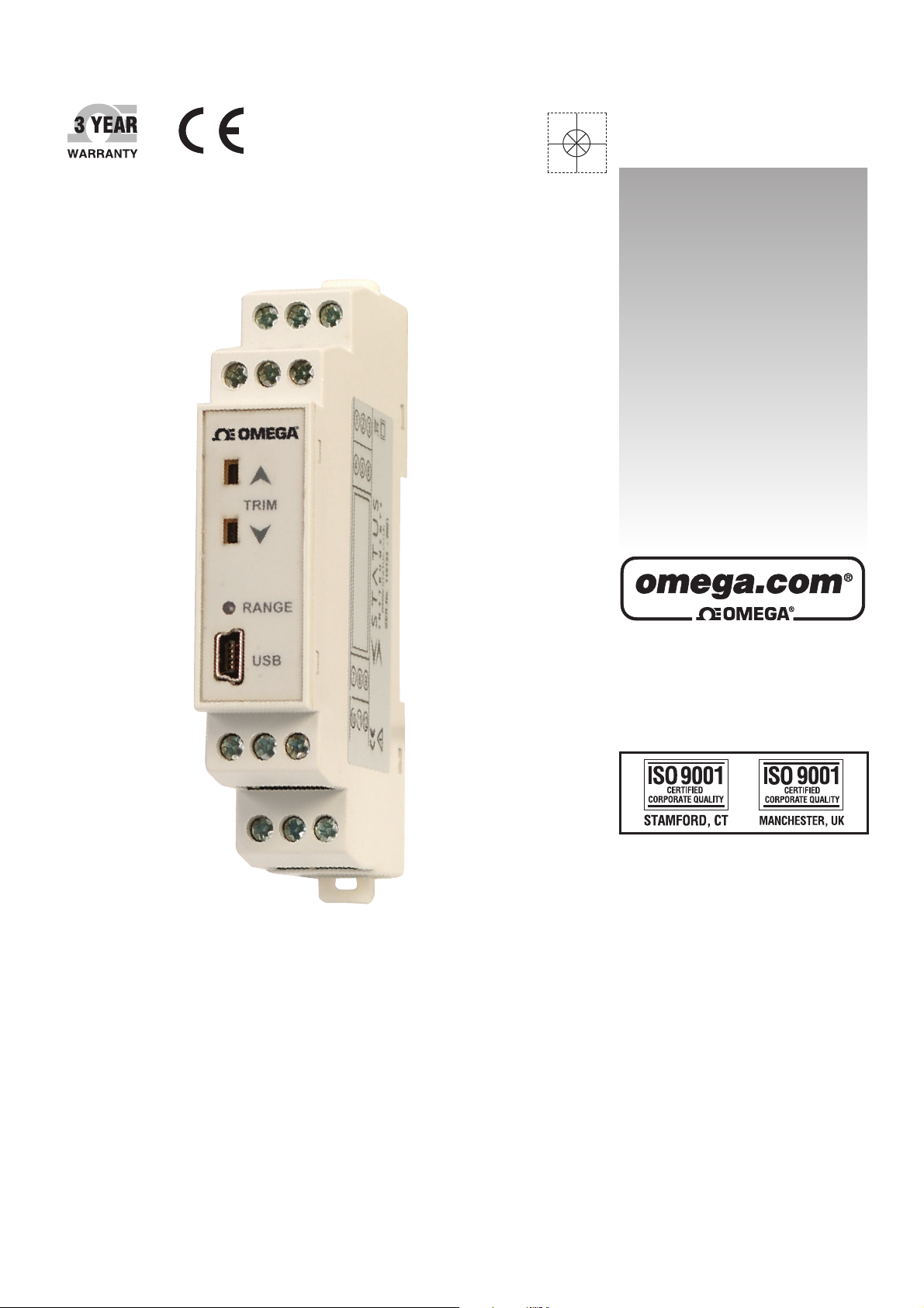
TXDIN1610
Universal DIN Rail Transmitter
TXDIN1620
Universal DIN Rail Transmitter With
3-Wire Insulated Wire Output
TXDIN1630
Universal DIN Rail Trip Amplifier
®
Shop online at
MADE IN UNITED KINGDOM
Page 2

Servicing North America:
U.S.A.: One Omega Drive, P.O. Box 4047
ISO 9001 Certified Stamford, CT 06907-0047
TEL: (203) 359-1660
FAX: (203) 359-7700
e-mail: [email protected]
Canada: 976 Bergar
Laval (Quebec) H7L 5A1, Canada
TEL: (514) 856-6928
FAX: (514) 856-6886
e-mail: [email protected]
For immediate technical or application assistance:
U.S.A. and Canada: Sales Service: 1-800-826-6342/1-800-TC-OMEGA
®
Customer Service: 1-800-622-2378/1-800-622-BEST
®
Engineering Service: 1-800-872-9436/1-800-USA-WHEN
®
Mexico: En Espan˜ ol: (001) 203-359-7803
FAX: (001) 203-359-7807
e-mail: [email protected]
[email protected]
Servicing Europe:
Czech Republic: Frystatska 184, 733 01 Karviná, Czech Republic
TEL: +420 (0)59 6311899
FAX: +420 (0)59 6311114
Toll Free: 0800-1-66342
e-mail: [email protected]
Germany/Austria: Daimlerstrasse 26, D-75392 Deckenpfronn, Germany
TEL: +49 (0)7056 9398-0
FAX: +49 (0)7056 9398-29
Toll Free in Germany: 0800 639 7678
e-mail: [email protected]
United Kingdom: One Omega Drive, River Bend Technology Centre
ISO 9001 Certified Northbank, Irlam, Manchester
M44 5BD United Kingdom
TEL: +44 (0)161 777 6611
FAX: +44 (0)161 777 6622
Toll Free in United Kingdom: 0800-488-488
e-mail: [email protected]
OMEGAnet®Online Service Internet e-mail
omega.com [email protected]
It is the policy of OMEGA Engineering, Inc. to comply with all worldwide safety and EMC/EMI
regulations that apply. OMEGA is constantly pursuing certification of its products to the European New
Approach Directives. OMEGA will add the CE mark to every appropriate device upon certification.
The information contained in this document is believed to be correct, but OMEGA accepts
no liability for any errors it contains, and reserves the right to alter specifications without notice.
WARNING: These products are not designed for use in, and should not be used for, human applications.
Page 3
®
1
ENGINEERING, INC.
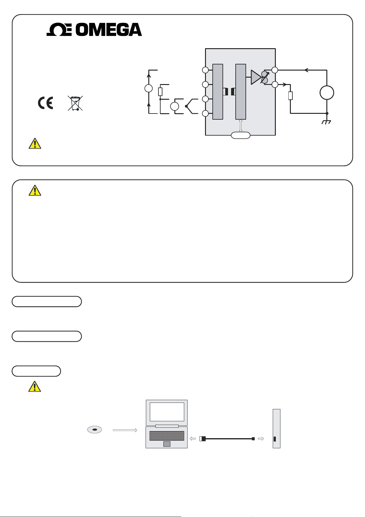
TXDIN1610 USER GUIDE
DIN RAIL MOUNTED TRANSMITTER
+
10
0
+
5
UNIVERSAL INPUT
TWO WIRE (4 to 20) mA OUTPUT
mA
-
PT10
0
m
V
Universal
Input
9
++
8
7
--
USB
4
-
Loop
Resistor
2 Wire (4-20) mA
Output
Important - Please read this document before any installing.
Every effort has been taken to ensure the accuracy of this document, however we do not accept responsibility for damage, injury, loss or expense resulting from errors and omissions, and we reserve the right of amendment without notice.
IMPORTANT - CE & SAFETY REQUIREMENTS
Product must be DIN rail mounted, inside a suitable enclosure providing environmental protection to IP65 or greater.
To maintain CE EMC requirements, input wires must be less than 30 metres.
The product contains no serviceable parts , or internal adjustments. no attempt must be made to repair this product. Faulty units must be returned to supplier for repair.
This product must be installed by a qualified person. All electrical wiring must be carried out in accordance with the appropriate regulations for the place of installation.
Before attempting any electrical connection work, please ensure all supplies are switched off.
ABSOLUTE MAXIMUM OPERATING CONDITIONS:-
Supply Voltage ± 30 V dc (Protected for over voltage and reverse connection)
Current with over voltage ± 200 mA
Input Voltage ± 5 V between any terminals
Input Current ± 100 mA between terminals 7 & 10
Ambient Temperature (-30 to 75) °C Humidity (10 to 95) % RH (Non condensing)
+
V
s
-
PRODUCT SPECIFICATION
Please refer to the product data sheet for full specification, available to down load at www.omegamanual.info.
RECEIVE AND UNPACKING
Please inspect the packaging and instrument thoroughly for any signs of transit damage. If the instrument has been damaged, please notify your supplier immediately.
CONFIGURATION
IMPORTANT The TXDIN1610 can be configured whilst connected and powered, but a portable battery powered computer must be used to avoid the effects of ground loops.
TXDIN1610
M-CONFIG SOFTWARE
Disk
The following parameter can be configured by simply entering as prompted by the software package.
· Input type (K, J, E, N,T, R, S, mV, PT100, mA)
· Low range
· High range
· Units (°C, °F, mV, mA)
· Burnout (direction of output current on sensor burnout)
· User Trim (option to lock out front panel trim function)
COMPUTER
USB CABLE
Factory default:
Input type = P
Units = °C
High Range = 100
Low Range = 0
Burnout = UPSCALE
User Trim = ON
Page 4
2 0.0 0 0
2 0 .0 0 0
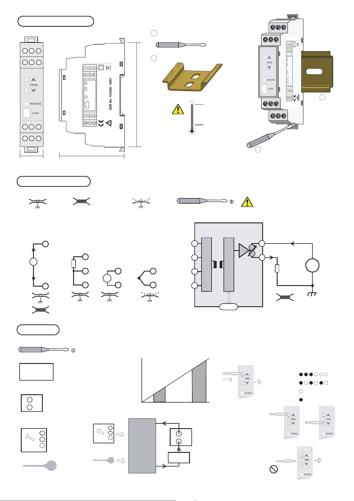
MECHANICAL INSTALLATION
2
1 2 3
4 5 6
1
2
987
11 1210
56.4 mm17.5 mm
ELECTRICAL INSTALLATION
Screened Cable Twisted Pair Cable
MOUNTING
1
Screw driver
2
EN50022 DIN RAIL
90 mm
TXDIN1620 Enclosure
Style DIN 43880 (1 module width)
Material Polyamide 6.6 self extinguishing
Terminals Screw terminal
Cable 2.5 mm Max
Colour Grey
TC Compensation Cable
Screened
Ø 3 mm
Screw Driver
+ 70 °C Max
- 20 °C Min
Ø 3mm
2
m
m
3
Ø
1
TURN OFF SUPPLY BEFORE W ORKING
ON ANY ELECTRICAL CONNECTION
To fit or release module
Insert screw driver into
slot and lever latch
away from body
mA
USER TRIM
Screw Driver
Digital mA meter
Power supply (24V dc)
Input Simulator
or sensor
UNIVERSAL INPUT CONNECTION
For cable length < 3 Metres no screen or twist pair required.
Thermocouple inputs must use correct compensation cable.
PT100 inputs all three wire must be equal length (resistance).
+
-
Use recommended types for cable length (3 to 30) metres.
10
PT10
0
9
8
8
m
7
7
V
7 7
-
1
0
T/C
++
8
-
9
8
7
0
US
B
SUPPLY (Vs) = (11 to 30) V dc
MAX LOAD Ohms = (Vs - 11) / 0.021
+
5
4
-
LOAD
OUTPUT
2 Wire (4-20) mA
+
V
s
-
Max cable length 1000 metres
Use twisted pair cable > 30 metres
User trim function allows manual adjustment of the output current, this
is useful for minor calibration adjustment or trimming out any sensor
error, ± 5% of range adjustment is available at both offset and span.
Ø 3mm
+
-
Raise and lower buttons are provided on the front panel, of the
transmitter, accessed using a 3 mm flat blade screw driver. Insert the
screw driver into the appropriate slot to operate the button. The button
has a click action.
The transmitter will
automatically detect the
correct trim point (offset or
span) based on the output
current drive. Offset will be
trimmed when the current
is between (3.8 to 6) mA,
span when the current is
between (18 to 22) mA. No
trim action occurs at any
other current.
offset
3.8 6
span
18
+
METHOD
1.0 Connect transmitter to a suitable input simulator or sensor.
Connect output to a 24V dc supply, connecting a digital mA
current meter in series with the output. Turn supply on, set
input to either offset or span calibration point.
2.0 Enter trim menu by pressing "raise" button for > two seconds.
When the trim menu is open the range LED will flash :-
Enter
> 3 s
22
mA
3.0 Trim output current
by pressing either the
raise or lower button,
single click to step
advance , or press
continuously to auto
advance.
Range LED will indicate Trim action
Offset slow toggle
Span fast toggle
Out of trim range
Input out of range
Raise
Lower
-
or
4.0 Once trim is complete
allow 30 seconds with no
button press, the
transmitter will time out
and return to normal
operation.
Escape
> 30 s
Page 5
IMPORTANT - CE & SAFETY REQUIREMENTS
Product must be DIN rail mounted, inside a suitable enclosure providing environmental protection to IP65 or greater.
To maintain CE EMC requirements , input and supply wires must be less than 30 metres.
Dc supply must be derived from a local supply and not a distribution system.
The product contains no serviceable parts , or internal adjustments. no attempt must be made to repair this product. Faulty units must be returned to supplier for repair.
This product must be installed by a qualified person. All electrical wiring must be carried out in accordance with the appropriate regulations for the place of installation.
Before attempting any electrical connection work, please ensure all supplies are switched off.
ABSOLUTE MAXIMUM OPERATING CONDITIONS:-
Supply Voltage ± 30 V dc (Protected for over voltage and reverse connection)
Current with over voltage ± 200 mA
Input Voltage ± 5 V between any terminals
Input Current ± 100 mA between terminals 7 & 10
Ambient Temperature (-30 to 75) °C Humidity (10 to 95) % RH (Non condensing)
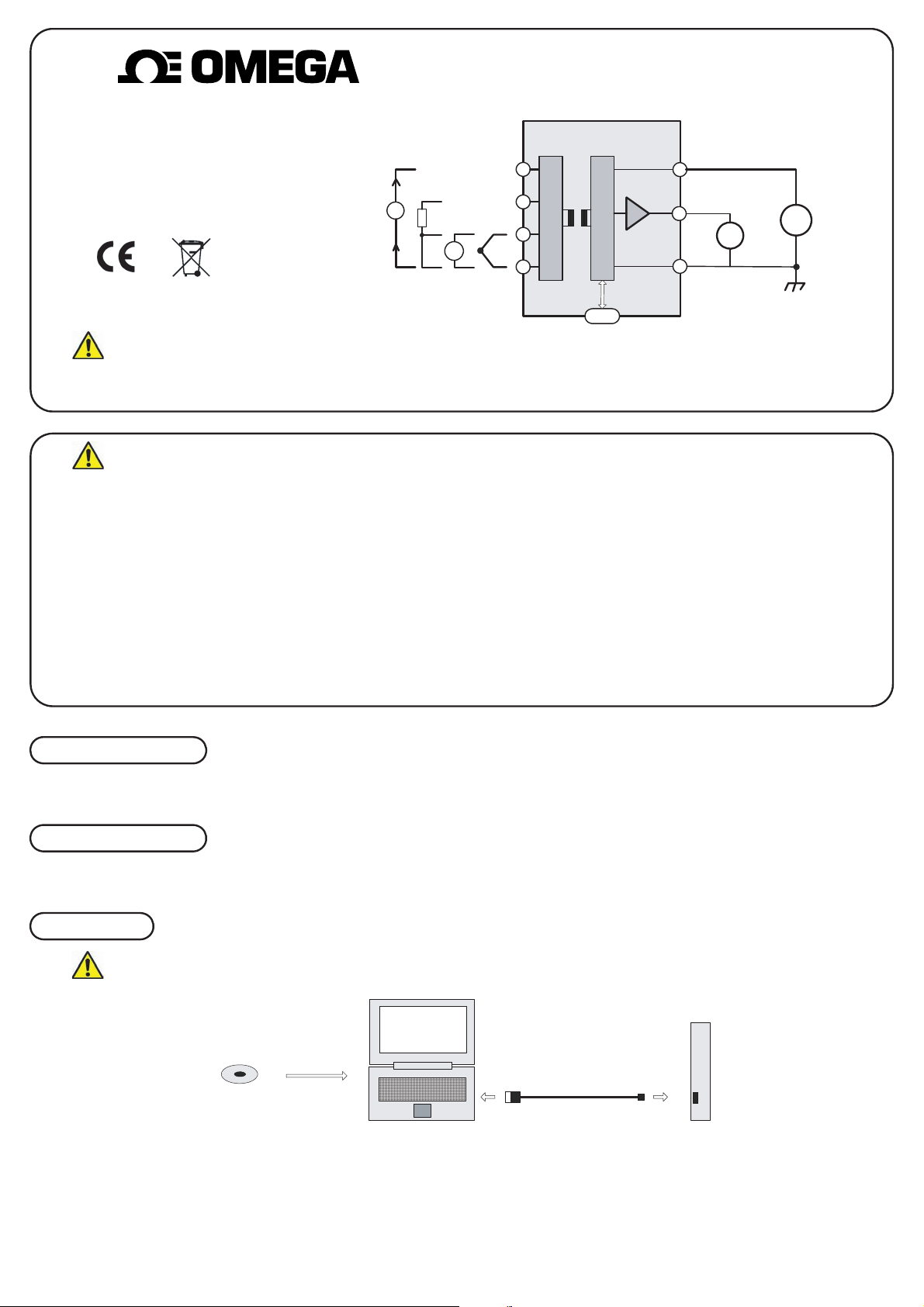
TXDIN1620 USER GUIDE
DIN RAIL MOUNTED CONDITIONER
UNIVERSAL INPUT
THREE WIRE VOLTAGE OUTPUT
Every effort has been taken to ensure the accuracy of this document, however we do not accept responsibility for damage, injury, loss or expense resulting from errors and omissions, and we reserve the right of amendment without notice.
Important - Please read this document before any installing.
PT100
mA
+
-
mV
++
--
Universal Input
10
9
8
7
Three Wire Voltage Output
6
5
V s
USB
+
-
+
-
4
Vo
+
-
PRODUCT SPECIFICATION
RECEIVE AND UNPACKING
CONFIGURATION
Please refer to the product data sheet for full specification, available to down load at www.omegamanual.info.
Please inspect the packaging and instrument thoroughly for any signs of transit damage. If the instrument has been damaged, please notify your supplier immediately.
TXDIN1620
M-CONFIG SOFTWARE
USB CABLE
Disk
COMPUTER
The following parameter can be configured by simply entering as prompted by the software package.
· Input type (K, J, E, N, T, R, S, mV, PT100, mA)
· Low range
· High range
· Units (°C, °F, mV, mA)
· Burnout (direction of output current on sensor burnout)
· Output Range (0 to 10), (0 to 5), (0 to 1), (1 to 5), and (2 to 10) V
· User Trim (option to lock out front panel trim function)
Factory default:
Input type = P
Units = °C
High Range = 100
Low Range = 0
Burnout = UPSCALE
Output range = (0 to 10) V
User Trim = ON
IMPORTANT The TXDIN1620 can be configured whilst connected and powered, but a portable battery powered computer must be used to avoid the effects of ground loops.
ENGINEERING, INC.
3
Page 6
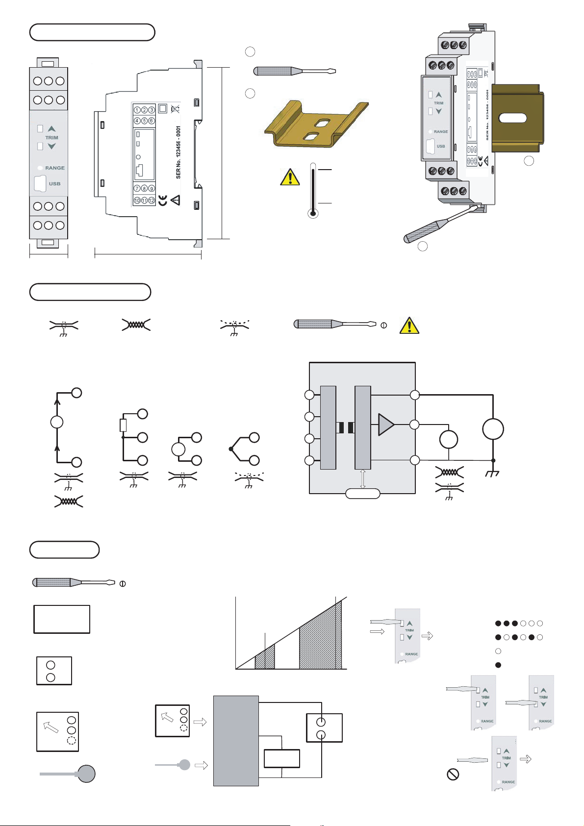
MECHANICAL INSTALLATION
10.0 0 0
1 0.0 0
4
1 2 3
4 5 6
1
2
987
11 1210
56.4 mm17.5 mm
ELECTRICAL INSTALLATION
Screened Cable Twisted Pair Cable
MOUNTING
1
Screw driver
2
EN50022 DIN RAIL
90 mm
TXDIN1620 Enclosure
Style DIN 43880 (1 module width)
Material Polyamide 6. self extinguishing
Terminals Screw terminal
Cable 2.5 mm Max
Colour Grey
TC Compensation Cable
Screened
Ø 3 mm
Screw Driver
+ 70 °C Max
- 20 °C Min
Ø 3 mm
2
m
m
3
Ø
1
TURN OFF SUPPLY BEFORE WORKING
ON ANY ELECTRICAL CONNECTION
To fit or release module
Insert screw driver into
slot and lever latch
away from body
USER TRIM
Screw Driver
Digital Voltage meter
Power supply (24 V dc)
Input Simulator
or sensor
mA
UNIVERSAL INPUT CONNECTION
For cable length < 3 Metres no screen or twist pair required.
Thermocouple inputs must use correct compensation cable.
PT100 inputs all three wire must be equal length (resistance).
+
Use recommended types for cable length (3 to 30) metres.
10
PT10
0
9
8
8
T/C
++
8
m
7
-
7
V
7 7
-
-
TXDIN1620
10
9
8
7
USB
Three Wire Voltage Output
Supply (Vs ) (15 to 28) V dc
Output (Vo) (0 to 10) V max
O/p drive Current 2 mA
+
6
5
+
Vo
-
4
-
+
V s
-
OUTPUT
Three wire voltage
Max cable length 30 metres
Use twisted pair cable or screened > 3 metres
User trim function allows manual adjustment of the output current, this
is useful for minor calibration adjustment or trimming out any sensor
error, ± 5% of range adjustment is available at both offset and span.
Ø 3 mm
+
-
Raise and lower buttons are provided on the front panel, of the
conditioner, accessed using a 3 mm flat blade screw driver. Insert the
screw driver into the appropriate sl ot to operate the button. The button
has a click action.
The conditioner will
automatically detect the
correct trim point (offset or
span) based on the output
current drive. Offset will be
trimmed when the output
voltage is within ± 0.1 V of
offset output, span when
the output voltage is within
(50 to 105) % of output
range.
TXDIN1620
offset
offset
± 0.1 V
50%
Span
span
METHOD
1.0 Connect input simulator or sensor. Connect supply to a 24 V
dc, connecting a digital volt current meter to output. Turn
supply on, set input to either offset or span calibration point.
2.0 Enter trim menu by pressing "raise" button for > two seconds.
When the trim menu is open the range LED will flash :-
Enter
105
%
3.0 Trim output voltage
Span
by pressing either the
raise or lower button,
single click to step
advance , or press
continuously to auto
+
advance.
> 3 s
Range LED will indicate Trim action
Offset slow toggle
Span fast toggle
Out of trim range
Input out of range
Raise
Lower
-
or
4.0 Once trim is complete
allow 30 seconds with no
button press, the
cobnditioner will time out
and return to normal
operation.
Escape
> 30 s
Page 7
IMPORTANT - CE & SAFETY REQUIREMENTS
This product is suitable for enviroment Installation category II pollution degree.
The product is classed as "PERMANENTLY CONNECTED EQUIPMENT".
Product must be DIN rail mounted, inside a suitable enclosure providing environmental protection to IP65 or greater.
Dc supply must be derived from a local supply and not a distribution system.
Max relay contact rating 250 V AC @ 1 a (30 V DC @ 1A). Any circuit connected to a contact must be fused with a 2A (T) fuse.
To maintain CE EMC requirements , input and supply wires must be less than 30 metres.
The product contains no serviceable parts, or internal adjustments. no attempt must be made to repair this product. Faulty uni ts must be returned to supplier for repair.
This product must be installed by a qualified person. All electrical wiring must be carried out in accordance with the appropriate regulations for the place of installation.
Before attempting any electrical connection work, please ensure all supplies are switched off.
ABSOLUTE MAXIMUM OPERATING CONDITIONS:-
Supply Voltage ± 30 V dc (Protected for over voltage and reverse connection)
Current with over voltage ± 200 mA
Input Voltage ± 5 V between any terminals
Input Current ± 100 mA between terminals 7 & 10
Ambient Temperature (-30 to 75) °C Humidity (10 to 95) % RH (Non condensing)
Every effort has been taken to ensure the accuracy of this document, however we do not accept responsibility for damage, injury, loss or expense resulting from errors and omissions, and we reserve the right of amendment without notice.
Important - Potentially Hazardous situations. Persons responsible for the installation and operation of this equipment must be fully aware of all
aspects of this guide. Failure to follow the instructions can cause severe injuries and damage.
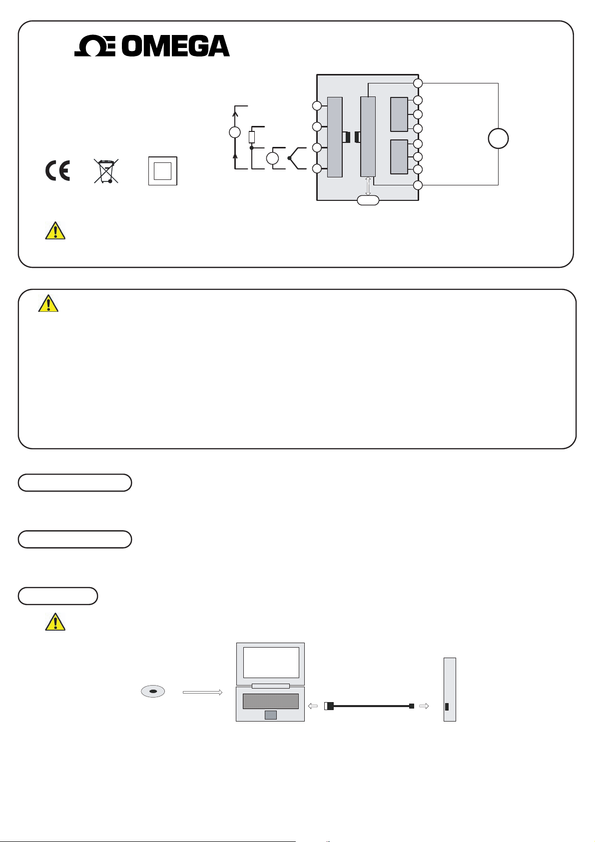
The following parameter can be configured by simply entering as prompted by the software package.
· Input type (K, J, E, N, T, R, S, mV, PT100, mA)
· Setpoint Trip A & B
· Hysterisis Trip A & B
· Units (°C, °F, mV, mA)
· Trip A & B Level (High or Low)
PRODUCT SPECIFICATION
mA
Universal Input
10
9
8
7
mV
++
--
PT100
+
-
Dual trip Output
TXDIN1630
1
2
V s
USB
+
-
+
-
3
12
4
5
6
n/o
n/c
c
n/o
n/c
c
Trip B
Trip A
11
TXDIN1630 USER GUIDE
DIN RAIL MOUNTED TRIP
AMP
UNIVERSAL INPUT
DUAL Form C OUTPUT
RECEIVE AND UNPACKING
CONFIGURATION
Please refer to the product data sheet for full specification, available to down load at www.omegamanual.info.
Please inspect the packaging and instrument thoroughly for any signs of transit damage. If the instrument has been damaged, please notify your supplier immediately.
TXDIN1630
M-CONFIG SOFTWARE
USB CABLE
Disk
COMPUTER
Factory default:
Input type = P
Units = °C
Trip A = H
Setpoint Trip A = 50
Hysterisis Trip A = 1
Trip B = H
Setpoint Trip B = 50
Hysterisis Trip B = 1
IMPORTANT The TXDIN1630 can be configured whilst connected and powered, but a portable battery powered computer must be used to avoid the effects of ground loops.
ENGINEERING, INC.
5
Page 8
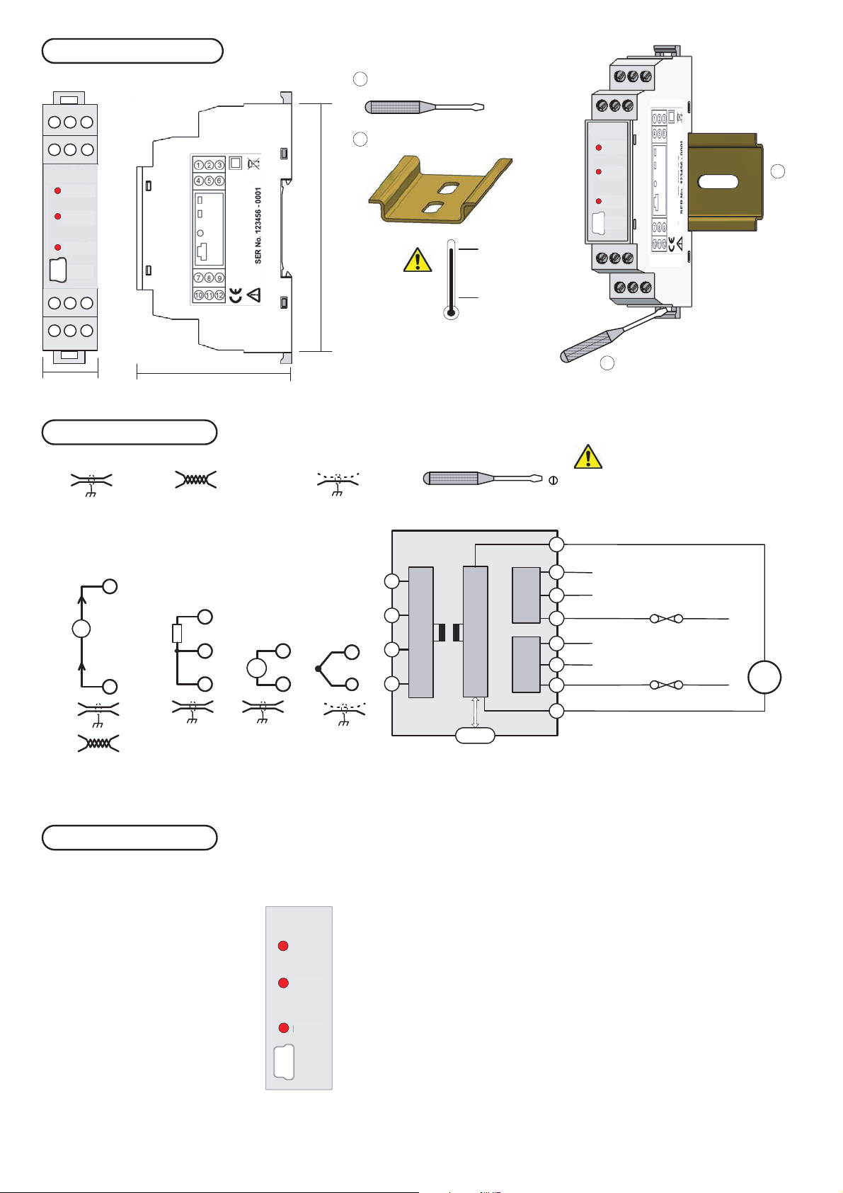
MECHANICAL INSTALLATION
6
1 2 3
4 5 6
TRIP A
TRIP B
90 mm
MOUNTING
Screw driver
1
2
EN50022 DIN RAIL
Ø 3 mm
TRIP A
TRIP B
RANG
2
E
USB
RANGE
1
USB
2
987
11 1210
17.5 mm
56.4 mm
ELECTRICAL INSTALLATION
Screened Cable Twisted Pair Cable
UNIVERSAL INPUT CONNECTION
For cable length < 3 Metres no screen or twist pair required.
Thermocouple inputs must use correct compensation cable.
PT100 inputs all three wire must be equal length (resistance).
Use recommended types for cable length (3 to 30) metres.
+
10
PT10
0
9
mA
8
7
-
7
TC Compensation Cable
+
8
m
V
7
-
+ 70 °C Max
- 20 °C Min
SEM1630 Enclosure
Style DIN 43880 (1 module width)
Material Polyamide 6.6 self extinguishing
Terminals Screw terminal
Cable 2.5 mm Max
Colour Grey
Screened
Screw Driver
TXDIN1630
10
T/C
+
-
9
8
8
7
7
USB
Ø 3 mm
1
+
11
1
n/o
n/c
2
c
3
n/o
4
5
n/c
c
6
12
-
SUPPLY
Max cable length 30 metres
To fit or release module
Insert screw driver into
slot and lever latch
away from body
1.0 TURN OFF SUPPLY BEFORE WORKING
ON ANY ELECTRICAL CONNECTION.
2.0 FUSE CONTACT CIRCUITS 2 A (T).
3.0 MAX CONTACT RATING 250 V ac
(30 V dc) @ 1 A
Trip B
2 A (T)
Trip A
2 A (T)
+
V s
-
FRONT PANEL INDICATION
Trip A alarm LED on in alarm state
Trip B alarm LED on in alarm state
Range LED on when input is out of range
USB configuration port
TRIP A
TRIP B
RANGE
USB
Page 9

WARRANTY/DISCLAIMER
OMEGA ENGINEERING, INC. warrants this unit to be free of defects in materials and workmanship for a
period of 37 months from date of purchase. OMEGA’s WARRANTY adds an additional one (1) month
grace period to the normal three (3) year product warranty to cover handling and shipping time.
This ensures that OMEGA’s customers receive maximum coverage on each product.
If the unit malfunctions, it must be returned to the factory for evaluation. OMEGA’s Customer Service
Department will issue an Authorized Return (AR) number immediately upon phone or written request.
Upon examination by OMEGA, if the unit is found to be defective, it will be repaired or replaced at no
charge. OMEGA’s WARRANTY does not apply to defects resulting from any action of the purchaser,
including but not limited to mishandling, improper interfacing, operation outside of design limits,
improper repair, or unauthorized modification. This WARRANTY is VOID if the unit shows evidence of
having been tampered with or shows evidence of having been damaged as a result of excessive corrosion;
or current, heat, moisture or vibration; improper specification; misapplication; misuse or other operating
conditions outside of OMEGA’s control. Components in which wear is not warranted, include but are not
limited to contact points, fuses, and triacs.
OMEGA is pleased to offer suggestions on the use of its various products. However,
OMEGA neither assumes responsibility for any omissions or errors nor assumes liability for any
damages that result from the use of its products in accordance with information provided by
OMEGA, either verbal or written. OMEGA warrants only that the parts manufactured by it will be
as specified and free of defects. OMEGA MAKES NO OTHER WARRANTIES OR
REPRESENTATIONS OF ANY KIND WHATSOEVER, EXPRESS OR IMPLIED, EXCEPT THAT OF TITLE,
AND ALL IMPLIED WARRANTIES INCLUDING ANY WARRANTY OF MERCHANTABILITY AND
FITNESS FOR A PARTICULAR PURPOSE ARE HEREBY DISCLAIMED. LIMITATION OF
LIABILITY: The remedies of purchaser set forth herein are exclusive, and the total liability of
OMEGA with respect to this order, whether based on contract, warranty, negligence,
indemnification, strict liability or otherwise, shall not exceed the purchase price of the
component upon which liability is based. In no event shall OMEGA be liable for
consequential, incidental or special damages.
CONDITIONS: Equipment sold by OMEGA is not intended to be used, nor shall it be used: (1) as a “Basic
Component” under 10 CFR 21 (NRC), used in or with any nuclear installation or activity; or (2) in medical
applications or used on humans. Should any Product(s) be used in or with any nuclear installation or
activity, medical application, used on humans, or misused in any way, OMEGA assumes no responsibility
as set forth in our basic WARRANTY/ DISCLAIMER language, and, additionally, purchaser will indemnify
OMEGA and hold OMEGA harmless from any liability or damage whatsoever arising out of the use of the
Product(s) in such a manner.
RETURN REQUESTS/INQUIRIES
Direct all warranty and repair requests/inquiries to the OMEGA Customer Service Department. BEFORE
RETURNING ANY PRODUCT(S) TO OMEGA, PURCHASER MUST OBTAIN AN AUTHORIZED RETURN
(AR) NUMBER FROM OMEGA’S CUSTOMER SERVICE DEPARTMENT (IN ORDER TO AVOID
PROCESSING DELAYS). The assigned AR number should then be marked on the outside of the return
package and on any correspondence.
The purchaser is responsible for shipping charges, freight, insurance and proper packaging to prevent
breakage in transit.
FOR WARRANTY
RETURNS, please have the
following information available BEFORE
contacting OMEGA:
1. Purchase Order number under which the product
was PURCHASED,
2. Model and serial number of the product under
warranty, and
3. Repair instructions and/or specific problems
relative to the product.
FOR NON-WARRANTY REPAIRS,
consult OMEGA
for current repair charges. Have the following
information available BEFORE contacting OMEGA:
1. Purchase Order number to cover the COST
of the repair,
2. Model and serial number of the product, and
3. Repair instructions and/or specific problems
relative to the product.
OMEGA’s policy is to make running changes, not model changes, whenever an improvement is possible. This affords
our customers the latest in technology and engineering.
OMEGA is a registered trademark of OMEGA ENGINEERING, INC.
© Copyright 2008 OMEGA ENGINEERING, INC. All rights reserved. This document may not be copied, photocopied,
reproduced, translated, or reduced to any electronic medium or machine-readable form, in whole or in part, without the
prior written consent of OMEGA ENGINEERING, INC.
Page 10

M4650/0708
Where Do I Find Everything I Need for
Process Measurement and Control?
OMEGA…Of Course!
Shop online at omega.com
sm
TEMPERATURE
䡺⻬
Thermocouple, RTD & Thermistor Probes, Connectors, Panels & Assemblies
䡺⻬
Wire: Thermocouple, RTD & Thermistor
䡺⻬
Calibrators & Ice Point References
䡺⻬
Recorders, Controllers & Process Monitors
䡺⻬
Infrared Pyrometers
PRESSURE, STRAIN AND FORCE
䡺⻬
Transducers & Strain Gages
䡺⻬
Load Cells & Pressure Gages
䡺⻬
Displacement Transducers
䡺⻬
Instrumentation & Accessories
FLOW/LEVEL
䡺⻬
Rotameters, Gas Mass Flowmeters & Flow Computers
䡺⻬
Air Velocity Indicators
䡺⻬
Turbine/Paddlewheel Systems
䡺⻬
Totalizers & Batch Controllers
pH/CONDUCTIVITY
䡺⻬
pH Electrodes, Testers & Accessories
䡺⻬
Benchtop/Laboratory Meters
䡺⻬
Controllers, Calibrators, Simulators & Pumps
䡺⻬
Industrial pH & Conductivity Equipment
DATA ACQUISITION
䡺⻬
Data Acquisition & Engineering Software
䡺⻬
Communications-Based Acquisition Systems
䡺⻬
Plug-in Cards for Apple, IBM & Compatibles
䡺⻬
Datalogging Systems
䡺⻬
Recorders, Printers & Plotters
HEATERS
䡺⻬
Heating Cable
䡺⻬
Cartridge & Strip Heaters
䡺⻬
Immersion & Band Heaters
䡺⻬
Flexible Heaters
䡺⻬
Laboratory Heaters
ENVIRONMENTAL
MONITORING AND CONTROL
䡺⻬
Metering & Control Instrumentation
䡺⻬
Refractometers
䡺⻬
Pumps & Tubing
䡺⻬
Air, Soil & Water Monitors
䡺⻬
Industrial Water & Wastewater Treatment
䡺⻬
pH, Conductivity & Dissolved Oxygen Instruments
 Loading...