

Page 1

Page 2

Page 3
Omega Engineering Inc
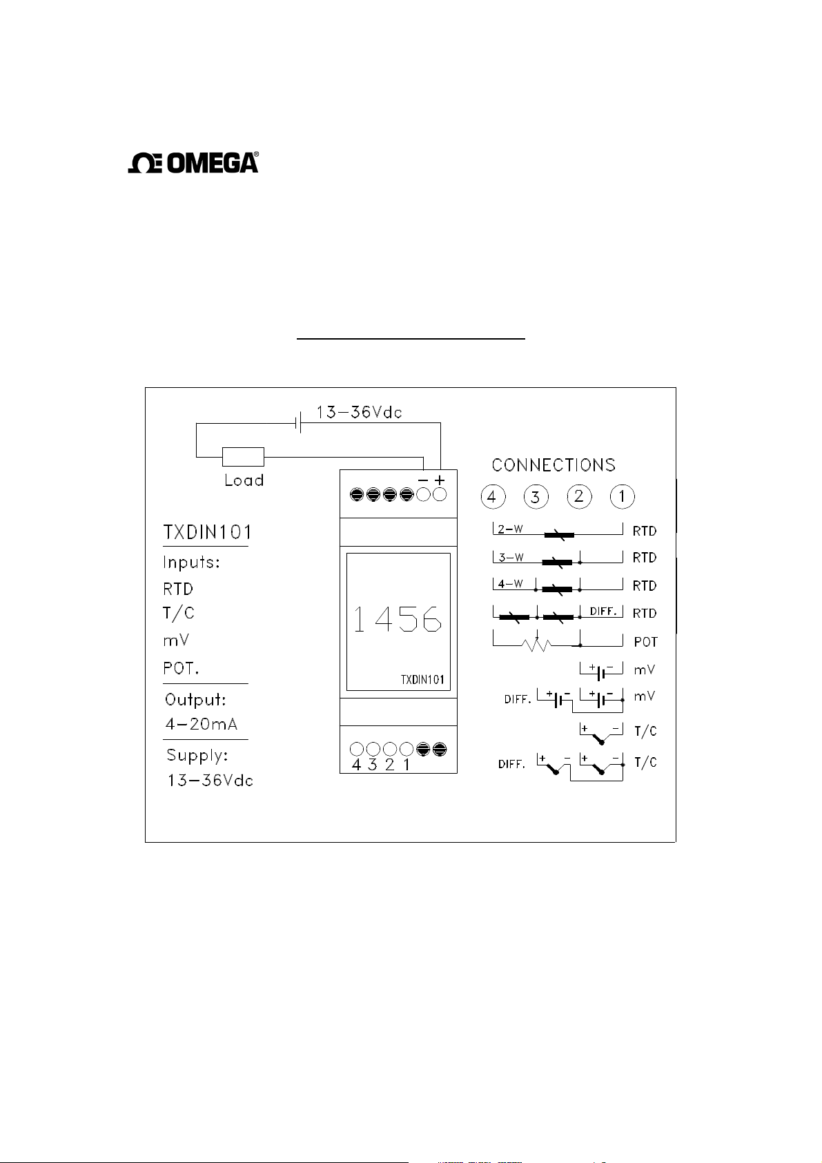
TXDIN101
CONNECTION DIAGRAM
Page 4

1. PRELUDE : ........................................................................................................................................... 4
2. ESTABLISHING THE COMMUNICATION : ............................................................................... 4
3. NEW CONFIGURATION : ............................................................................................................... 4
3.1. OPEN NEW CONFIGURATION WINDOW : .................................................................................... 5
3.2. OPEN EXISTING CONFIGURATION :............................................................................................. 5
4. STRUCTURE OF THE CONFIGURATION WINDOW : ............................................................ 6
4.1. GENERAL INFORMATION TAB :................................................................................................... 6
4.2. SENSOR TAB :.............................................................................................................................. 7
4.2.1. RTD: ............................................................................................................................... 7
4.2.2. Thermocouple: ............................................................................................................... 8
4.2.3. Voltage: .......................................................................................................................... 8
4.2.4. Potentiometer:................................................................................................................ 8
4.2.5. Resistor : ........................................................................................................................ 9
4.3. INPUT / OUTPUT RANGE TAB : ................................................................................................ 9
4.3.1. Input Range :................................................................................................................ 10
4.3.2. Output Range :............................................................................................................. 10
4.3.3. Display Range:……………………………………………………………………11
4.3.4. Burn-Out Output :........................................................................................................ 11
4.4. SET-UP TAB : ............................................................................................................................ 11
4.4.1. Mode :........................................................................................................................... 12
4.4.2. Damping Time : ........................................................................................................... 12
5. CONFIGURATION SAVE: .............................................................................................................. 12
6. UPDATING THE UNIT :…………………………………………………… ………………....12
7. CORRECTIONS : .............................................................................................................................. 15
7.1 OFFSET CORRECTION : ………………………………………………………………………..15
7.2 SLOPE CORRECTION: ……………………………………………………………………………16
8. ADDITIONAL FEATURES:………………………………..………………………………….17
8.1 RESETTING THE EXTREME MEASUREMENTS : …………… … ……………….17
8.2 PRINT :…………………… …………………………………………………………………………17
Page 5
1.
Pr
elude :
The CONCAL software provides communication with the TXDIN101 transmitter for
setting its configuration. The parameters to be configured are - sensor type,
measurement range, display reading etc.
2.
Establishing the
Communication :
The TXDIN101 communicates via USB ports.
When the unit is connected to any of the USB ports, the software automatically
searches the connected port in order to communicate thru.
In case that the selected USB port is other than the one the software remembers, it
will search the new one and it might take several seconds.
There are three ways to set the communication:
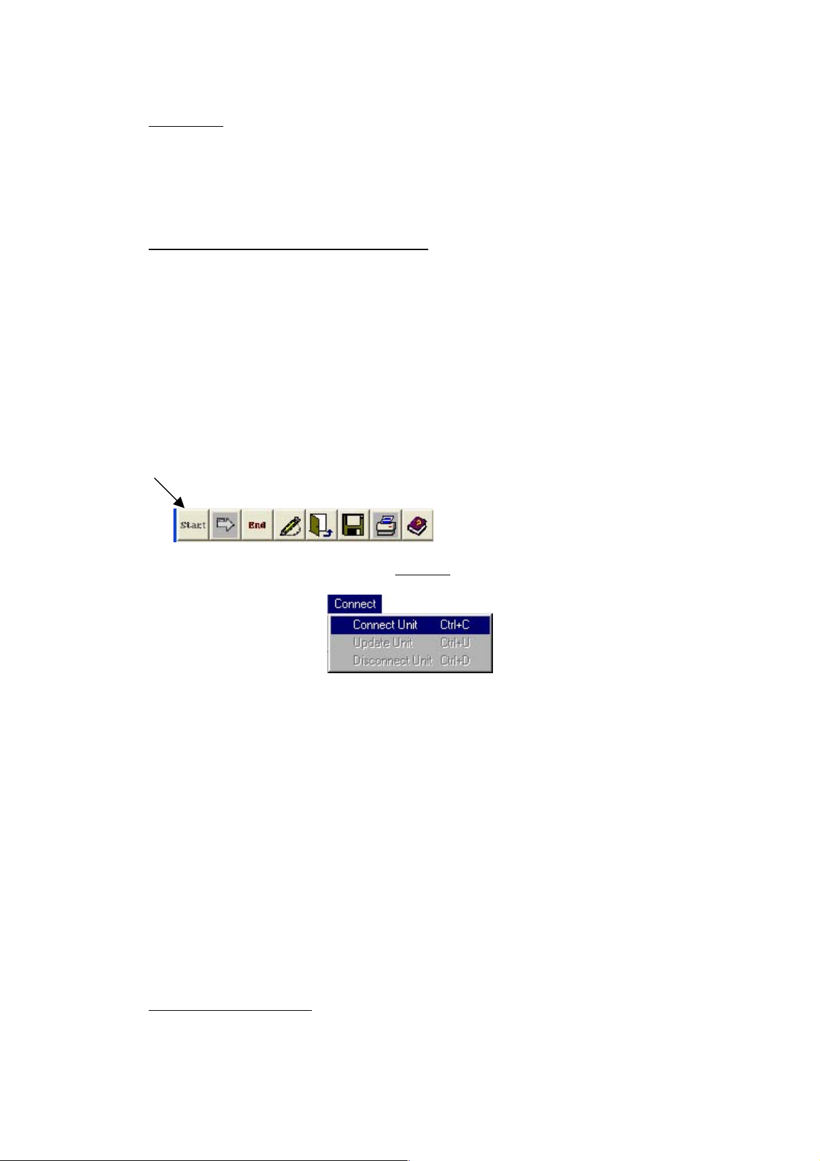
• Click the “Start” button from the Toolbar
• Select “Connect Unit” from the
Connect
on the menu line.
• Type Ctrl+C
The communication procedure consists of several steps:
1. Identification of the connected unit
2. Import of the existing configuration
3. Monitoring of the unit's current measurements
Two windows will be opened:
• "Connected Unit Configuration" - Displays the present configuration
• "Present Reading" - The measurements are displayed at 1-3
seconds rate.
3.
New Configuration:
In order to set/change the unit’s configuration, the configuration window must be
open.
Page 6
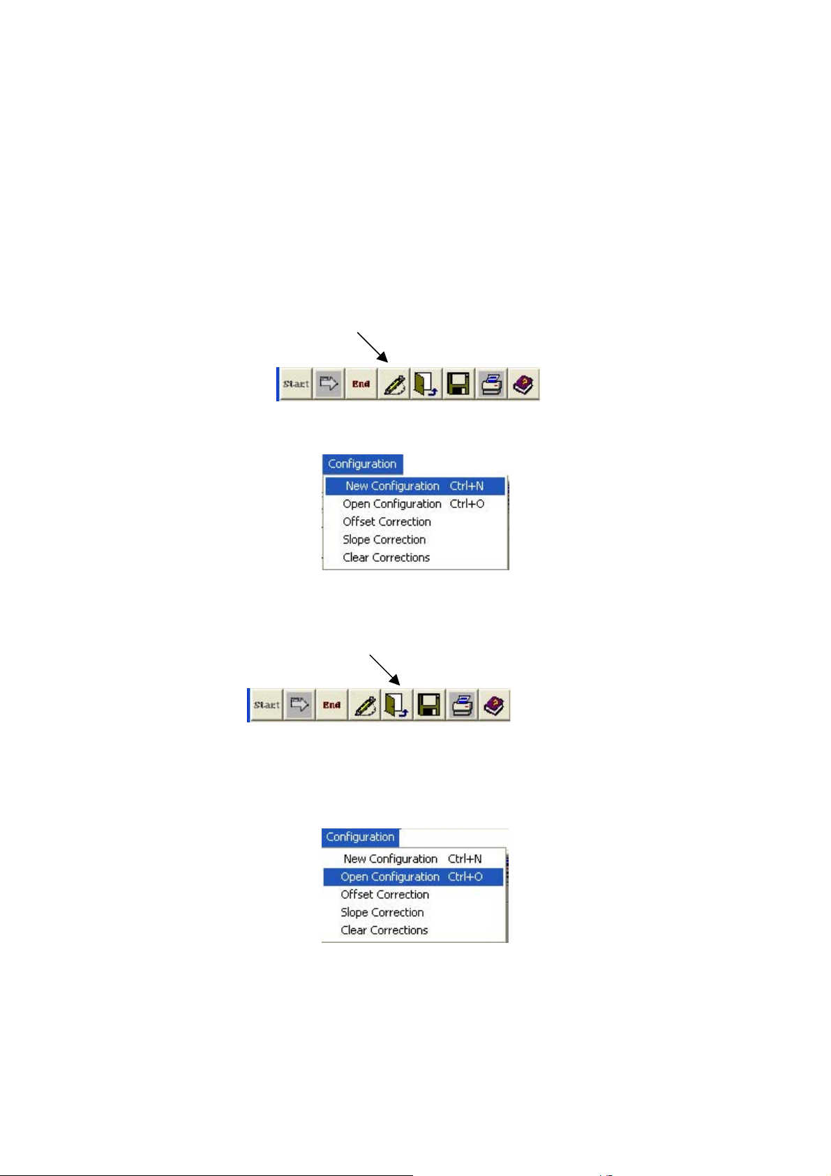
There are two ways configure the unit:
• Opening "New Configuration" window
• Opening of present configuration window
In both ways the same window is reached but the information is different.
3.1. Open "New Configuration" Window :
• The “New Configuration” button.
Or
• Select “New Configuration” option from the "Configuration" tab.
3.2 Open Existing Configuration :
Click the “Open Configuration” button.
or
• Select “Open Configuration” option from the Configuration menu.
The file containing previous configurations will appear. Double click on the required
file and the configuration box will appear containing the required configuration.
Page 7
4.
Structur
e of
The Configuration
W
indow :
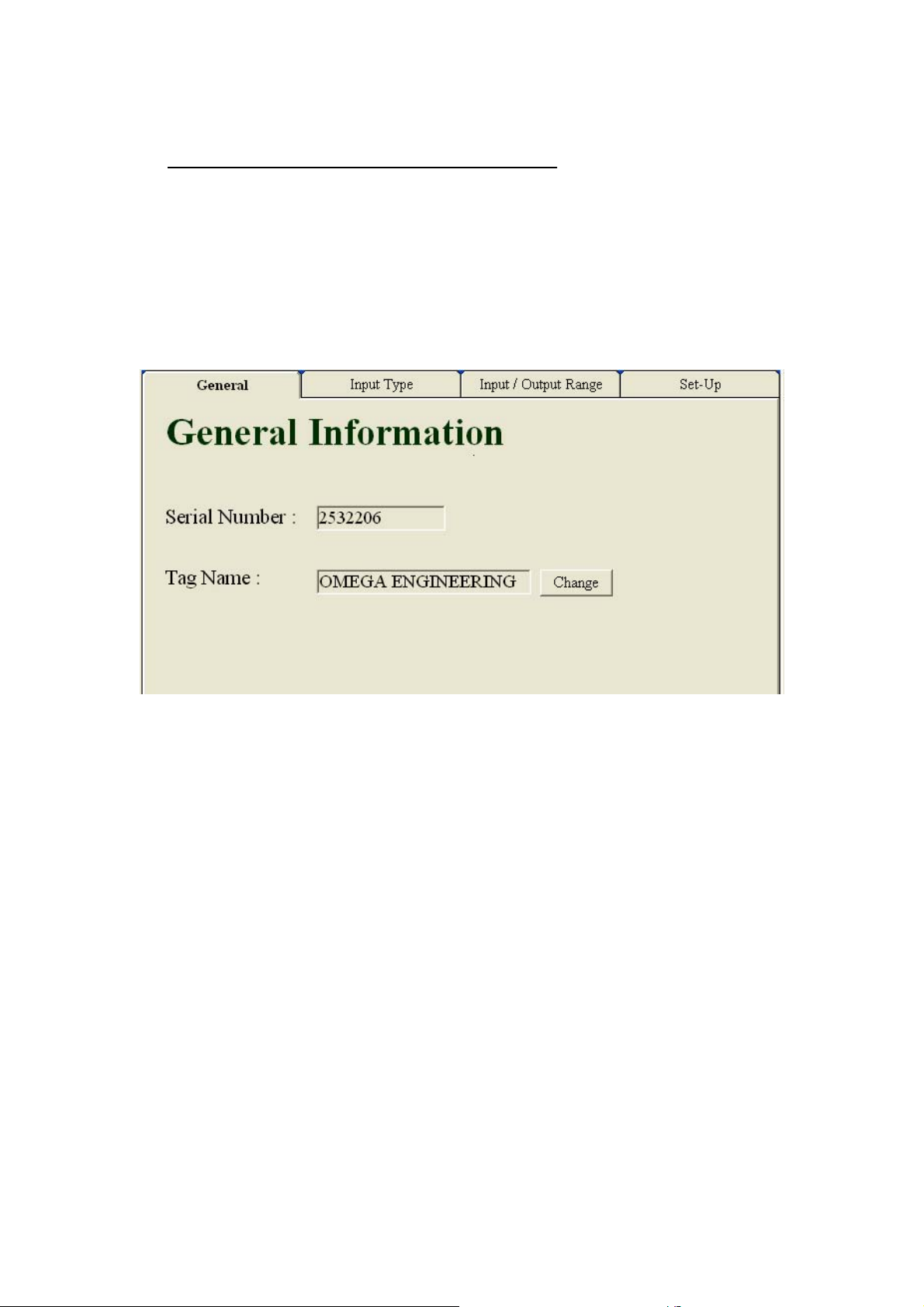
The configuration window contains four tabs:
4.1 General Information Tab
4.2 Sensor Tab
4.3 Input / Output Tab
4.4 Set-Up Tab
4.1. General Tab :
This tab is the unit's ID.
It consists of two fields:
Serial Number - The unit’s serial number, which is set by the factory and can not
be altered.
Tag Name - This field is a 19 character alphanumeric string which can be set by
the operator and be altered any time.
In order to change the contents of the tag name field, first click the
‘Change’ button.
Clicking the ‘Change’ button opens up a text field icon which the proper tag name can
be inserted.
At the end of the updating procedure, the following options are available:
Done - Saves the new contents of the field.
Cancel - Retrieves the previous configuration.
Page 8
After selecting one of the two options, the tab returns to its original form. Any
changes within the field make the field’s header to turn red helping the operator to
recognize the changes.
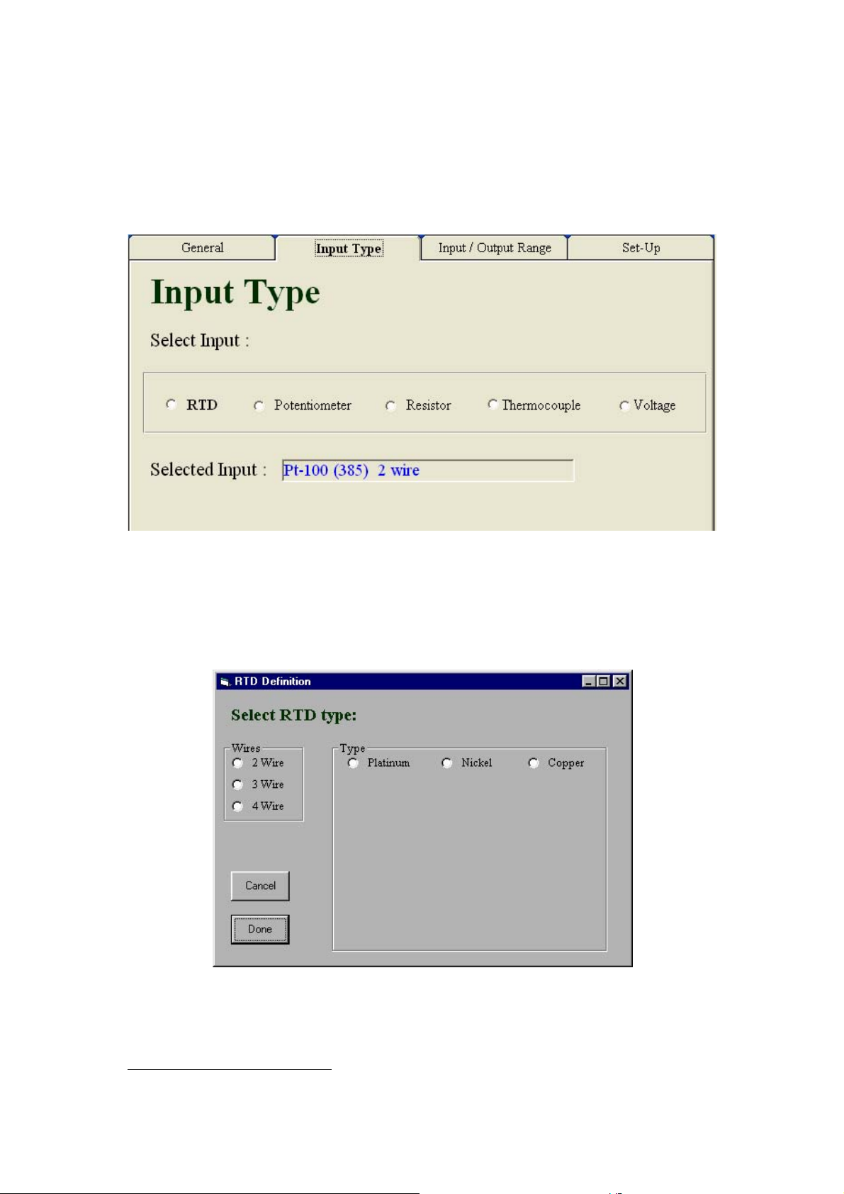
4.2. Input Tab:
The Input tab enables the operator to set the unit for the required input type.
The selected type appears in bold letters.
4.2.1. RTD:
By selecting RTD, the following window opens up :
This window provides selecting of the exact parameters of the required RTD sensor.
1
1
During the procedure other fields would open up according to the specifics of the wanted sensor.
Page 9
At the end of the updating procedure, the following options are
available:
Done - Saves the new contents of the field.
Cancel - Retrieves the previous configuration.
After selecting one of the two options, the tab returns to its original form. Any
changes within the field make the field’s header to turn red helping the operator to
recognize the changes.
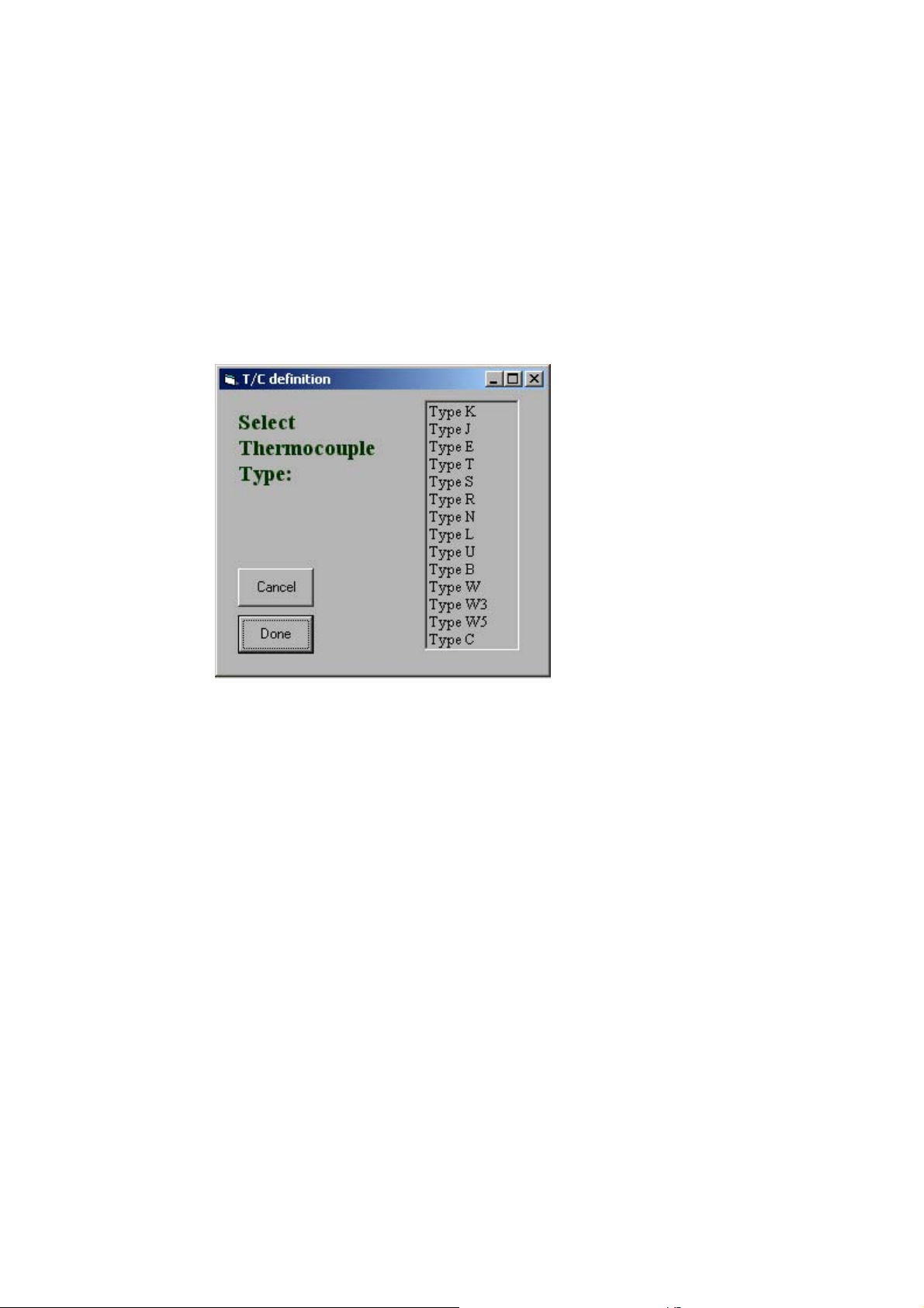
4.2.2. Thermocouple:
By selecting Thermocouple, the following window opens up :
In this window the operator can select the required thermocouple sensor from the list.
At the end of the updating procedure, the following options are
available:
Done - Saves the new contents of the field.
Cancel - Retrieves the previous configuration.
After selecting one of the two options, the tab returns to its original form. Any
changes within the field make the field’s header to turn red helping the operator to
recognize the changes.
4.2.3. Voltage:
These types of sensors do not require any further specifications.
4.2.4. Potentiometer:
By selecting the Potentiometer input, the following window opens up:
Page 10
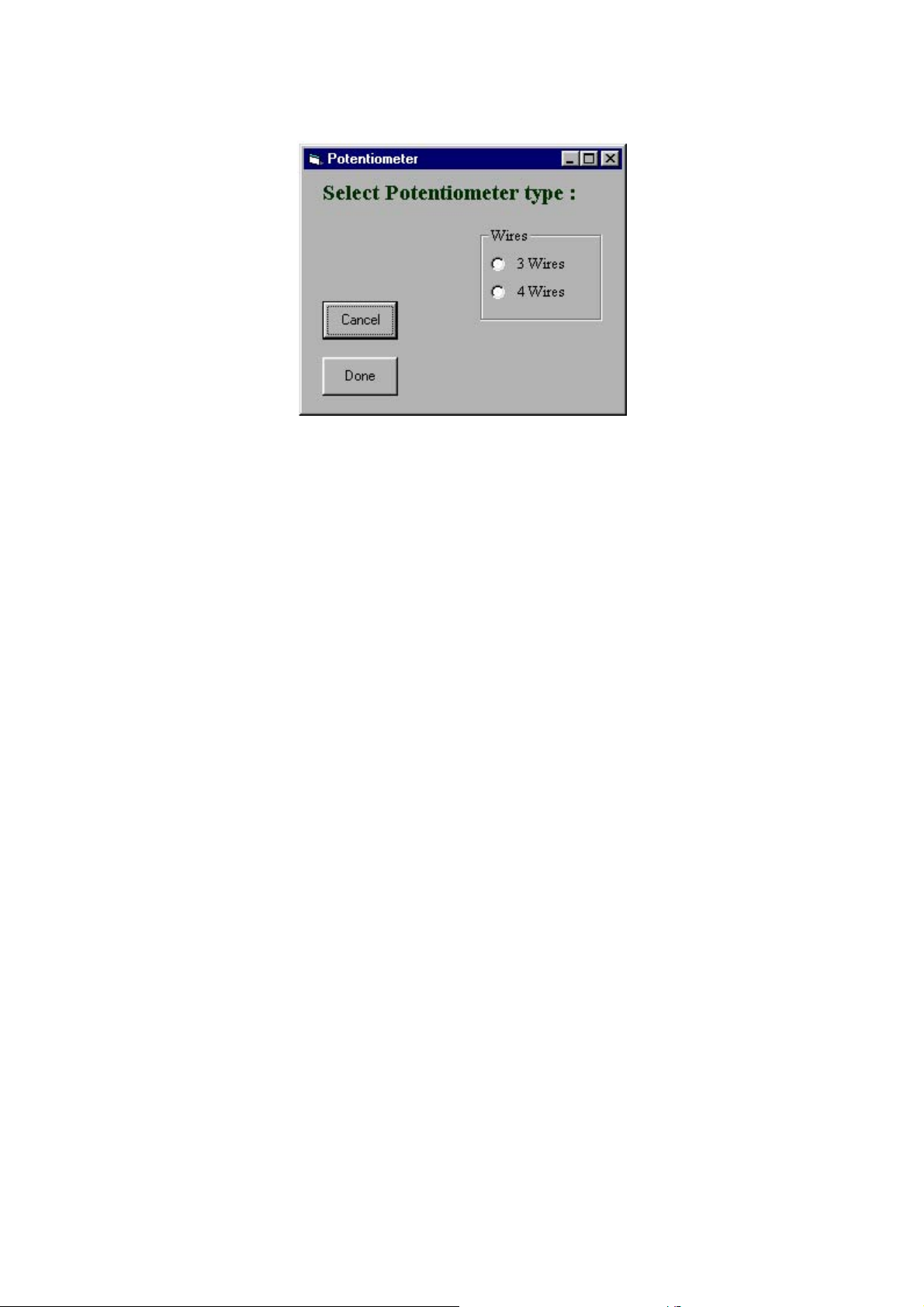
In this window the operator can select the required potentiometer connection type.
At the end of the updating procedure, the following options are
available:
Done - Saves the new contents of the field.
Cancel - Retrieves the previous configuration.
After selecting one of the two options, the tab returns to its original form. Any
changes within the field make the field’s header to turn red helping the operator to
recognize the changes.
4.2.5. Resistor:
By selecting the Resistor input, the following window opens up :
In this window the operator can select the required resistor connection type.
At the end of the updating procedure, the following options are
available:
Done - Saves the new contents of the field.
Cancel - Retrieves the previous configuration.
After selecting one of the two options, the tab returns to its original form. Any
changes within the field make the field’s header to turn red helping the operator to
recognize the changes.
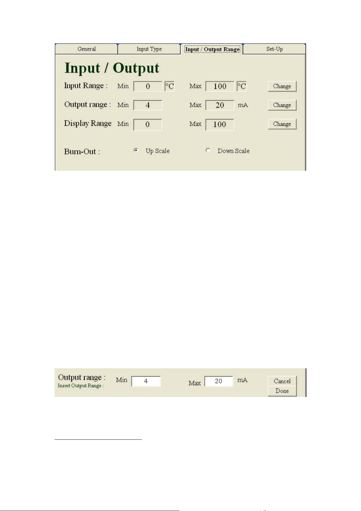
4.3 Input / Output Range Tab :
In this tab the operator can configure the input and output ranges as required.
Page 11
4.3.1. Input Range:
The input range field enables the operator to specify the measurements range for the
transmitter.
Clicking the ‘Change’ button opens up text fields for the minimum and maximum
points of the range.
2
At the end of the updating procedure, the following options are
available:
Done - Saves the new contents of the field.
Cancel - Retrieves the previous configuration.
Exceeding the maximum specified value for a specific sensor will generate
announcement and prevent setting that range.
After selecting one of the two options, the tab returns to its original form. Any
changes within the field make the field’s header to turn red helping the operator to
recognize the changes.
4.3.2. Output range:
The output range field enables setting the TXDIN101 current output.
The configuration can be any pair of values between 4 to 20 or 20 to 4 mA.
3
In order to set this field, click the ‘Change’ button.
Clicking the ‘Change’ button opens up text fields for the minimum and maximum
points of the output range.
Note: The Min or Max is to be understood as the output current at the minimum or
maximum input range points.
2
For Potentiometer type sensors, the ‘Change’ button is unavailable
since the range is constant: 0% - 100%.
3
It is possible to determine the current’s modification with an increasing value or decreasing value
(example: 4-20mA or 20-4mA).
Page 12

At the end of the updating procedure, the following options are
available:
Done - Saves the new contents of the field.
Cancel - Retrieves the previous configuration.
After selecting one of the two options, the tab returns to its original form. Any
changes within the field make the field’s header to turn red helping the operator to
recognize the changes.
4.3.3. Display Range:
This feature allows the user to determine the values to be displayed.
As a default, the Display field will be the same as the Input field.
In order to display physical units other then the input but still linear with, press the
"Change" button and insert the Minimum and the Maximum desired values to be
displayed at the minimum and the maximum input points.
At the end of the updating procedure, the following options are
available:
Done - Saves the new contents of the field.
Cancel - Retrieves the previous configuration.
After selecting one of the two options, the tab returns to its original form. Any
changes within the field make the field’s header to turn red helping the operator to
recognize the changes.
4.3.4. Burn-Out Output:
The burn-out field enables to define which value would be output by the transmitter in
case of mal function with the sensor..
Up Scale - Output current grater than 20mA.
Down Scale - Output current lower that 4mA.
At the end of the updating procedure, the following options are
available:
Done - Saves the new contents of the field.
Cancel - Retrieves the previous configuration.
After selecting one of the two options, the tab returns to its original form. Any
changes within the field make the field’s header to turn red helping the operator to
recognize the changes.
4.4 Set-Up Tab:
Page 13
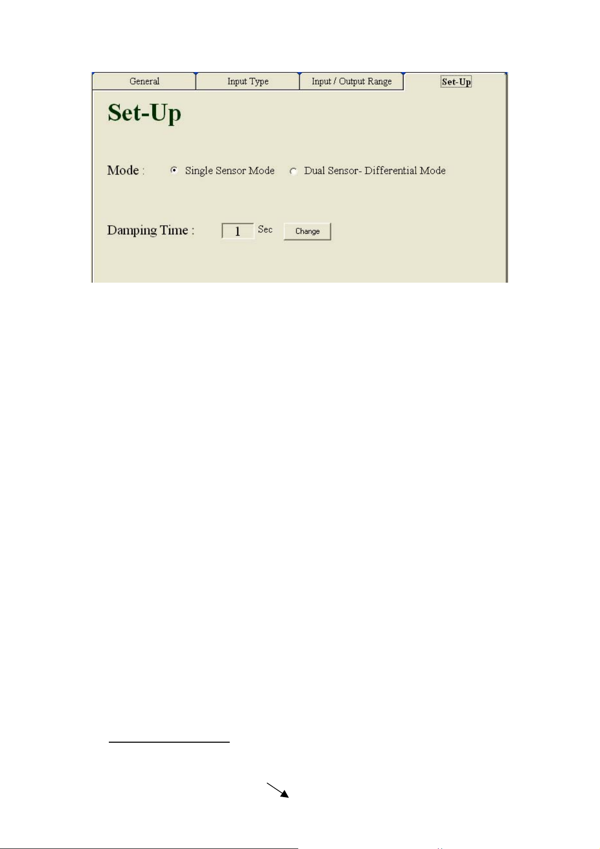
In this tab the operator can define a few general configurations.
The setting contains the following fields:
4.4.1 Mode:
The Mode option provides selecting of single or dual sensor (in differential mode)
input.
Single Mode- One sensor is connected.
Dual Sensor – Differential Mode – Two sensors are connected. The transmitter
outputs the difference between them.
4.4.2 Damping Time:
The damping time field provides integration time in seconds.
In order to update this field, click the ‘Change’ button.
Clicking the ‘Change’ button opens up text fields for the period on which the
moderation would be.
There are 2 possible ranges in this field:
No Damping Time - By selecting the value 0 no integration will take place.
Damping Time - By selecting value 1-100 the operator sets the integration period
At the end of the updating procedure, the following options are
available:
Done - Saves the new contents of the field.
Cancel - Retrieves the previous configuration.
After selecting one of the two options, the tab returns to its original form. Any
changes within the field make the field’s header to turn red helping the operator to
recognize the changes.
5.
Configuration Save:
The configuration save procedure can be accomplished by ether of the 2 following
Page 14
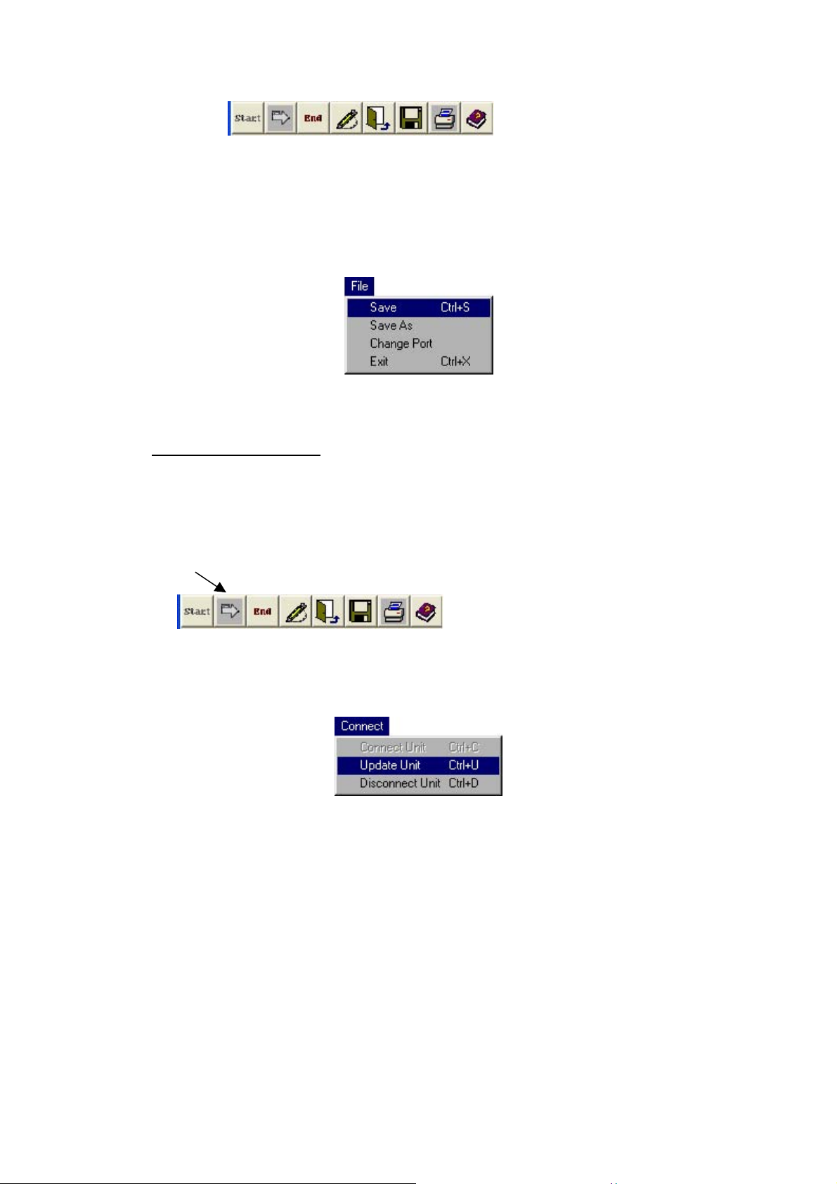
methods:
• The “Save” button.
or
• Select “Save” option from the File menu.
The file should be saved in a dedicated folder.
6.
Updating
The
Unit :
When the setting phase is completed, the TXDIN101 should be updated.
The updating procedure can be accomplished by ether of the two following methods:
• The “Update Unit” button.
Or
• Select “Update Unit” option from the Connect menu.
Page 15
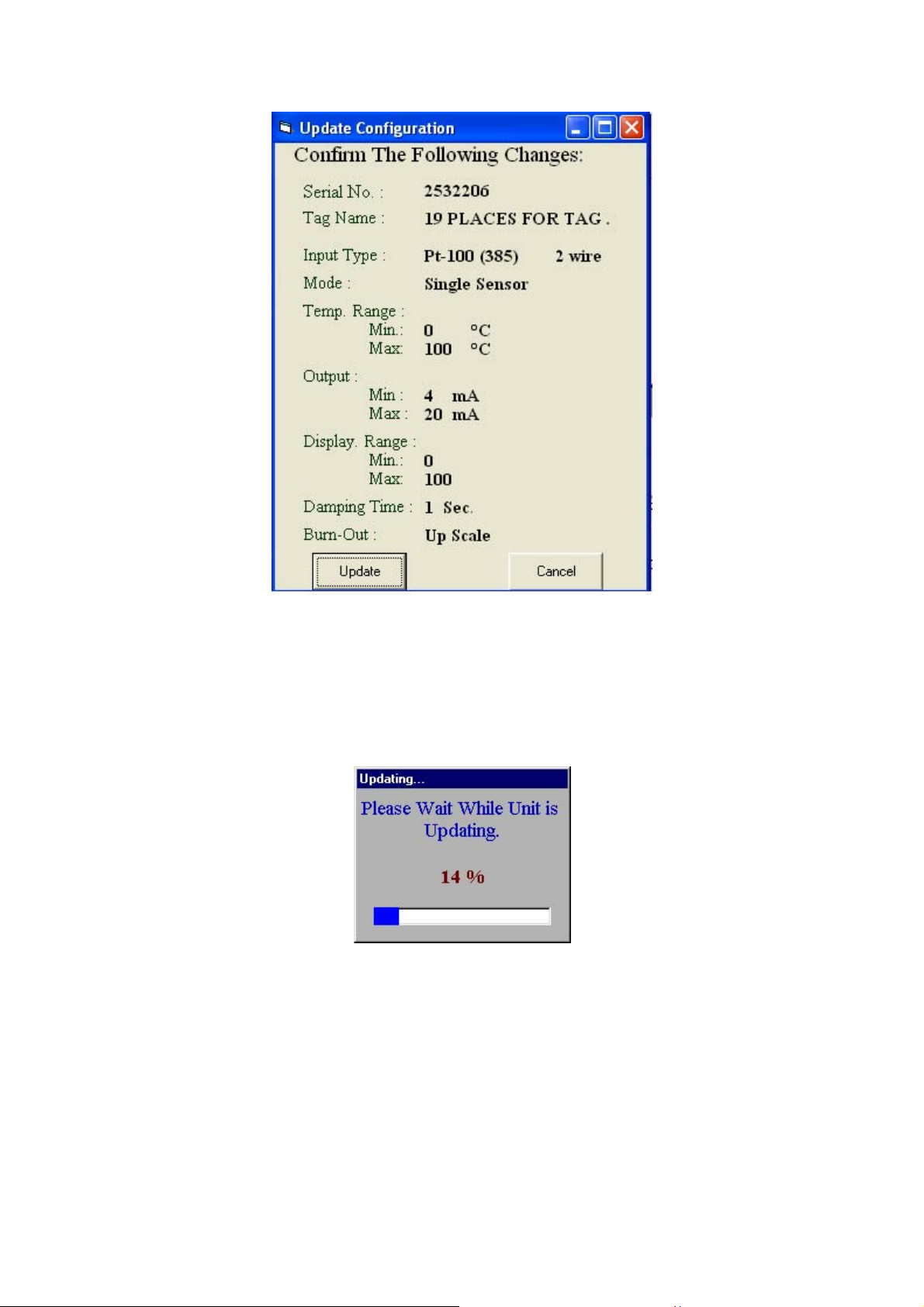
Click the “Update” button to proceed with the updating procedure.
“Updating…” window appears indicating the process progress.
.
Page 16
7.
Corr
ections:
This feature allows the operator to change the factory calibration.
This function is useful to set a probe-transmitter calibrated pair or set a matched
balance between several measuring points.
There are two types of user changes:
• Offset correction
• Slope correction
7.1 Offset Corrections
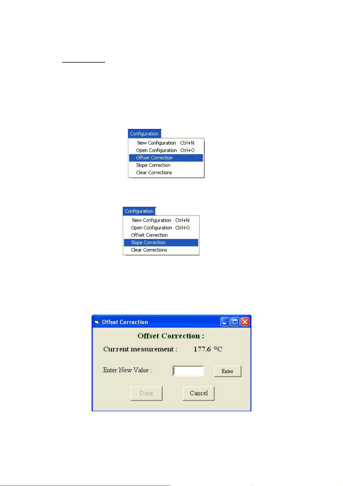
For cases when the TXDIN101 output differs by a fix (offset) error throughout the
entire span, select the “Offset Correction” option from the "Configuration" menu:
The accurate value should be entered.
Page 17
At the end of the updating procedure, the following options are
available:
Done - Saves the new contents of the field.
Cancel - Retrieves the previous configuration.
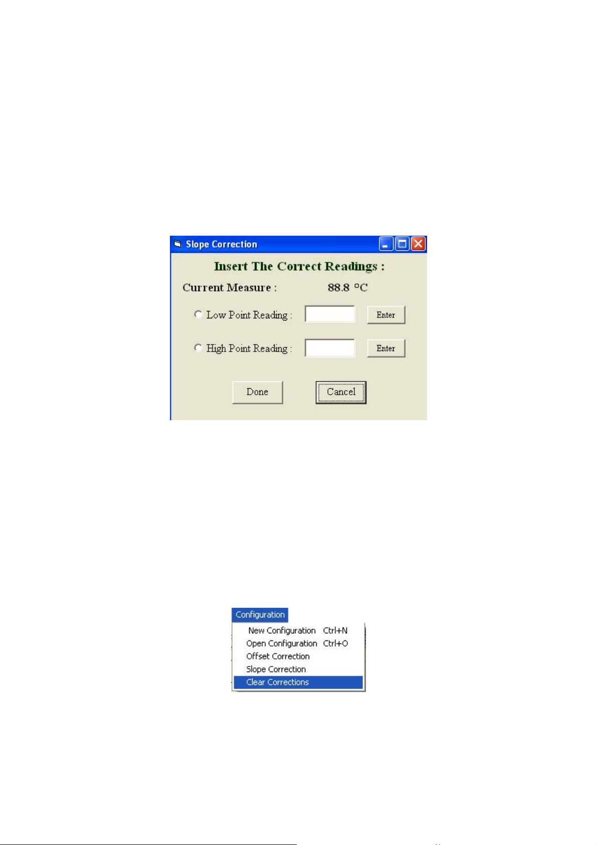
7.2 Slope Correction
For cases when the TXDIN101 should match a different sensor behavior than the
standard sensor's table, select the “Slope Correction” option from the "Configuration"
menu:
First set the input to the low point measurement, and then enter the desired reading –
press "Enter". Then set the input to the high point measurement, and then enter the
desired reading – press "Enter"
At the end of the updating procedure, the following options are available:
Done - Saves the new contents of the field.
Cancel - Retrieves the previous configuration.
Clear Corrections:
In order to erase all the corrections and bring the TXDIN101 to its original
calibration select the “Clear Corrections” from the "Configuration" menu.
Page 18
The “Updating…” window appears on the screen. (The same as the one appears
during the updating process).
4
8. Additional Features :
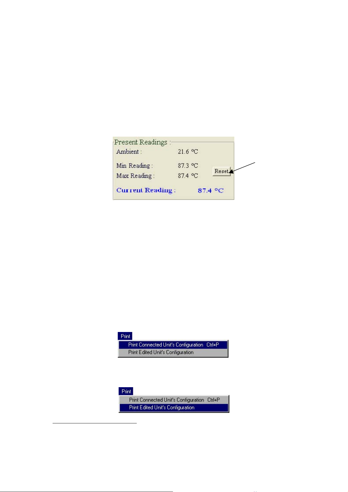
8.1 Resetting The Extreme Measurements :
The Min and Max Readings display the process extreme measurements. This function
is operational only when the unit is not connected to the PC.
Pressing the "Reset" button, clears the reading.
The “Updating…” window appears on the screen.
At the end of the resetting process, the “Min Reading” and “Max Reading” fields
contains extreme readout of -20000 and +20000.
8.2 Print
The system provides the operator to keep an hardcopy archive containing the different
configurations defined by the operator.
There are 2 different types of printing:
• Print Connected Unit’s Configuration - Prints the configuration of
the connected unit.
• Print Edited Unit’s Configuration - Prints the contains of the
Configuration window.
4
Note that this feature starts automatically if the operator tries to correct sensors’ error, when there is
already other previous configuration of sensors’ error.
On any case, before the process starts the system let the operator decide whether to continue or to stay
with the present configuration.
Page 19
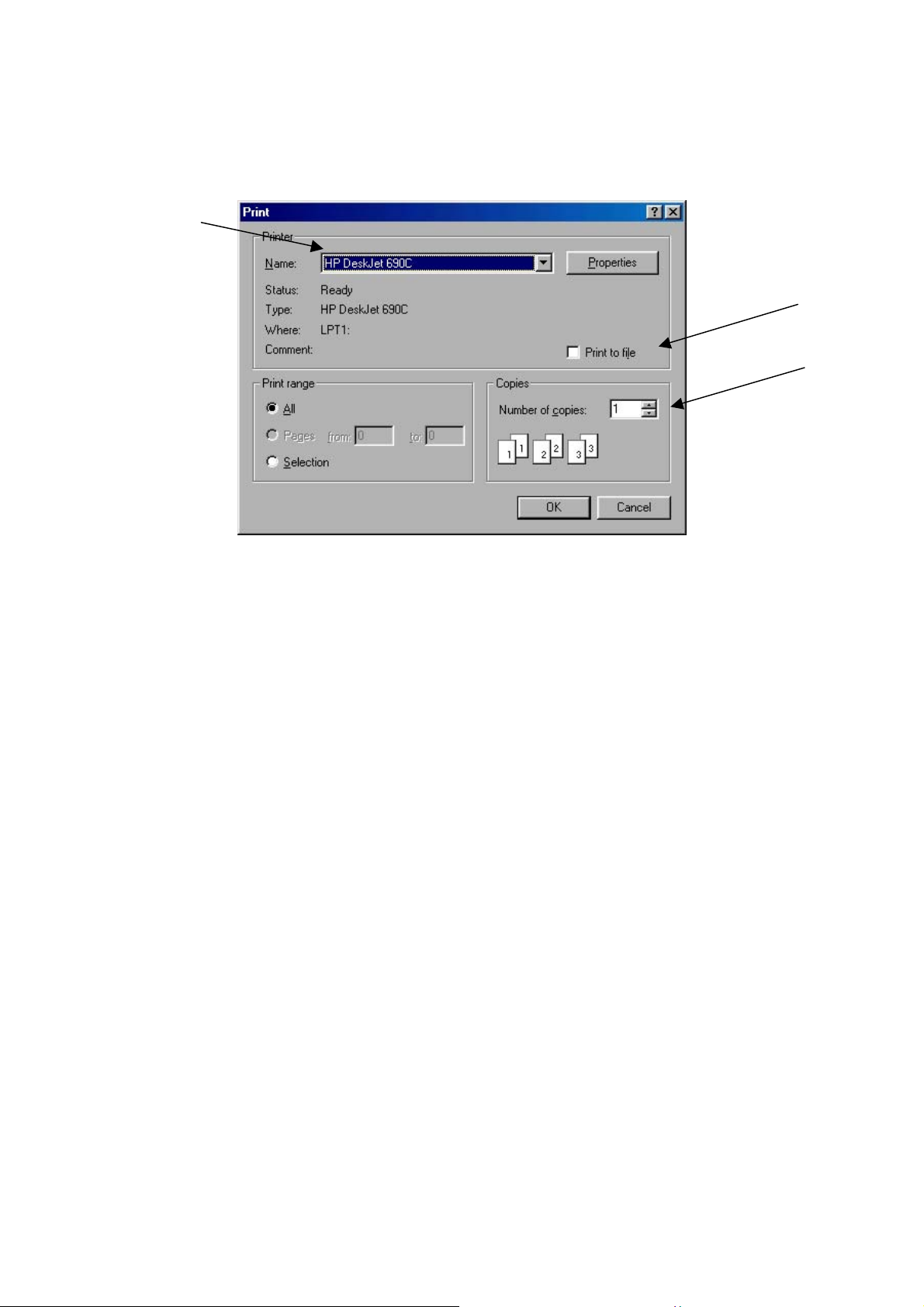
Commencing 1 of the 2 options would open a standard windows printing window :
In this window the operator can define a few options:
Selecting the printer that will print the configuration.
Selecting between printing on paper or directly to a file.
Defining how many copies to print.
At the end of the updating procedure, the following options are
available:
Done - Saves the new contents of the field.
Cancel - Retrieves the previous configuration.
Page 20
Page 21

 Loading...