

Page 1
TX92
RTD Temperature Transmitter
FM
APPROVED
omega.com
e-mail: [email protected]
For latest product manuals:
omegamanual.info
User’s Guide
Shop online at
Page 2

Servicing
North America:
U.S.A.:
ISO 9001 Certified
OMEGA Engineering, Inc., One Omega Drive,
P.O. Box 4047, Stamford, CT 06907-0047 USA
Toll-Free: 1-800-826-6342 TEL: (203) 359-1660
FAX: (203) 359-7700 e-mail: [email protected]
Canada:
976 Bergar
Laval (Quebec), H7L 5A1 Canada
Toll-Free: 1-800-826-6342 TEL: (514) 856-6928
FAX: (514) 856-6886 e-mail: [email protected]
For immediate technical or
application assistance:
U.S.A. and Canada:
Sales Service: 1-800-826-6342/1-800-TC-OMEGA
®
Customer Service: 1-800-622-2378/1-800-622-BEST
®
Engineering Service: 1-800-872-9436/1-800-USA-WHEN
®
Mexico/Latin America:
En Español: 001 (203) 359-7803
FAX: 001 (203) 359-7807
e-mail: [email protected]
OMEGAnet®On-Line Service Internet e-mail
omega.com [email protected]
Page 3

It is the policy of OMEGA Engineering, Inc. to comply with all worldwide safety and EMC/EMI regulations that apply. OMEGA is constantly pursuing certification of its products to the European New Approach Directives. OMEGA will add the CE mark to every appropriate device upon
certification.
The information contained in this document is believed to be correct, but OMEGA accepts no liability for any errors it contains,
and reserves the right to alter specifications without notice.
WARNING: These products are not designed for use in, and should not be used for, human
Benelux:
Managed by the United Kingdom Office
Toll-Free: 0800 099 3344 TEL: +31 20 347 21 21
FAX: +31 20 643 46 43 e-mail: [email protected]
Czech Republic:
Frystatska 184, 733 01 Karviná, Czech Republic
Toll-Free: 0800-1-66342 TEL: +420-59-6311899
FAX: +420-59-6311114
e-mail: [email protected]
OMEGA’s policy is to make running changes, not model changes, whenever an improvement is possible. This affords our customers
the latest in technology and engineering.OMEGA is a registered trademark of OMEGA ENGINEERING, INC.
© Copyright 2011 OMEGA ENGINEERING, INC. All rights reserved. This document may not be copied, photocopied, reproduced,
translated, or reduced to any electronic medium or machine-readable form, in whole or in part, without the prior written consent of
OMEGA ENGINEERING, INC.
RETURN REQUESTS / INQUIRIES
Direct all warranty and repair requests/inquiries to the OMEGA Customer Service Department. BEFORE RETURNING ANY
PRODUCT(S) TO OMEGA, PURCHASER MUST OBTAIN AN AUTHORIZED RETURN (AR) NUMBER FROM OMEGA’S CUSTOMER
SERVICE DEPARTMENT (IN ORDER TO AVOID PROCESSING DELAYS). The assigned AR number should then be marked on the
outside of the return package and on any correspondence. The purchaser is responsible for shipping charges, freight, insurance
and proper packaging to prevent breakage in transit.
Servicing Europe:
FOR WARRANTY RETURNS, please have the following
information available BEFORE contacting OMEGA:
1.Purchase Order number under which the product was
PURCHASED,
2. Model and serial number of the product under warranty, and
3.Repair instructions and/or specific problems relative to the
product.
FOR NON-WARRANTY REPAIRS,
consult OMEGA
for current repair charges. Have the following
information available BEFORE contacting OMEGA:
1. Purchase Order number to cover the COST of the repair,
2. Model and serial number of the product, and
3.Repair instructions and/or specific problems relative to the
product.
France:
Managed by the United Kingdom Office
Toll-Free: 0800 466 342 TEL: +33 (0) 161 37 29 00
FAX: +33 (0) 130 57 54 27 e-mail: [email protected]
Germany/Austria:
Daimlerstrasse 26
D-75392 Deckenpfronn, Germany
Toll-Free: 0800 6397678 TEL: +49 (0) 7056 9398-0
FAX: +49 (0) 7056 9398-29 e-mail: [email protected]
United Kingdom: ISO 9001 Certified
OMEGA Engineering Ltd.
One Omega Drive, River Bend Technology
Centre, Northbank, Irlam, Manchester
M44 5BD United Kingdom
Toll-Free: 0800-488-488
TEL: +44 (0) 161 777-6611
FAX: +44 (0) 161 777-6622
e-mail: [email protected]
Page 4

TX92
Miniature Two-Wire RTD Transmitter
Page
Section 1 Introduction 1
1.1 General Description . . . . . . . . . . . . . . . . . . . . . . . . . . . . . . . . . . . 1
1.2 Features . . . . . . . . . . . . . . . . . . . . . . . . . . . . . . . . . . . . . . . . . . . . . . 5
1.3 Models Available . . . . . . . . . . . . . . . . . . . . . . . . . . . . . . . . . . . . . . 5
Section 2 Unpacking Instructions 6
Section 3 Installation 8
3.1 Mounting the TX92 . . . . . . . . . . . . . . . . . . . . . . . . . . . . . . . . . . . . 8
3.2 Wiring the TX92 . . . . . . . . . . . . . . . . . . . . . . . . . . . . . . . . . . . . . . . 13
TABLE OF
CONTENTS
i
Page 5

TX92
Miniature Two-Wire RTD Transmitter
Page
Section 4 Calibration Instructions 15
4.1 Equipment Required . . . . . . . . . . . . . . . . . . . . . . . . . . . . . . . . . . . 15
4.2 Calibration Procedures . . . . . . . . . . . . . . . . . . . . . . . . . . . . . . . . 16
Section 5 Troubleshooting Guide 20
Section 6 Accessories 22
Section 7 Specifications 23
Appendix A
Intrinsically Safe Interconnection Diagram . . . . . . . . . . . . . . . . . . . . . 25
TABLE OF
CONTENTS
ii
Page 6

1
1
Introduction
1.1 General Description
The Omega®TX90 Series Temperature Transmitters consist of the
TX91 Miniature Two-Wire Thermocouple Transmitter and the TX92
Miniature Two-Wire RTD Transmitter. This manual is written for the
TX92 RTD Transmitter.
The TX92 Two-Wire RTD Transmitter will produce a standard
4-20 mA output signal proportional to that produced by its RTD
input temperature sensor. Transmission of the proportional current
output may be accomplished by using copper wires. The TX92
RTD Transmitter accepts 100 Ohm, Platinum RTD sensors (PT100,
alpha=0.00385).
Page 7
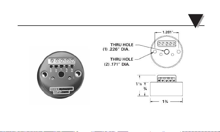
Figure 1-1. Photo of TX90 Series Transmitter
Figure 1-2. General Dimensions (in inches)
12
Introduction 1
(For Mounting)
Page 8
3
1 Introduction
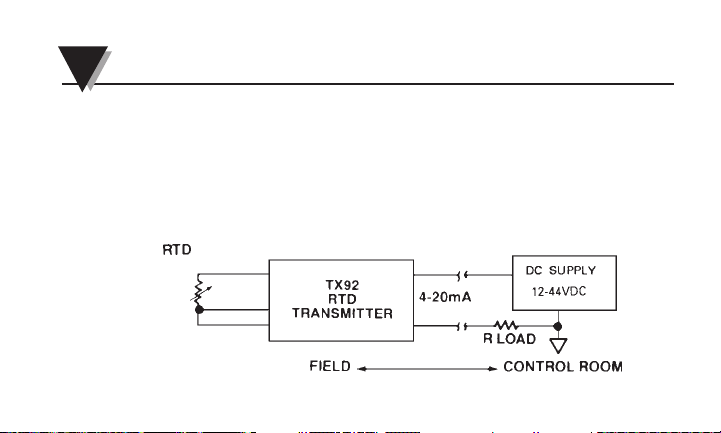
The TX92 transmitter is normally powered by an unregulated DC
power supply as shown in Figure 1-3. The proportionally-transmitted
signal begins at 4 mA, at the low end of its temperature range, and
increases to 20 mA, at the high end of its temperature range. (There
are various temperature ranges available for the TX92 transmitter. To
order, refer to Section 1.3 Table 1.1 for correct Model Numbers and
Range Codes.)
Figure 1-3. TX92 RTD Transmitter
Input
Output
Page 9

04
Introduction 1
The TX92 two-wire transmitter will work with 2-wire or 3-wire RTDs
and provides an output current of 4-20 mA proportional to the RTD
sensor. When the transmitter is mounted inside a protection head
(such as the OMEGA NB1 Protection Head) two copper wires now
carry the temperature signal and DC voltage to operate the
transmitter, thereby reducing possible noise pick-up errors. The TX92
does NOT provide isolation between its input and the 4-20 mA
output. Note, however, that the RTD element is electrically insulated.
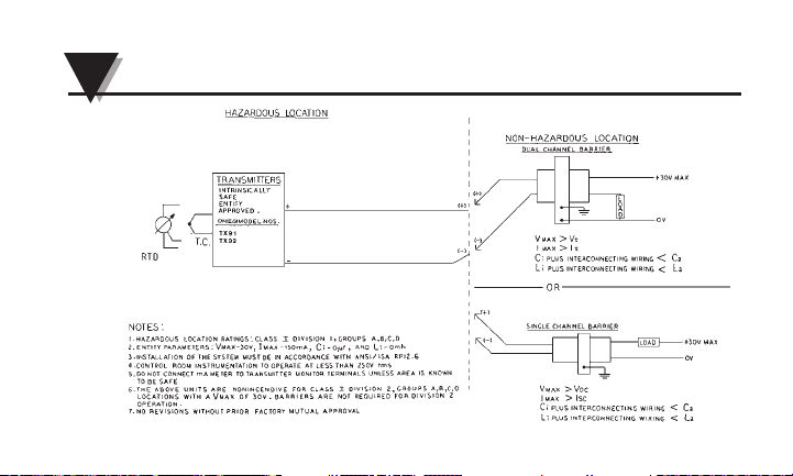
The TX92 is FM Approved when wired with the proper intrinsic
safety barriers. (See Intrinsically Safe Interconnection Diagram –
Appendix A.)
Page 10

Model Number Description
TX92-(*) RTD transmitter (100Ω, Pt, alpha = 0.00385)
PRTX-(*) PR-12 RTD probe, 12" L,
1
/4" O.D.,
304SS sheath
TX92 Models Available
1.2 Features
• 4-20 mA output
• ±0.1% full-scale accuracy
(with the respect to the RTD input resistance)
• Upscale break protection
• Low cost
1.3 Models Available
1 Introduction
5
Page 11

Table 1-1. Range Code
Input Types
Range RTD Range RTD
-40 to 1120˚F 1 -40 to 1500˚F 4
-40 to 1200˚F 2 -40 to 1750˚F 5
-40 to 1300˚F 3 -40 to 1000˚F 6
16
Introduction 1
*Insert range code from Table 1-1
For complete information on PR-12 RTD Probes, see the OMEGA
Temperature Handbook.
Page 12
7
2
Unpacking
Remove the packing list and verify that all equipment has been
received. If there are any questions about the shipment, please call
the OMEGA Customer Service Department.
Upon receipt of shipment, inspect the container and equipment for
signs of damage. Take particular note of any evidence of rough handling in transit. Immediately report any damage to the shipping
agent.
NOTE
The carrier will not honor any claims unless all shipping material
is saved for their examination. After examining and removing contents,
save packing material in event reshipment is necessary.
Page 13

3.1 Mounting the TX92
The TX92 Transmitter may be:
1. surface mounted,
2. mounted inside a protection head (refer to figure 3-1), or
3. installed into the OMEGA mounting track (part number RT) using an
OMEGA mounting bracket (part number TX90-BR).
Figure 3-2 shows the RT mounting track.
Figure 3-3 shows the TX90-BR mounting bracket.
Figure 3-4 shows a typical installation of two transmitters using the
bracket and mounting track.
08
3
Installation
Page 14
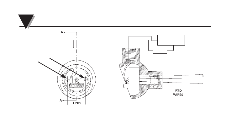
3 Installation
Figure 3-1 Assembly of the TX92 RTD Transmitter Inside
an OMEGA NB1 Protection Head (in inches)
9
DC SUPPLY
12-44VDC
LOAD
MOUNTING
HOLES
Page 15
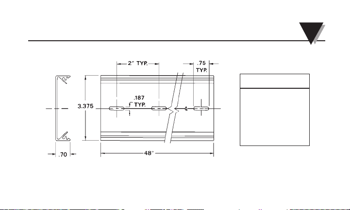
Figure 3-2 RT Mounting Track (in inches)
10
Installation 3
CAUTION
HANDTIGHTEN
TRANSMITTER
MOUNTING
SCREWS ONLY.
DO NOT OVERTIGHTEN.
Page 16
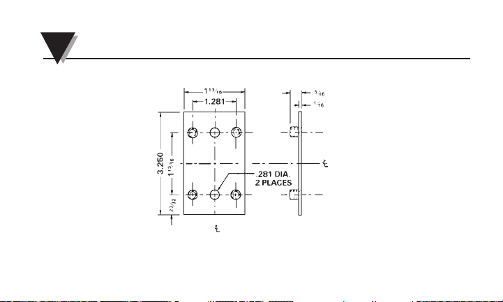
3 Installation
11
Figure 3-3 TX90-BR Mounting Bracket (in inches)
Page 17
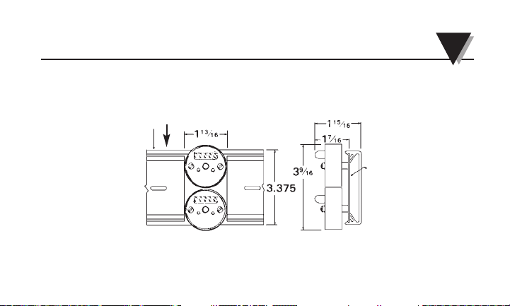
Figure 3-4 Installation with Bracket and Track (in inches)
12
Installation 3
MOUNTING TRACK (RT)
MOUNTING
BRACKET
TX90-BR
Page 18
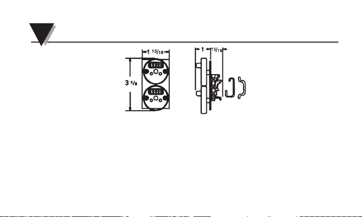
Figure 3-5 TX90-DIN DIN Rail Mounting Adapter (in inches)
3 Installation
13
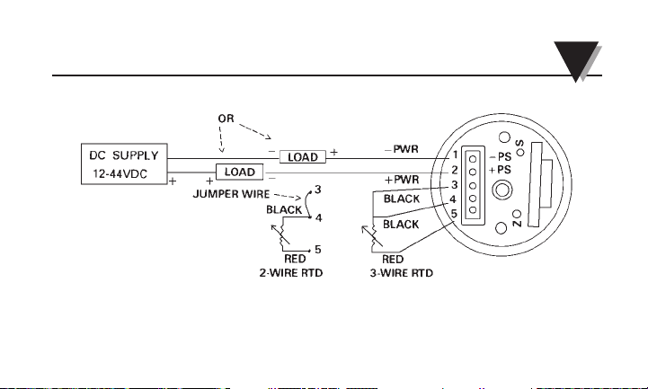
3.2 Wiring the TX92 (Refer to Figure 3-5)
1. Connect a DC power supply in series with the load to the
(+PS) and (-PS) power terminals. Note that the load (usually
a monitoring instrument) may be connected to either the
(+) or (-) power lead.
2. Connect the RTD element to the input terminals as shown.
Page 19
Installation 3
Figure 3-6 Wiring Diagram for the TX92
14
Page 20

15
4
Calibration Instructions
4.1 Equipment Required
• Precision Decade Resistance Box, with 0.01 ohm resolution and
Ⳳ0.02 ohm accuracy or
• Precision RTD Simulator, such as the OMEGA Model CL511
Precision Calibrator
• Precision DMM capable of measuring mA, with 0.001 mA
resolution and Ⳳ0.002 mA accuracy
• Or a Thermocouple/RTD Calibrator/Simulator
Page 21

16
Calibration Instructions 4
4.2 Calibration Procedures (Refer to Figure 4-1)
Connect the calibration equipment according to Figure 4-1.
Standard copper test leads are used with RTD instrumentation.
To check or adjust the calibration:
1. Locate the Z (zero) and S (span) potentiometers.
2. Select, from Table 4-1, the correct ohmic values for the Z (zero)
and S (span) adjustments that correspond to the Model
Number. For example, for Model TX92-2, the Z value is 93.04
ohms, and the S value is 135.97 ohms.
Page 22

17
4 Calibration Instructions
If a Thermocouple/RTD Simulator is used, such as the OMEGA
Model CL511 Precision Calibrator, select the Temperature Input Z
(zero) and S (span) values.
3. Set the decade box to the selected Z (zero) ohmic value. Adjust the
Z potentiometer to read 4.000 mA on the monitoring instrument.
4. Set the decade box to the selected S (span) ohmic value. Adjust the
S potentiometer to read 20.000 mA on the monitoring instrument.
5. Repeat steps 3 and 4, as required, until the readings are exactly
4.000 mA and 20.000 mA. This procedure is necessary since there
is interaction between the two potentiometers.
Page 23
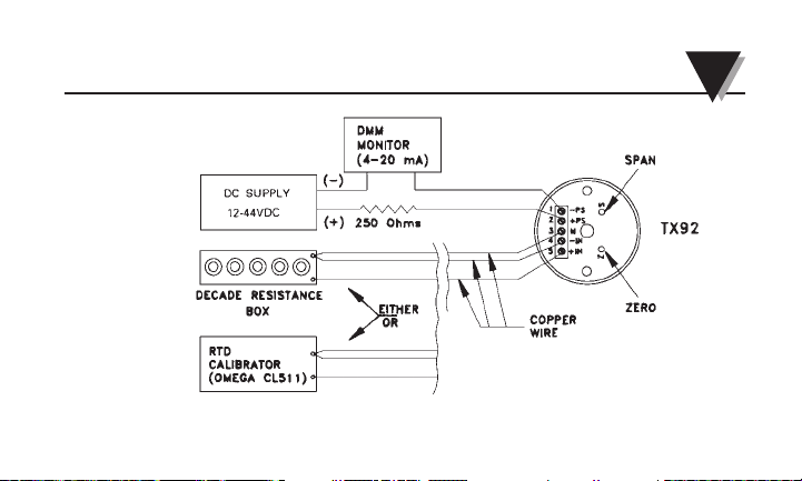
Figure 4-1. TX92 RTD Calibration Set-Up.
18
Calibration Instructions 4
Page 24

4 Calibration Instructions
19
Table 4-1. Calibration Values for the TX92
Temperature Resistance Input (Ohms)
Input Range Model Alpha = 0.00385
Zero/Span TX92 Zero/Span
-40/120˚F -1 84.27/118.97
0/200˚F -2 93.04/135.97
0/300˚F -3 93.04/156.90
0/500˚F -4 93.04/197.69
0/750˚F -5 93.04/246.65
0/1000˚F -6 93.04/293.39
Page 25

Malfunction or incorrect operation may be caused by:
1. Incorrect Readings:
Check for improper wiring (Refer to Figure 3-5.)
2. Loose or broken wires:
Check each terminal connection for tightness. Move each wire
back and forth and note any changes in operation.
3. Too high a load resistance in the output current loop or too low
a current rating on the power supply:
20
5
Troubleshooting Guide
Page 26

21
5 Troubleshooting Guide
a) Measure the total resistance of each device (excluding the
transmitter and power supply) in the 20 mA loop, including the
resistance of the lead wires.
b) Calculate the maximum allowable loop resistance using the
formula:
Loop Resistance (maximum) = V
supply
-12V
0.020A
For example, a 24V power supply would give a maximum loop
resistance of: 12V/0.020A = 600 ohms.
c) Make sure the power supply is rated for at least 28 mA times the
number of TX92 transmitters being powered. For example, if the
supply is powering 5 transmitters, the supply should be rated for
at least 140 mA.
Page 27

22
6
Accessories
Model No. Description
TX90-BR Mounting Bracket
PSU-24B Unregulated Power Supply, 24 Volts
TX82B Process Loop-Powered Indicator
RT 48” Mounting Track
TX90-DIN DIN Rail Mounting Adapter
RAIL-35-2 6.5 Section 35mm DIN Rail
Page 28

23
7
Specifications
General
Size: 1.75" dia. X 1.125" high (includes terminal strip)
Zero/Span Adjustment
Range: ±25%
Power Supply Voltage
Operating Range: +12VDC to +44VDC, 28 mA max required per
transmitter
Accuracy: ±0.1% of full scale (includes effects of hysteresis,
repeatability and linearity proportional to the RTD input)
Ambient Temperature: -13˚F to 185˚F (-25˚C to 85˚C)
Storage Temperature
Range: -85˚F to 193˚F (-65˚C to 89˚C)
Page 29

Specifications 7
24
Thermal Zero Shift: <0.01%/˚F of span (span >10 mV)
<0.02%/˚F of span (span = 5 to 10 mV)
Thermal Span Shift: <0.01%/˚F of span
Weight: 1.5 oz (50g)
Output
Current Output Span: 4-20 mA DC
Current Output Limits: 3 to 28 mA, typical
Maximum Loop
Resistance: (Vsupply – 12V)/0.020A = ohms
Load Resistance
Effect: 0.05% of span per 300 ohms change
Power Supply Effect: 0.01% of output span per volt
Input Sensor: 2 or 3-wire RTD
Maximum
Bridge Current: 2 mA
Page 30
Appendix
A
Intrinsically Safe Interconnection Diagram
25
Page 31

WARRANTY/DISCLAIMER
OMEGA ENGINEERING, INC. warrants this unit to be free of defects in materials and workmanship for a period of 13 months from
date of purchase. The OMEGA®WARRANTY adds an additional one (1) month grace period to the normal one (1) year product
warranty to cover handling and shipping time. This ensures that OMEGA’s customers receive maximum coverage on each product.
If the unit malfunctions, it must be returned to the factory for evaluation. OMEGA’s Customer Service Department will issue an Authorized
Return (AR) number immediately upon phone or written request. Upon examination by OMEGA, if the unit is found to be defective, it will
be repaired or replaced at no charge. OMEGA’s WARRANTY does not apply to defects resulting from any action of the purchaser, including
but not limited to mishandling, improper interfacing, operation outside of design limits, improper repair, or unauthorized modification. This
WARRANTY is VOID if the unit shows evidence of having been tampered with or shows evidence of having been damaged as a result of
excessive corrosion; or current, heat, moisture or vibration; improper specification; misapplication; or misuse or other operating conditions
outside of OMEGA’s control. Components in which wear is not warranted, include but are not limited to contact points, fuses, and triacs.
OMEGA is pleased to offer suggestions on the use of its various products. However, OMEGA neither assumes
responsibility for any omissions or errors nor assumes liability for any damages that result from the use of its
products in accordance with information provided by OMEGA, either verbal or written. OMEGA warrants only that the
parts manufactured by the company will be as specified and free of defects. OMEGA MAKES NO OTHER WARRANTIES
OR REPRESENTATIONS OF ANY KIND WHATSOEVER, EXPRESSED OR IMPLIED, EXCEPT THAT OF TITLE, AND ALL
IMPLIED WARRANTIES INCLUDING ANY WARRANTY OF MERCHANTABILITY AND FITNESS FOR A PARTICULAR
PURPOSE ARE HEREBY DISCLAIMED. LIMITATION OF LIABILITY: The remedies of purchaser set forth herein are
exclusive, and the total liability of OMEGA with respect to this order, whether based on contract, warranty,
negligence, indemnification, strict liability or otherwise, shall not exceed the purchase price of the component upon
which liability is based. In no event shall OMEGA be liable for consequential, incidental or special damages.
CONDITIONS: Equipment sold by OMEGA is not intended to be used, nor shall it be used: (1) as a “Basic Component” under 10 CFR 21
(NRC), used in or with any nuclear installation or activity; or (2) in medical applications or used on humans. Should any Product(s) be
used in or with any nuclear installation or activity, medical application, used on humans, or misused in any way, OMEGA assumes no
responsibility as set forth in our basic WARRANTY/ DISCLAIMER language, and, additionally, purchaser will indemnify OMEGA and hold
OMEGA harmless from any liability or damage whatsoever arising out of the use of the Product(s) in such a manner.
Page 32

Where Do I Find Everything I Need for Process Measurement
Shop online at omega.com
and Control? OMEGA…Of Course!
TEMPERATURE
Thermocouple, RTD & Thermistor Probes,
Connectors, Panels & Assemblies
Wire: Thermocouple, RTD & Thermistor
Calibrators & Ice Point References
Recorders, Controllers & Process Monitors
Infrared Pyrometers
PRESSURE, STRAIN AND FORCE
Transducers & Strain Gages
Load Cells & Pressure Gages
Displacement Transducers
Instrumentation & Accessories
FLOW/LEVEL
Rotameters, Gas Mass Flowmeters & Flow Computers
Air Velocity Indicators
Turbine/Paddlewheel Systems
Totalizers & Batch Controllers
pH/CONDUCTIVITY
pH Electrodes, Testers & Accessories
Benchtop/Laboratory Meters
Controllers, Calibrators, Simulators & Pumps
Industrial pH & Conductivity Equipment
DATA ACQUISITION
Data Acquisition & Engineering Software
Communications-Based Acquisition Systems
Plug-in Cards for Apple, IBM & Compatibles
Data Logging Systems
Recorders, Printers & Plotters
HEATERS
Heating Cable
Cartridge & Strip Heaters
Immersion & Band Heaters
Flexible Heaters
Laboratory Heaters
ENVIRONMENTAL MONITORING
AND CONTROL
Metering & Control Instrumentation
Refractometers
Pumps & Tubing
Air, Soil & Water Monitors
Industrial Water & Wastewater Treatment
pH, Conductivity & Dissolved Oxygen Instruments
M1253/0311
 Loading...