

Page 1

TX83 and TX84
Two-Wire Current Loop
Powered Indicators
TM
User’s Guide
Shop online at
omega.com
e-mail: [email protected]
For latest product manuals:
www.omegamanual.info
NORWALK, CT
MANCHESTER, UK
Page 2

omega.com [email protected]
Servicing North America:
U.S.A.
Headquarters:
The information contained in this document is believed to be correct, but OMEGA accepts no liability for any errors it
contains, and reserves the right to alter specifications without notice.
Omega Engineering, Inc.
Toll-Free: 1-800-826-6342 (USA & Canada only)
Customer Service: 1-800-622-2378 (USA & Canada only)
Engineering Service: 1-800-872-9436 (USA & Canada only)
Tel: (203) 359-1660
e-mail: [email protected]
Fax: (203) 359-7700
For Other Locations Visit omega.com/worldwide
Page 3

TABLE OF CONTENTS
TX83 AND TX84 TWO-WIRE CURRENT
LOOP INDICATORS
SECTION PAGE
SECTION 1 INTRODUCTION. . . . . . . . . . . . . . . . . . . 1
1.1 General Description . . . . . . . . . . . . . . . . . . . . . . . . 1
1.2 Features . . . . . . . . . . . . . . . . . . . . . . . . . . . . . . . . 4
SECTION 2 INSTALLATION 4
2.1 Unpacking . . . . . . . . . . . . . . . . . . . . . . . . . . . . . . . 4
2.2 Mounting . . . . . . . . . . . . . . . . . . . . . . . . . . . . . . . . 5
2.3 Signal Input Connections . . . . . . . . . . . . . . . . . . 11
2.3.1 TX83 . . . . . . . . . . . . . . . . . . . . . . . . . . . . . . . . . . 11
2.3.2 TX84 . . . . . . . . . . . . . . . . . . . . . . . . . . . . . . . . . . 13
2.4 Power Supply Requirements . . . . . . . . . . . . . . . 13
i
Page 4

TABLE OF CONTENTS (Cont’d)
SECTION PAGE
SECTION 1 CONFIGURATION PROCEDURES. . . 15
3.1 General . . . . . . . . . . . . . . . . . . . . . . . . . . . . . . . . 15
3.2 Glossary of Terms . . . . . . . . . . . . . . . . . . . . . . . . 15
3.3 Field Set-Up Calculation Procedure . . . . . . . . . . 17
3.4 Alternate Field Set-Up Calculation Procedure . . . 18
3.5 Field Set-Up Procedure implementation . . . . . . . 20
3.6 Calibration . . . . . . . . . . . . . . . . . . . . . . . . . . . . . . 26
3.6.1 Equipment Required . . . . . . . . . . . . . . . . . . . . . . 26
3.6.2 Procedure . . . . . . . . . . . . . . . . . . . . . . . . . . . . . . 26
SECTION 4 SPECIFICATIONS . . . . . . . . . . . . . . . 29
ii
Page 5

SECTION 1 INTRODUCTION
1.1 GENERAL DESCRIPTION
The OMEGA
®
TX-83 and TX-84 are weather resistant
digital indicators which accept 1-5 mA, 4-20 mA, or
10-50 mA process input signals. The digital display
(±1999 active counts) can present the process variable
in either percentage or directly in engineering units.
The indicators are powered directly from the current
loop with a volt drop of less than 2.5 volts, and a
power consumption of 2. 5 mW at 1 mA.
The TX-83 and TX-84 are watertight to 5 PSIG, and
have an ambient temperature specification of from
-40 to +85°C making them ideal for locations exposed
to “wash-downs” or to the weather. Applications
include the measurement of temperature, pressure,
flow, PH, or for that matter, the measurement of any
process variable for which a current loop transmitter
is available.
1
Page 6

For indoor applications OMEGA offers 1/8 DIN size
panel-mount Process Loop Indicators, including the
TX-82A. TX82A Indicators, and others, are described
in the “L” and “M” Section of the OMEGA
Temperature Measurement Handbook.
The TX-83 and TX-84 feature in-field
programmability. Coarse input ranges (1-5, 4-20, or
10-mA) are selected by internal shunts. Three decimal
points and a dummy right-hand zero may also be
selected with pin-forest shunts. Zero and span are
fine-tuned with precision 25-turn potentiometers.
Positive slope response can be changed to negative
slope response (eg., +6000 to -18000) by simply
changing two other internal shunts.
The TX-83 and TX-84 are electrically isolated from the
case, and are immune to most sources of electrical
noise encountered in process-control environments.
In the event of input overrange currents, the TX-83
and TX-84 can tolerate 250 mA in the forward
direction and 1000 mA reverse.
2
Page 7

Low mass and multi-point circuit board support give
excellent vibration and shock resistance. Sturdy, diecast construction, polyurethane paint, and full
fluorosilicone gasketing ensure a virtually
waterproof case. Circuit boards are conformally
coated for added humidity protection.
The TX-83 can be mounted in a control room on
either American or European relay tracks with
snaptrack adapters, mounted directly on a wall with
a bulkhead adapter, or mounted in an explosionproof enclosure for wiring compatibility with other
equipment in hazardous environments. The TX-84
may be connected directly to a conduit with a “T”
junction box. The TX-83 has barrier strip terminals
and the TX-84 has a
1
⁄2" NPT conduit fitting with 12"
lead Wires.
3
Page 8

1.2 FEATURES
• 3
1
⁄2 Digit Display with Dummy Zero
• Powered Entirely by Signal Loop
• 1 to 5, 4 to 20, or 10 to 50 mA Ranges
• Scalable Zero and Offset for Engineering Units
• High Vibration and Shock Resistant with Cases of
Die-Cast Metal that are Waterproof to 35 kPa (5 psi)
SECTION 2 INSTALLATION
2.1 UNPACKING
Remove the Packing List and verify that all
equipment has been received. If there are any
questions about the shipment, please call OMEGA
Customer Service Department at:
1-800-622-2378 or 203-359-1660.
We can also be reached at:
www.omega.com
email: [email protected]
4
Page 9

Upon receipt of shipment, inspect the container and
equipment for any signs of damage. Take particular
note of any evidence of rough handling in transit.
Immediately report any damage to the shipping
agent.
NOTE
The carrier will not honor any claims unless all
shipping material is saved for their examination.
After examining and removing contents, save
packing material and carton in the event
reshipment is necessary.
2.2 MOUNTING
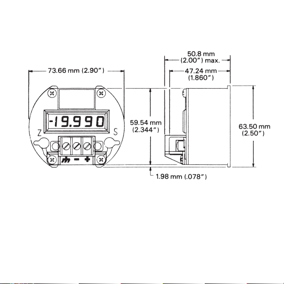
The TX-83 and TX-84 are packaged in a small,
rugged, die-cast, zinc-alloy case designed to fit 3" I.D.
or larger housings, and requiring less than 2" of
height. (Refer to Figure 2-1.)
5
Page 10
6
Figure 2-1. Outline Dimensions
Page 11

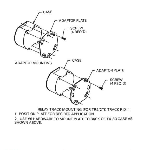
The TX-83 provides for surface, track, or explosionproof housing mounting, and is connected with a
three-terminal, #6 screw barrier strip. Tapped holes
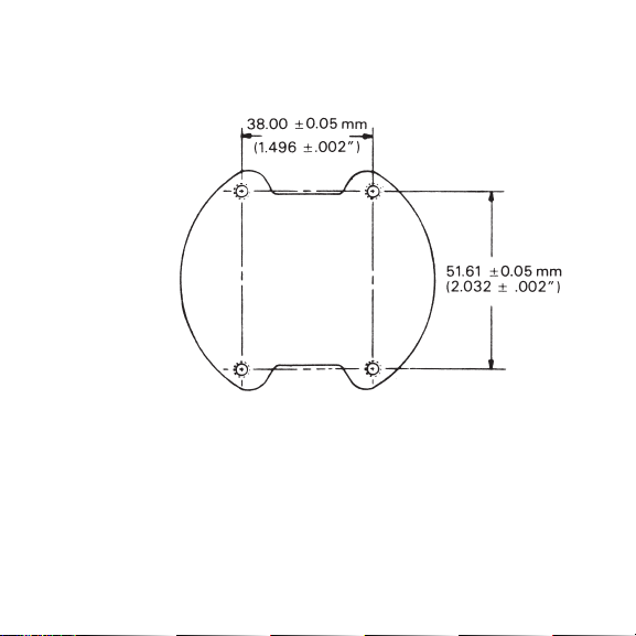
on the back of the TX-83 case provide for custom
mounting to a flat surface; integral flanges on the
back of the case provide for standard 8TK2 relay
track mounting. For flat surface mounting, use #6
hardware For 8TK2 relay track mounting, simply
push onto track.
The TX-83 also comes standard with an additional
adapter plate for surface mount with two #8 frontentry screws through keyhole slots, or for pushmount Into TR2/2TK relay track.
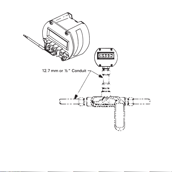
The TX84 is equipped with a
1
⁄2" NPT conduit fitting.
The fitting has two, 0.3 meter long, #18 stranded
insulated wires passing through a neoprene moisture
plug, for hook-up to junction boxes with standard
wire nuts. The TX84-2 is the same as the TX84 with a
1
⁄2" male EMT conduit fitting.
Refer to Figures 2-3a and 2-3b for basic mounting
configurations.
7
Page 12
8
Figure 2-2. Surface and TR2/2TK Relay Track Mounting, Model TX-83
Page 13
9
Figure 2-3a. Rear View: Standard Integral Mounting Plate (TX-83)
Page 14
10
Figure 2-3b. Basic Mounting Configurations
Page 15

2.3 SIGNAL INPUT CONNECTIONS
WARNING
Input currents in excess of protective limits
can damage your TX-83/84 Current Loop
Indicator.
2.3.1 TX-83
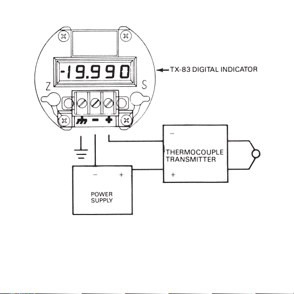
Figure 2-4 below shows a typical TX-83 installation
and wiring when used with a two wire transmitter
and power supply. Power supply requirements are
covered in Section 2-4.
11
Page 16
12
Figure 2-4. TX-83 and Two-Wire Transmitter Wire
Page 17

2.3.2 TXB4
The TX84 comes equipped with a male
1
⁄2" NPT
conduit fitting. The conduit fitting is plugged with a
rubber stopper. Two 0.3 meter (12") long, 18 gage
stranded Insulated wires are passed through the
stopper. The black wire is the positive (+) signal
input and the white wire is the negative (-) signal
input. The unit can be hooked up using standard
wire nuts. The TX84-2 is the some as the TX84 with a
1
⁄2" male EMT conduit fitting.
2.4 POWER SUPPLY REQUIREMENTS
Please refer to Figure 2-4. Current loop powered
transmitters and indicators normally operate well
with both regulated and unregulated power supplies.
The TX83 and TX84 will work well with both.
13
Page 18

The power supply required to power a current loop
circuit is principally dictated by the power demand
of the transmitter rather than the indicator. For our
example, the typical OMEGA thermocouple
transmitter voltage supply specification may read
“12-60 Vdc”, with an implied 20 plus mA current
draw per transmitter. To determine total power
supply voltage needs, add to the 12 Vdc voltage (for
the transmitter) the maximum voltage drop across
the Digital indicator, in this case, 2.5 volts for the
TX-83 or TX-84. This would give a power demand of
14.5 volts and 20 milliamps. (if you were working
with a 50 milliamp loop, the 20 milliamps would
become 50 milliamps).
For the case cited, a safe selection would be an 18
(plus) volt power supply capable of delivering 20 or
more milliamps for each transmitter to be powered.
The economical OMEGA PSU-24, 24 volt 100 mA
unregulated power supply would be an excellent
selection for powering up to 4 of the above.
14
Page 19

SECTION 3 CONFIGURATION PROCEDURES
3.1 GENERAL
The TX-83 and TX-84 are shipped from the factory
with the standard configuration of 4 to 20 mA
(displays 00.0 to 100.0). A custom configuration for
other values of span and zero and/or changes in in
the span slope, decimal point location, or dummy
right-hand zero, may be made in the field by
relocating internal shunt blocks, and adjusting the
zero and span potentiometers (refer to paragraph
3.5). The following Field Set-Up Procedures
(paragraphs 3.3 and 3.4) can be used to determine the
necessary configuration.
3.2 GLOSSARY
The following terms appear throughout the
Configuration Procedures:
15
Page 20

TERM DESCRIPTION
DP1 Decimal Point 1.999
DP2 Decimal Point 19.99
DP3 Decimal Point 199.9
DRHZ Dummy Right-Hand Zero
G Gain Expressed in Counts per mA
I1 Lowest Input Current in mA
I2 Highest Input Current in mA
N1 Reading in Displayed Counts at Input
Current I1
N2 Readling In Displayed Counts at Input
Current I2
FIN Required Flange Number for Zero Range
Selection
RSS Reverse Span Slope
ZR1 Zero Range (- 2510 to -1420)
ZR2 Zero Range (-1580 to -420)
ZR3 Zero Range (-470 to + 850)
ZR4 Zero Range (+ 760 to +2000)
16
Page 21

3.3 FIELD SET-UP CALCULATION PROCEDURE
1. Base all calculations on one of three ranges:
1 to 5 mA, 4 to 20 mA, or 10 to 50 mA.
2. Determine the lowest input current, I1, specified
by user.
I1 = ______________ mA
3. Determine the highest input current, I2, specified
by user.
I2 = ______________ mA
4. Determine the reading, N1, at input current 11,
specified by user.
N1 = _____________ counts
5. Determine the reading, N2, at input current I2,
specified by user.
N2 = _____________ counts
6. Calculate the gain (G1):
(N2 - N1)
G = ------------- = ____________ counts per mA
(I1 - I2)
7. Calculate the required range number:
RN = N1 - (I1 x G)
17
Page 22

NOTE
If G is greater than 500, it is out of the operating
range for a standard unit.
8. Select the zero range (ZR) that includes the
required range number (RN) from the following
ranges:
ZR1 = -2610 to -1420
ZR2 = -1580 to -420
ZR3 = -470 to +850
ZR4 = +760 to +2000
9. Proceed to paragraph 3.5 Field Set-Up Procedure
Implementation.
3.4 ALTERNATE FIELD SET-UP CALCULATION
PROCEDURE
1. (Line 1) Low Signal Input (mA) = _______________.
2. (Line 2) High Signal Input (mA) = ______________.
3. (Line 3) Low Signal Input Reading (Counts) =
____________________.
18
Page 23

4. (Line 4) High Signal Input Reading (Counts) =
____________________.
5. (Line 5) Line 2 - Line I = ____________________.
6. (Line 6) Line 4 - Line 3 = ____________________.
7. (Line 7) Line 6 divided by Line 5 = _____________.
8. (Line 8) Line 7 x Line 1 = ____________________.
9. (Line 9) Line 3 - Line 8 = ____________________.
10.Select a zero range from one of the following,
where the number on Line 9 falls between the
high and low numbers of that ZR range:
ZR1 = -2510 to -1420
ZR2 = -1580 to -420
ZR3 = -470 to +850
ZR4 = +760 to +2000
11.Proceed to 3.5 Field Set-Up Procedure
Implementation.
19
Page 24

3.5 HELD SET-UP PROCEDURE IMPLEMENTATION
The TX-83 and TX-84 factory calibrated configuration
displays 00.0 to 100.0 for an input of 4 to 20 mA.
Internal shunt blocks are factory-installed in
positions J, G, a, and L. A custom configuration for
other values of span and zero and/or changes in the
span slope, decimal point location, or dummy righthand zero is accomplished by relocating internal
shunt blocks as shown in Table 3-1 Configuration
Chart. After the internal shunt blocks are changed,
the Span and Zero potentiometers must be readjusted
as described in paragraph 3.6.2 Calibration
Procedure.
Six shunt blocks are provided with the TX-83 and
TX-84 to accommodate in-field configuration
changes. Unused or spare shunt blocks should be
inserted in a vertical position on unused upper pins
closest to the display board.
To access the shunt blocks, remove the four Phillipshead screws from the top of the TX-83 and TX-84
case, and lift the main unit from the case.
20
Page 25

Refer to Figures 3-1a and 3-1b for shunt block
location and designations.
TABLE 3-1
CONFIGURATION CHART
CONFIGURATION SHUNT BLOCK
LOCATIONS
REQUIRING SHUNT
BLOCKS
1 to 5 mA None
4 to 20 mA J
10 to 50 mA A
Normal Span Slope G and a
Reverse Span Slope (RSS) F and Z
Zero Range
-2510 to -1420 (ZR1) I
Zero Range
-1580 to -420 (ZR2) T
21
Page 26

TABLE 3-1 (Cont’d)
Zero Range
-470 to +850 (ZR3) None
CONFIGURATION SHUNT BLOCK
LOCATIONS
REQUIRING SHUNT
BLOCKS
Zero Range
+ 760 to +2000 (ZR4) c
Dummy Right-Hand Zero
(DRHZ) D
Decimal Point 1.999 (DP1) W
Decimal Point 19.99 (DP2) L
Decimal Point 199.9 (DP3) V
22
Page 27
23
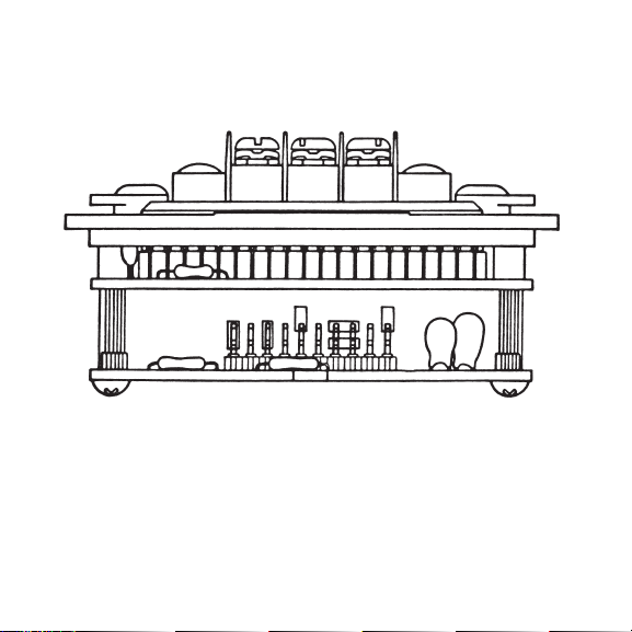
Figure 3-1a. Side View of TX-83/84 with Shunt Blocks Installed for
Standard Configuration (4 mA = 00.0 and 20 mA = 100.0). For Other
Application-Specific Configurations, Installed Shunt Blocks can
have Other Locations
Page 28
24
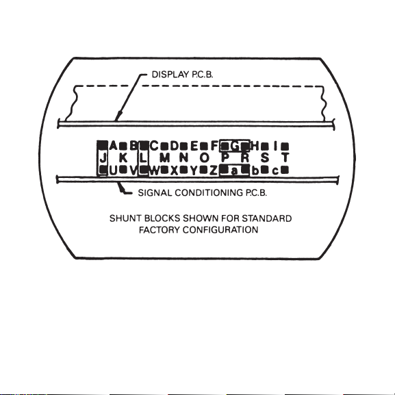
Figure 3-1b. Shunt Block Diagram
Page 29

To proceed with the Field Set-Up Procedure
Implementation:
1. If the current range chosen in either paragraph 3.3
step 1, or paragraph 3.4 step 1 equals either 4 to 20
mA or 10 to 50 mA, install a shunt block as shown
in Table 3-1. Pin forest designations are illustrated
in Figure 3-1b.
2. If N1 (paragraph 3.3 step 4 or paragraph 3.4 step 3) is
more positive than N2 (paragraph 3.3 step 5 or
paragraph 3.4 step 4), reverse the span slope (RSS)
by installing two shunt blocks as shown in Table 3-1.
3. Select the zero range required (ZR1, ZR2, ZR3, ZR4),
and install a shunt block as shown in Table 3-1.
4. If a dummy right-hand zero (DRHZ) is required,
install a shunt block as shown in Table 3-1.
5 If a decimal point is required (DP1, DP2, DP3),
install a shunt block as shown in Table 3-1.
25
Page 30

3.6 CALIBRATION
3.61 Equipment Required
Precision mA power source or, 10 V power supply,
4
1
⁄2 digit DMM with mA range and 10 kilohm
rheostat.
3.6.2 Calibration Procedure
1. Remove the four Phillips-head screws from the top
of the TX-83/84 case and lift main unit from case
2. Select the desired shunt block configuration and
install the push-on shunt blocks in locations
indicated in Table 3-1. (Refer to paragraph 3.5.)
NOTE
Store unused shunt blocks in a vertical position,
on unused upper pins closest to the Display
Board.
26
Page 31

3. Pull off two sealing plugs that cover the Span (S)
and Zero (Z) potentiometer screw heads on the
front of the TX-83/84.
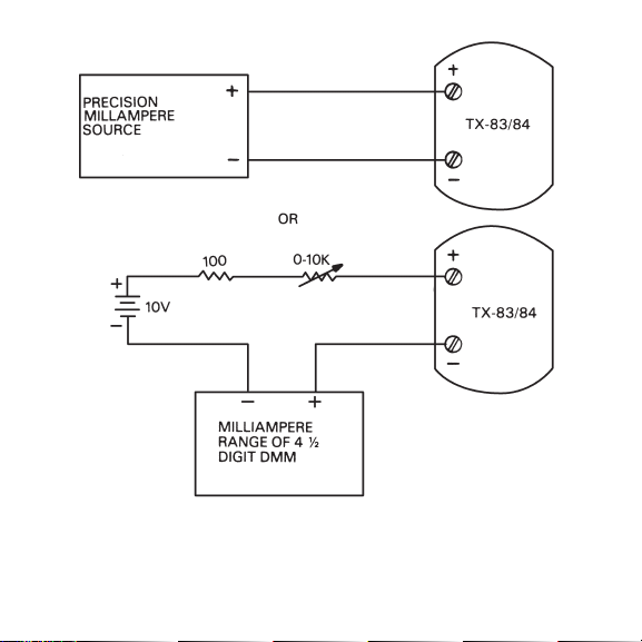
4. Set up the TX-83/84 as shown in Figure 3-2.
5. Calibrate the unit as follows:
A. Alternately apply input currents I1 and I2, and
adjust Span pot (S) until span reading equals N2
- N1 counts.
B. Apply input current I1, and adjust the Zero pot
(Z) until a reading equal to N1 is displayed.
6. Remove the TX-83/84 from the calibration set-up.
7. Replace the two sealing plugs over the Span and
Zero potentiometer screw heads.
8. Apply new labels onto the bottom end side of the
TX-83/84, stating the new values of I1, I2, N1, and
N2.
9. Re-install the TX-83/84 main unit into its case.
27
Page 32
28
Figure 3-2. Calibration Set-Up
Page 33

SECTION 4 SPECIFICATIONS
INPUT
CURRENT: 1-5 mA, 4-20 mA. or 10-50
mA, field selectable by
internal shunt
VOLTAGE DROP: 2.5 V max forward; up to 50
MA
PROTECTION: 250 mA forward; 10DO mA
reverse at 2.5 V
INPUT RESISTANCE: 50 ohms, 1-5 mA range;
12.5 ohms, 4-20 mA range;
5 ohms, 10-50 mA range
29
Page 34

ZERO RANGE: -2510 to +2000 counts; field-
selectable by internal shunts
in four overlapping coarse
ranges, with a 25-turn
potentiometer for
continuous adjustment
within the following
selected ranges: -2510 to
-1420; -1580 to -420; -470 to
+850; and +760 to +2000
SPAN RANGE: 0 to 2000 counts,
continuously adjustable
with 25-turn potentiometer
NORMAL MODE 46 dB min. a 50/60 Hz
REJECTION:
COMMON MODE 120 dB typical, DC to 60 Hz
REJECTION:
COMMON MODE 700 V peak from DC to 60 Hz
VOLTAGE: (meter to case)
30
Page 35

RFI SUSCEPTIBILITY: Less than ± 0.5% of span at
a distance of one meter
from a 2-watt, hand-held
transceiver (approximately
equivalent to 10 V/m field
strength) at frequencies of
27 MHz or 440 MHz
NOTE
Proper lead dress and shielding required.
ACCURACY AT 25°C: Max error: ±0.l% of span ±1
count; Zero Tempco: ±0.1
count/°C typ., ±0.2
count/°C max.; Span
Tempco: ±0.005% of
span/°C typ., ±0.015% if
span/°C max.
DISPLAY TYPE: 7 segment LCD, 8.9 mm
(0.35") high; jumper
selectable decimal point
31
Page 36

OVERRANGE: Three least-significant active
digits blank
ANALOG-TO-DIGITAL CONVERSION
TECHNIQUE: Dual-slope, average-value
with autozero, correction
POLARITY: Determined automatically at
the end of signal integration
period
SIGNAL 100 ms typ.
INTEGRATION
PERIOD:
READING RATE: 2.5/sec
ENVIRONMENTAL
TEMPERATURE: -40 to +85°C
HUMIDITY: To 95% at 40°C
32
Page 37

VIBRATION: 1.52 mm (.06") double
amplitude, 10-W Hz cycled
SHOCK: 55 g, half-sine, 9-13 msec
duration
WATER Watertight to a proof
RESISTANCE: pressure of 35 kPa (5 psi)
MECHANICAL
WEIGHT: 400 g (14 oz)
DIAMETER: 74 mm (2.9")
HEIGHT (INCL. 48 mm (1.9")
BARRIER):
ELECTRICAL TX-83: three-position
CONNECTIONS: terminal barrier strip with
#6 screw wire clamps TX-84:
1
⁄2" NPT male conduit fitting
with two 0.3 meter long
(12") #18 stranded wires
33
Page 38
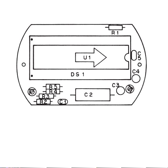
34
Upper P. C. Board Component Layout
Page 39
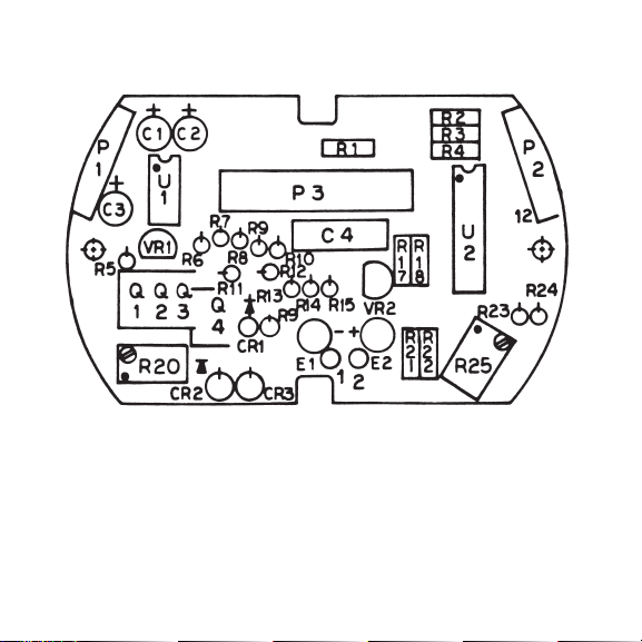
35
Lower P. C. Board Component Layout
Page 40

36
Block diagrams are on the following pages for
TX83 and TX 84 with FM and CSA Approvals for
use in hazardous area with the appropriate
approved intrinsic safety barrier.
Page 41
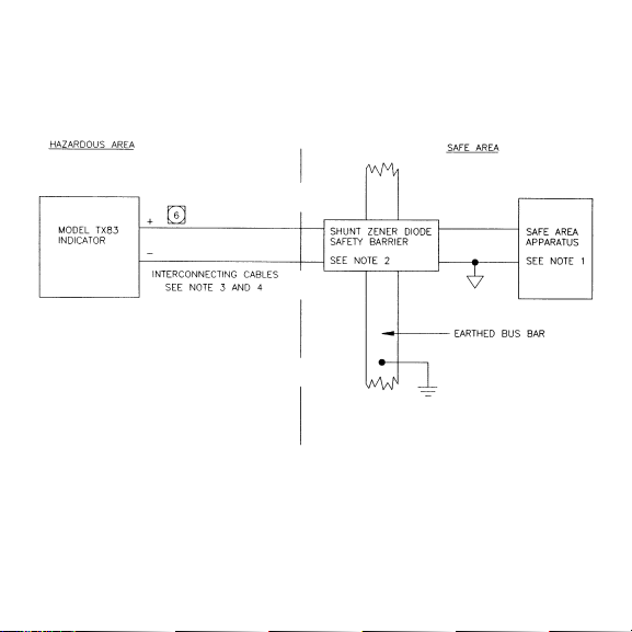
Block Diagram of TX83 - FM Approval
37
Page 42

NOTES
1. APPARATUS WHICH IS UNSPECIFIED EXCEPT THAT IT MUST
NOT BE SUPPLIED FROM NOR CONTAIN UNDER NORMAL OR
ABNORMAL CONDITIONS A SOURCE OF POTENTIAL WITH
RESPECT TO EARTH IN EXCESS OF 250V RMS OR 250VDC.
2. THE FOLLOWING OUTPUT PARAMETERS APPLY;
Vmax=12.5V, Imax=250mA, Ci=8.6µF, Li=0mH
3. THE INTERCONNECTING CABLE MAY BE A TWIN PAIR, OR A
PAIR CONTAINED IN A TYPE A OR TYPE B MULTICORE
CABLE (AS DEFINED IN EN50 039 CLAUSE 5.3) PROVIDED
THAT THE PEAK VOLTAGE OF ANY CIRCUIT CONTAINED
WITHIN THE MULTICORE DOES NOT EXCEED 60 VOLTS.
4. THE CAPACITANCE OR INDUCTANCE OR INDUCTANCE TO
RESISTANCE (4R) RATIO OF THE INTERCONNECTING CABLE
MUST NOT EXCEED THE VALUES SPECIFIED FOR THE
BARRIER IN USE.
5. THE ELECTRICAL CIRCUIT IN THE HAZARDOUS AREA MUST
BE CAPABLE OF WITHSTANDING WITHOUT BREAKDOWN
AN AC TEST VOLTAGE OF 500V RMS TO EARTH OR FRAME
FOR ONE MINUTE.
38
Page 43
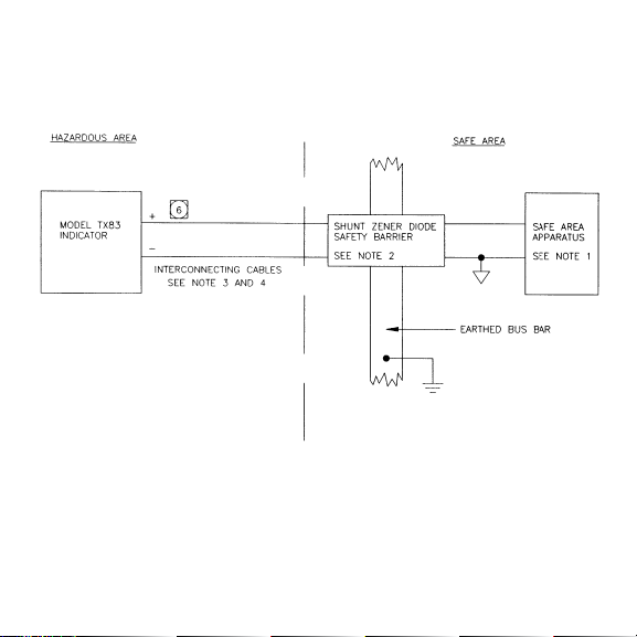
Block Diagram of TX83 - CSA Approval
39
Page 44

NOTES
1. APPARATUS WHICH IS UNSPECIFIED EXCEPT THAT IT MUST
NOT BE SUPPLIED FROM NOR CONTAIN UNDER NORMAL OR
ABNORMAL CONDITIONS A SOURCE OF POTENTIAL WITH
RESPECT TO EARTH IN EXCESS OF 250V RMS OR 250VDC.
2. ANY SHUNT ZENER DIODE SAFETY BARRIER CERTIFIED BY
CSA RATED 28V AT 300Ω.
3. THE INTERCONNECTING CABLE MAY BE A TWIN PAIR, OR A
PAIR CONTAINED IN TYPE A OR TYPE B MULTICORE CABLE
(AS DEFINED IN EN50 O39 CLAUSE 5.3) PROVIDED THAT THE
PEAK VOLTAGE OF ANY CIRCUIT CONTAINED WITHIN THE
MULTICORE DOES NOT EXCEED 60 VOLTS.
4. THE CAPACITANCE OR INDUCTANCE TO RESISTANCE (4R)
RATIO OF THE INTERCONNECTING CABLE MUST NOT
EXCEED THE VALUES SPECIFIED FOR THE BARRIER IN USE.
5. THE ELECTRICAL CIRCUIT IN THE HAZARDOUS AREA MUST
BE CAPABLE OF WITHSTANDING WITHOUT BREAKDOWN
AN AC TEST VOLTAGE OF 500V RMS TO EARTH OR FRAME
FOR ONE MINUTE.
40
6
REVERSING CONNECTIONS WILL NOT DAMAGE UNIT.
Page 45
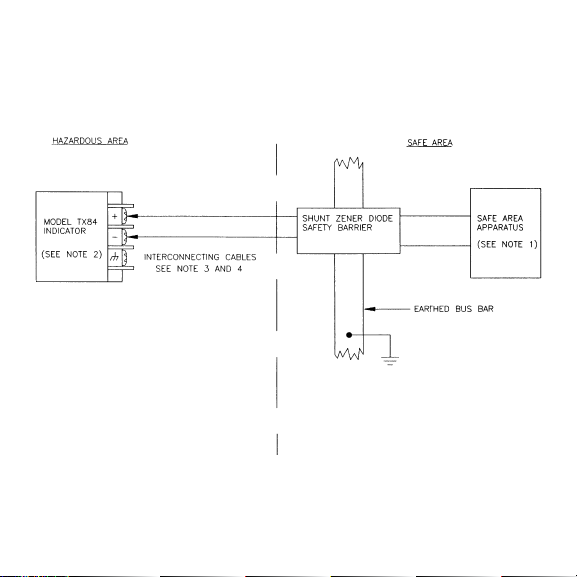
Block Diagram of TX84 - FM Approval
41
Page 46

NOTES
1. APPARATUS WHICH IS UNSPECIFIED EXCEPT THAT IT MUST
NOT BE SUPPLIED FROM NOR CONTAIN UNDER NORMAL OR
ABNORMAL CONDITIONS A SOURCE OF POTENTIAL WITH
RESPECT TO EARTH IN EXCESS OF 250V RMS OR 250VDC.
2. THE FOLLOWING OUTPUT PARAMETERS APPLY; Vmax=12.5V,
Imax=250mA, Ci=8.6µF, Li=0mH
3. THE INTERCONNECTING CABLE MAY BE A TWIN PAIR, OR A
PAIR CONTAINED IN A TYPE A OR TYPE B MULTICORE CABLE
(AS DEFINED IN EN50 039 CLAUSE 5.3) PROVIDED THAT THE
PEAK VOLTAGE OF ANY CIRCUIT CONTAINED WITHIN THE
MULTICORE DOES NOT EXCEED 60 VOLTS.
4. THE CAPACITANCE OR INDUCTANCE TO RESISTANCE (4R)
RATIO OF THE INTERCONNECTING CABLE MUST NOT
EXCEED THE VALUES SPECIFIED FOR THE BARRIER IN USE.
5. THE ELECTRICAL CIRCUIT IN THE HAZARDOUS AREA MUST
BE CAPABLE OF WITHSTANDING WITHOUT BREAKDOWN AN
AC TEST VOLTAGE OF 500V RMS TO EARTH OR FRAME FOR
ONE MINUTE.
42
Page 47
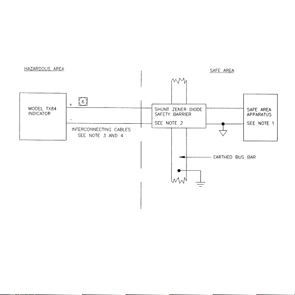
Block Diagram of TX84 - CSA Approval
43
Page 48

NOTES
1. APPARATUS WHICH IS UNSPECIFIED EXCEPT THAT IT MUST
NOT BE SUPPLIED FROM NOR CONTAIN UNDER NORMAL OR
ABNORMAL CONDITIONS A SOURCE OF POTENTIAL WITH
RESPECT TO EARTH IN EXCESS OF 250V RMS OR 250VDC.
2. ANY SHUNT ZENER DIODE SAFETY BARRIER CERTIFIED BY
CSA RATED 28V AT 300Ω.
3. THE INTERCONNECTING CABLE MAY BE A TWIN PAIR, OR A
PAIR CONTAINED IN A TYPE A OR TYPE B MULTICORE CABLE
(AS DEFINED IN EN50 O39 CLAUSE 5.3) PROVIDED THAT THE
PEAK VOLTAGE OF ANY CIRCUIT CONTAINED WITHIN THE
MULTICORE DOES NOT EXCEED 60 VOLTS.
4. THE CAPACITANCE OR INDUCTANCE TO RESISTANCE (4R)
RATIO OF THE INTERCONNECTING CABLE MUST NOT
EXCEED THE VALUES SPECIFIED FOR THE BARRIER IN USE.
5. THE ELECTRICAL CIRCUIT IN THE HAZARDOUS AREA MUST
BE CAPABLE OF WITHSTANDING WITHOUT BREAKDOWN AN
AC TEST VOLTAGE OF 500V RMS TO EARTH OR FRAME FOR
ONE MINUTE.
44
REVERSING CONNECTIONS WILL NOT DAMAGE UNIT
6
Page 49

NOTES:
45
Page 50

NOTES:
46
Page 51

FOR WARRANTY RETURNS, please have the
following information available BEFORE contacting
OMEGA:
1. Purchase Order number under which the
product was PURCHASED,
2. Model and serial number of the product under
warranty, and
3. Repair instructions and/or specific problems
relative to the product.
FOR NON-WARRANTY REPAIRS,
consult OMEGA
for current repair charges. Have the following
information available BEFORE contacting OMEGA:
1.
Purchase Order number to cover the COST
of the repair,
2. Model and serial number of the product, and
3. Repair instructions and/or specific problems
relative to the product.
OMEGA’s policy is to make running changes, not model changes, whenever an improvement is possible. This affords our customers the
latest in technology and engineering.
OMEGA is a registered trademark of OMEGA ENGINEERING, INC.
© Copyright 2003 OMEGA ENGINEERING, INC. All rights reserved. This document may not be copied, photocopied, reproduced, translated, or
reduced to any electronic medium or machine-readable form, in whole or in part, without the prior written consent of OMEGA ENGINEERING, INC.
WARRANTY / DISCLAIMER
OMEGA ENGINEERING, INC. warrants this unit to be free of defects in materials and workmanship for a period
of 25 months from date of purchase. OMEGA’s Warranty adds an additional one (1) month grace period to the
normal two (2) year product warranty to cover handling and shipping time. This ensures that OMEGA’s customers
receive maximum coverage on each product.
If the unit malfunctions, it must be returned to the factory for evaluation. OMEGA’s Customer Service Department will issue
an Authorized Return (AR) number immediately upon phone or written request. Upon examination by OMEGA, if the unit is
found to be defective, it will be repaired or replaced at no charge. OMEGA’s WARRANTY does not apply to defects resulting
from any action of the purchaser, including but not limited to mishandling, improper interfacing, operation outside of
design limits, improper repair, or unauthorized modification. This WARRANTY is VOID if the unit shows evidence of having
been tampered with or shows evidence of having been damaged as a result of excessive corrosion; or current, heat,
moisture or vibration; improper specification; misapplication; misuse or other operating conditions outside of OMEGA’s
control. Components which wear are not warranted, including but not limited to contact points, fuses, and triacs.
OMEGA is pleased to offer suggestions on the use of its various products. However, OMEGA neither
assumes responsibility for any omissions or errors nor assumes liability for any damages that result
from the use of its products in accordance with information provided by OMEGA, either verbal or
written. OMEGA warrants only that the parts manufactured by it will be as specified and free of
defects. OMEGA MAKES NO OTHER WARRANTIES OR REPRESENTATIONS OF ANY KIND
WHATSOEVER, EXPRESS OR IMPLIED, EXCEPT THAT OF TITLE, AND ALL IMPLIED WARRANTIES
INCLUDING ANY WARRANTY OF MERCHANTABILITY AND FITNESS FOR A PARTICULAR PURPOSE
ARE HEREBY DISCLAIMED. LIMITATION OF LIABILITY: The remedies of purchaser set forth herein
are exclusive, and the total liability of OMEGA with respect to this order, whether based on
contract, warranty, negligence, indemnification, strict liability or otherwise, shall not exceed the
purchase price of the component upon which liability is based. In no event shall OMEGA be liable for
consequential, incidental or special damages.
CONDITIONS: Equipment sold by OMEGA is not intended to be used, nor shall it be used: (1) as a “Basic
Component” under 10 CFR 21 (NRC), used in or with any nuclear installation or activity; or (2) in medical
applications or used on humans. Should any Product(s) be used in or with any nuclear installation or activity,
medical application, used on humans, or misused in any way, OMEGA assumes no responsibility as set forth in our
basic WARRANTY/ DISCLAIMER language, and, additionally, purchaser will indemnify OMEGA and hold OMEGA
harmless from any liability or damage whatsoever arising out of the use of the Product(s) in such a manner.
RETURN REQUESTS / INQUIRIES
Direct all warranty and repair requests/inquiries to the OMEGA Customer Service Department. BEFORE RETURNING
ANY PRODUCT(S) TO OMEGA, PURCHASER MUST OBTAIN AN AUTHORIZED RETURN (AR) NUMBER FROM
OMEGA’S CUSTOMER SERVICE DEPARTMENT (IN ORDER TO AVOID PROCESSING DELAYS). The assigned AR
number should then be marked on the outside of the return package and on any correspondence.
The purchaser is responsible for shipping charges, freight, insurance and proper packaging to prevent breakage in transit.
Page 52

TEMPERATURE
Thermocouple, RTD & Thermistor
Probes, Connectors, Panels & Assemblies
Wire: Thermocouple, RTD & Thermistor
Calibrators & Ice Point References
Recorders, Controllers & Process Monitors
Infrared Pyrometers
PRESSURE, STRAIN
AND FORCE
Transducers & Strain Gages
Load Cells & Pressure Gages
Displacement Transducers
Instrumentation & Accessories
FLOW/LEVEL
Rotameters, Gas Mass Flowmeters
& Flow Computers
Air Velocity Indicators
Turbine/Paddlewheel Systems
Totalizers & Batch Controllers
pH/CONDUCTIVITY
pH Electrodes, Testers & Accessories
Benchtop/Laboratory Meters
Controllers, Calibrators, Simulators
& Pumps
Industrial pH & Conductivity Equipment
DATA ACQUISITION
Data Acquisition &
Engineering Software
Communications-Based
Acquisition Systems
Plug-in Cards for Apple, IBM
& Compatibles
Datalogging Systems
Recorders, Printers & Plotters
HEATERS
Heating Cable
Cartridge & Strip Heaters
Immersion & Band Heaters
Flexible Heaters
Laboratory Heaters
ENVIRONMENTAL
MONITORING AND CONTROL
Metering & Control Instrumentation
Refractometers
Pumps & Tubing
Air, Soil & Water Monitors
Industrial Water & Wastewater
Treatment
pH, Conductivity & Dissolved
Oxygen Instruments
Where Do I Find Everything I Need for
Process Measurement and Control?
OMEGA…Of Course!
Shop online at www.omega.com
M0586/0918
 Loading...