

Page 1
An OMEGA Technologies Company
User's Guide
http://www.omega.com
e-mail: [email protected]
TX801D RTD SERIES
PROGRAMMABLE ISOLA TING
DIFFERENTIAL RTDTRANSMITTER
Where Do I Find Everything I Need for
Process Measurement and Control?
OMEGA...Of Course!
TEMPERATURE
Thermocouple, RTD & Thermistor Probes, Connectors, Panels & Assemblies
Wire: Thermocouple, RTD & Thermistor
Calibrators & Ice Point References
Recorders, Controllers & Process Monitors
Infrared Pyrometers
PRESSURE, STRAIN AND FORCE
Transducers & Strain Gauges
Load Cells & Pressure Gauges
Displacement Transducers
Instrumentation & Accessories
FLOW/LEVEL
Rotameters, Gas Mass Flowmeters & Flow Computers
Air Velocity Indicators
Turbine / Paddlesheel Systems
Totalizers & Batch Controllers
pH/CONDUCTIVITY
pH Electrodes, Testers & Accessories
Benchtop/Laboratory Meters
Controllers, Calibrators, Simulators & Pumps
Industrial pH & Conductivity Equipment
DATA ACQUISITION
Data Acquisition & Engineering Software
Communications-Based Acquisition Systems
Plug-in Cards for Apple, IBM & Compatibles
Datalogging Systems
Recorders, Printers & Plotters
HEATERS
Heating Cable
Cartridge & Strip Heaters
Immersion & Band Heaters
Flexible Heaters
Laboratory Heaters
ENVIRONMENTAL
MONITORING AND CONTROL
Metering & Control Instrumentation
Refractometers
Pumps & Tubing
Air, Soil & W ater Monitors
Industrial Water & Wastewater Treatment
pH, Conductivity & Dissolved Oxygen Instruments
M-3798-0302
✔
✔
✔
✔
✔
✔
✔
✔
✔
✔
✔
✔
✔
✔
✔
✔
✔
✔
✔
✔
✔
✔
✔
✔
✔
✔
✔
✔
✔
✔
✔
✔
✔
Page 2

omega.com
TM
OMEGA
OMEGAnet
SM
On-Line Service
http://www.omega.com
Internet e-mail
Servicing Nor th America:
USA: One Omega Drive, Box 4047
ISO 9001 Certified Stamford, CT 06907-0047
Tel: (203) 359-1660 FAX: (203) 359-7700
e-mail: [email protected]
Canada: 976 Bergar
Laval (Quebec) H7L 5A1
Tel: (514) 856-6928 FAX: (514) 856-6886
e-mail: [email protected]
For immediate technical or application assistance:
USA and Canada: Sales Service: 1-800-826-6342 / 1-800-TC-OMEGA
SM
Customer Service: 1-800-622-2378 / 1-800-622-BEST
SM
Engineering Service: 1-800-872-9436 / 1-800-USA-WHEN
SM
TELEX: 996404 EASYLINK: 62968934 CABLE: OMEGA
Mexico and
Latin America: Tel: (95) 800-TC-OMEGASMFAX: (95) 203-359-7807
En Espanol: (203) 359-7803 e-mail: [email protected]
Servicing Europe:
Benelux: Postbus 8034, 1180 LA Amstelveen, The Netherlands
Tel: (31) 20 6418405 FAX: (31) 20 6434643
Toll Free in Benelux: 06 0993344
e-mail: [email protected]
Czech Republic: ul. Rude armady 1868, 733 01 Karvina-Hranice, Czech Republic
Tel: 420 (69) 6311627 FAX: 420 (69) 6311 114
e-mail: [email protected]
France: 9, rue Denis Papin, 78190 Trappes
Tel: (33) 130-621-400 FAX: (33) 130-699-120
Toll Free in France: 0800-4-06342
e-mail: [email protected]
Germany/Austria: Daimlerstrasse 26, D-75392 Deckenpfronn, Germany
Tel: 49 (07056) 3017 FAX: 49 (07056) 8540
Toll Free in Germany: 0130 11 21 66
e-mail: [email protected]
United Kingdom: 25 Swannington Road, P.O. Box 7, Omega Drive,
ISO 9001 Certified Broughton Astley, Leicestershire, Irlam, Manchester,
LE9 6TU, England M44 5EX, England
Tel: 44 (1455) 285520 Tel: 44 (161) 777-661 1
FAX: 44 (1455) 283912 FAX: 44 (161) 777-6622
Toll Free in England: 0800-488-488
e-mail: [email protected]
It is the policy of OMEGA to comply with all worldwide safety and EMC/EMI regulations that apply. OMEGA is constantly
pursuing certification of its products to the European New Approach Directives. OMEGA will add the CE mark to every appropriate
device upon certification.
The information contained in this document is believed to be correct but OMEGA Engineering, Inc. accepts no liability for any errors it
contains, and reserves the right to alter specifications without notice.
WARNING: These products are not designed for use in, and should not be used for, patient connected applications.
OMEGA ENGINEERING, INC. warrants this unit to be free of defects in materials and workmanship for a
period of 13 months from date of purchase. OMEGA Warranty adds an additional one (1) month grace
period to the normal one (1) year product warranty to cover handling and shipping time. This ensures that
OMEGA’s customers receive maximum coverage on each product.
If the unit should malfunction, it must be returned to the factory for evaluation. OMEGA’ s Customer Service
Department will issue an Authorized Return (AR) number immediately upon phone or written request. Upon
examination by OMEGA, if the unit is found to be defective it will be repaired or replaced at no charge.
OMEGA’s W ARRANTY does not apply to defects resulting from any action of the purchaser , including but
not limited to mishandling, improper interfacing, operation outside of design limits, improper repair, or unauthorized modification. This WARRANTY is VOID if the unit shows evidence of having been tampered with
or shows evidence of being damaged as a result of excessive corrosion; or current, heat, moisture or vibration; improper specification; misapplication; misuse or other operating conditions outside of OMEGA’ s control. Components which wear are not warranted, including but not limited to contact points, fuses, and triacs.
OMEGA is pleased to offer suggestions on the use of its various products. However, OMEGA
neither assumes responsibility for any omissions or errors nor assumes liability for any damages
that result from the use of its products in accordance with information provided by OMEGA,
either verbal or written. OMEGA warrants only that the parts manufactured by it will be as
specified and free of defects. OMEGA MAKES NO OTHER WARRANTIES OR REPRESENTATIONS OF ANY KIND WHATSOEVER, EXPRESSED OR IMPLIED, EXCEPT THAT OF
TITLE, AND ALL IMPLIED WARRANTIES INCLUDING ANY WARRANTY OF
MERCHANTABILITY AND FITNESS FOR A PARTICULAR PURPOSE ARE HEREBY DISCLAIMED. LIMITATION OF LIABILITY: The remedies of purchaser set forth herein are
exclusive and the total liability of OMEGA with respect to this order, whether
based on contract, warranty, negliegence, indemnification, strict liability or otherwise, shall not
exceed the purchase price of the component upon which liability is based. In no event shall OMEGA
be liable for consequential, incidental or special damages.
WARRANTY/DISCLAIMER
CONDITIONS: Equipment sold by OMEGA is not intended to be used, nor shall it be used: (1) as a “Basic
Component” under 10 CFR 21 (NRC), used in or with any nuclear installation or activity; or (2) in medical
applications or used on humans, or misused in any way, OMEGA assumes no responsibility as set forth in our
basic WARRANTY/DISCLAIMER language, and additionally , purchaser will indemnify OMEGA and hold
OMEGA harmless from any liability or damage whatsoever arising out of the use of the Product(s) in such a
manner.
RETURN REQUESTS/INQUIRIES
Direct all warranty and repair requests/inquiries to the OMEGA Customer Service Department. BEFORE
RETURNING ANY PRODUCT(S) TO OMEGA, PURCHASER MUST OBTAIN AN AUTHORIZED
RETURN (AR) NUMBER FROM OMEGA’S CUSTOMER SERVICE DEPARTMENT (IN ORDER
TO AVOID PROCESSING DELAYS). The assigned AR number should then be marked on the outside of
the return package and on any correspondence.
The purchaser is responsible for shipping charges, freight, insurance and proper packaging to prevent breakage in transit.
FOR WARRANTY RETURNS, please have the
following information available BEFORE contacting OMEGA:
1. P.O. number under which the product was PUR
CHASED,
2. Model and serial number of the product under
warranty, and
3. Repair instructions and/or specific problems
relative to the product.
FOR
NON-WARRANTY REPAIRS, consult
OMEGA for current repair charges. Have the
following information available BEFORE con
tacting OMEGA:
1. P.O. number to cover the COST of the repair,
2. Model and serial number of product, and
3. Repair instructions and/or specific problems
relative to the product.
OMEGA’s policy is to make running changes, not model changes, whenever an improvement is possible. This affords our customers
the latest in technology and engineering.
OMEGA is a registered trademark of OMEGA ENGINEERING, INC.
Copyright 1996 OMEGA ENGINEERING, INC. All rights reserved. This document may not be copied, photocopied, reproduced,
translated, or reduced to any electronic medium or machine-readable form, in whole or in part, without prior written consent of
OMEGA ENGINEERING, INC.
Page 3
TX801D RTD Programmable
Programmable Isolating
Differential RTD Transmiter
Programmable, Isolating, 3 Wire
RTD Input to DC Current or DC
Voltage Output Transmitter.
Quality Assurance Programme.
The modern technology and strict procedures of the ISO9001 Quality Assurance Programme applied
during design, development, production and final inspection grant long term reliability of the instrument.
Features.
l Field Programmable Input and Output Ranges.
l Bi-Polar Input and Output Ranges.
l Isolated Input to Output 1.6kV.
l High Accuracy & Linearity to 0.1%.
l Linear With Temperature.
l Universal AC/DC Power Supply.
l Compact DIN Rail Mount Enclosure.
l Available Standard or Special Calibration.
ISO9001
E
G
I
S
T
E
R
R
E
D
S
U
P
P
I
R
E
L
Specifications.
RTD Input Pt100 DIN (2 Wire Type) Standard.
Sensor Current = 0.8mA Typical.
Field Programmable Zero From -200C(-400F) to 200C(400F).
Field Programmable Span From 20C(40F) to 600C(1200F).
Other Types of RTD Available:
JIS Pt100, Pt250, Pt500, Pt1000, CU10, CU100, Ni100 or Specified.
Output - Voltage Field Programmable From 500mVdc to ±12Vdc.
Maximum Output Drive = 10mA.
- Current Field Programmable From 1mAdc to ±20mAdc.
Maximum Output Drive = 10Vdc. (500Ω @ 20mA.)
Universal P/S -Standard High (H) 70~270Vac and 80~380Vdc; 50/60Hz; 4VA.
-Standard Mid (M) 24~80Vac and 20~90Vdc; 50/60Hz; 4VA.
-Low Voltage (L) 8~30Vac and 8~30Vdc; 50/60Hz; 4VA.
-Circuit Sensitivity <±0.001%/V FSO Typical.
Accurate to <±0.1% FSO Typical.
Linearity & Repeatability <±0.1% FSO Typical.
Ambient Drift <±0.01%/C FSO Typical.
Noise Immunity 125dB CMRR Average. (1.6kV Peak Limit.)
R.F. Immunity <1% Effect FSO Typical.
Isolation Voltage 1.6kVac/dc Input to Output for 60 sec.
Response Time 200msec Typical. (10 to 90% 50msec Typical.)
Operating Temperature 0~70C.
Storage Temperature -20~80C.
Operating Humidity 90% RH Max. Non-Condensing.
Construction Socket Plug-In Type with Barrier Terminals.
Note 1. Specifications based on Standard Calibration Unit, with RTD 2 at 0C, unless otherwise specified.
Note 2. Due to ongoing research and development designs, specifications, and documentation are subject to change without notification.
No liability will be accepted for errors, omissions or amendments to this specification.
2 1 8 7
3 4 5 6
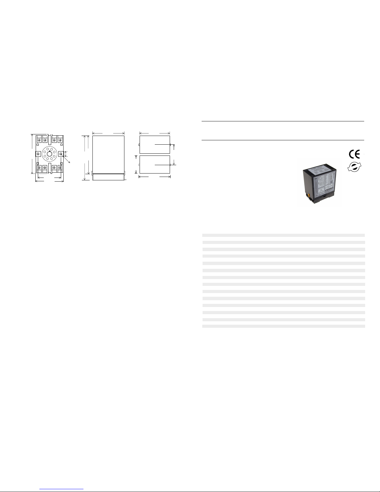
40mm
50mm
80mm
8.4mm
2 x 04.5mm
8PFA Octal Termination Base
Dimensions and Mounting.
80mm
Side View
120mm
Top View
51mm
84mm
80mm
100mm
Top View
58mm
Minimum distance
between units.
The Proper Installation & Maintenance
MOUNTING.
(1) Mount in a clean environment in an electrical cabinet on 35mm, symetrical, mounting rail.
(2) Do not subject to vibration or excess temperature or humidity variations.
(3) Avoid mounting in cabinets with power control equipment.
(4) To maintain compliance with the EMC Directives the TX801D RTD is to be mounted in a fully enclosed steel cabinet. The
cabinet must be properly earthed, with appropriate input / output entry points, filtering and cabling.
WIRING.
(1) A readily accessible disconnect device and overcurrent device must be incorporated in the the power supply wiring.
(2) All cables should be good quality overall screened INSTRUMENTATION CABLE with the screen earthed at one end only.
(3) Signal cables should be laid a minimum distance of 300mm from any power cables.
(4) For 2 wire current loops and 2 wire RTDs, Austral Standard Cables B5102ES is recommended. For three wire transmitters
and 3 wire RTDs Austral Standard Cables B5103ES is recommended.
(5) For differential 2-wire RTD measurement it is important to use identical cables and keep them the same length, so errors
due to cable length are kept minimal.
(6) It is recommended that you do not ground current loops and use power supplies with ungrounded outputs.
(7) Lightning arrestors should be used when there is a danger from this source.
(8) Refer to diagrams for connection information.
RTD'S.
(1) Avoid locating the RTD where it will be in a direct flame.
(2) Locate it where the average temperature will be measured. It should be representative of the mass.
(3) Immerse the RTD so that the measuring point is entirely in the temperature to be measured; 9 to 10 times the diameter
of the protection tube is recommended. Heat that is conducted away from the measuring point causes an error in reading.
COMMISSIONING.
(1) Once all the above conditions have been carried out and the wiring checked apply power and allow five minutes for it
to stabilize.
(2) Due to differences in cable resistance in the RTD legs or errors within the RTD itself a small Zero error may occur (usually
less than 1C). To remove this error use two calibration standard RTDs at the same immersion depths and adjust the
Zero trimpot in the top of the enclosure with a small screwdriver, until the two levels agree. (Clockwise to increase the
output reading and anti-clockwise to decrease the output reading.)
MAINTENANCE.
(1) Check RTDs in place - with the calibration RTDs
at the same immersion depths.
(2) Do it regularly - at least once every 6 months.
(3) Replace defective protection tubes - even if they
look good they may not be fluid or gas tight.
(4) Check cables entering the RTD sensor heads.
Page 4
CegnaRtupnI
FFO2-5StuP
FegnaRtupnI
NO2-5StuP
napS-3S oreZ-4S noitcnuF-5S
1 2 3 4 5 6 1 2 3 4 5 6 1 2 3 4
C02~0F04~0
110000 111111 X
C52~0 F05~0 1 1 1 1 0 0 1 1 1 1 1 1 X
C03~0F06~0 111010 111111X
C04~0 F08~0 1 0 0 0 0 1 1 1 1 1 1 1 X
C05~0F001~0 111001 111111X
C06~0 F021~0 1 1 0 1 0 1 1 1 1 1 1 1 X
*C07~0*F041~0 011101 111111X
C57~0 F051~0 1 1 1 1 0 1 1 1 1 1 1 1 X
C08~0F061~0 000011 111111X
C09~0 F081~0 0 1 0 0 1 1 1 1 1 1 1 1 X
*C001~0*F002~0 110011 111111X
C011~0 F022~0 0 0 1 0 1 1 1 1 1 1 1 1 X
C021~0F042~0 10 10 11 111111 X
*C521~0 *F052~0 1 0 1 0 1 1 1 1 1 1 1 1 X
C051~0F003~0 111011 111111X
C002~0 F004~0 1 0 0 1 1 1 1 1 1 1 1 1 X
*C052~0*F005~0 010111 111111X
C003~0 F006~0 1 1 0 1 1 1 1 1 1 1 1 1 X
C004~0F008~0 001111 111111X
C006~0 F0021~0 1 0 1 1 1 1 1 1 1 1 1 1 X
C01~01-F02~02- 110000 101111 1
C02~01- F04~02- 1 1 1 0 1 0 1 0 1 1 1 1 1
C04~01-F08~02- 111001 101111 1
C02~02- F04~04- 1 0 0 0 0 1 1 1 0 1 1 1 1
C03~02-F06~04- 111001 110111 1
C52~52- F05~05- 1 1 1 0 0 1 0 1 0 1 1 1 1
C05~52-F001~05- 111101 010111 1
C02~03- F04~06- 1 1 1 0 0 1 1 0 0 1 1 1 1
C05~05-F001~001- 110011 10 10 11 1
C001~05- F002~001- 1 1 1 0 1 1 1 0 1 0 1 1 1
C051~05-F003~001- 100111 1010 11 1
C001~001- F002~002- 1 0 0 1 1 1 1 1 0 1 0 1 1
C002~001-F004~002- 110111 110101 1
C002~002- F004~004- 0 0 1 1 1 1 1 1 1 0 1 0 1
C004~002-F008~004- 101111 111010 1
C04~02 F08~04 1 1 0 0 0 0 1 1 0 1 1 1 0
C001~05F002~001 111001 10 10 11 0
C051~05 F003~001 1 1 0 0 1 1 1 0 1 0 1 1 0
C002~001F004~002 110011 1101010
C005~001 F0001~002 0 0 1 1 1 1 1 1 0 1 0 1 0
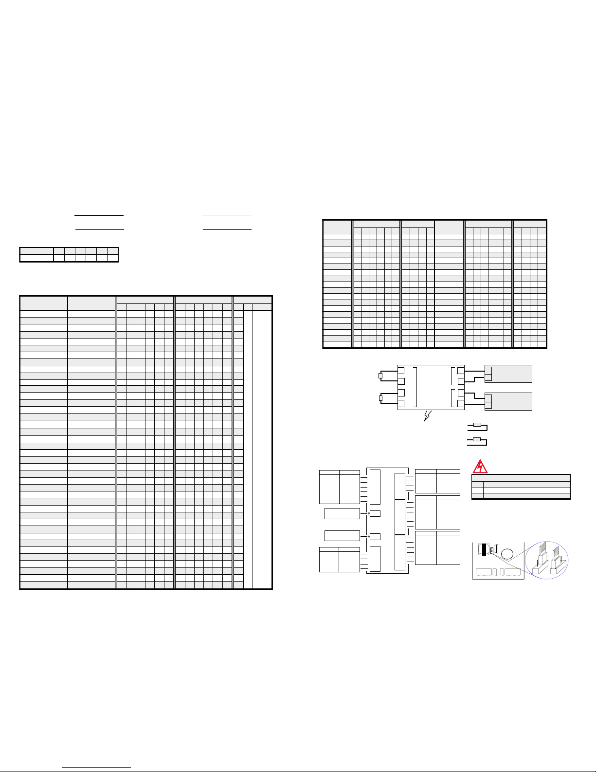
Input Programming.
Always set OUTPUT range first, then INPUT range.
If the Input range is not listed in the programming table, use the following formulae to work out the Zero and Span DIP switch
settings for gain.
Deg C Span Gain = 1200 Deg F Spain Gain = 2400
deg C High - deg C Low deg F High - deg F Low
Deg C Zero Gain = deg C Low Deg F Zero Gain = deg F Low
5 10
If Zero is: 1/ Positive, put S5-1 OFF. 2/ Negative, put S5-1 ON.
Note: (a) Enter the Zero or Span gain value into the appropriate Zero or Span DIP switch.
(b) If the ZERO GAIN exceeds 63, then the input range must be factory calibrated.
Input Range Programming Table.
Notes: 1/ Switch status 1 = ON, 0 = OFF, X = DON'T CARE.
2/ Input ranges with '*' beside them require more adjustment by the Span trimpot.
So if a gain value of 28 is required, put DIP switch No's 3, 4, 5 OFF (ie, gains of
4 + 8 + 16 = 28) and all the other DIP switches ON.
DIP switches and trimpots are accessed by removing the small rectangular lid
on the top of the PI-N enclosure
SET TO '0' FOR CELCIUS. SET TO '1' FOR FAHRENHEIT.
Set to '1' for UPSCALE Sensor Break. Set to '0' for DOWNSCALE Sensor Break.
Set to '0' for UPSCALE Sensor Break. Set to '1' for DOWNSCALE Sensor Break.
eulaVniaG
1 2 4 8 61 23
.oNhctiwSPID
123456
Output Range Programming Table.
Notes: 1/ Switch status 1 = ON 0 = OFF.
2/ Output ranges with '*' beside them reverse the polarity of the output connections.
tuptuO
)V(egnaR
NAPS-1S noitcnuF-2S
tuptuO
)I(egnaR
NAPS-1S noitcnuF-2S
1 2 3 4 5 6 1 2 3 4 1 2 3 4 5 6 1 2 3 4
Vm005~0
011111 0011 Am1~0 011111 0000
V1~0 1 0 1 1 1 1 0 0 1 1 Am2~0 1 0 1 1 1 1 0 0 0 0
V2~0
110111 0011 Am5~0 010111 0000
V3~0 1 0 0 1 1 1 0 0 1 1 Am01~0 1 0 1 0 1 1 0 0 0 0
V4~0
111011 0011 Am61~0 111101 0000
V5~0 1 0 1 0 1 1 0 0 1 1 Am02~0 1 1 0 1 0 1 0 0 0 0
V6~0
110011 0011 Am5~1 110111 1000
V8~0 1 1 1 1 0 1 0 0 1 1 Am01~2 1 1 1 0 1 1 1 0 0 0
V01~0
110101 0011 Am02~4 111101 1000
V21~0 1 1 1 0 0 1 0 0 1 1 Am1~1- 1 0 1 1 1 1 0 1 0 0
V5~1
111011 1011 Am2~2- 110111 0100
V01~2 1 1 1 1 0 1 1 0 1 1 Am5~5- 1 0 1 0 1 1 0 1 0 0
V1~1-
110111 0111 Am01~01- 110101 0100
V2~2- 1 1 1 0 1 1 0 1 1 1 Am02~02- 1 1 1 0 1 0 0 1 0 0
V5~5-
110101 0111 *Am01-~0 1010 11 0000
V01~01- 1 1 1 0 1 0 0 1 1 1 *Am02-~0 1 1 0 1 0 1 0 0 0 0
V21~21-
111100 0111
*V5-~0 1 0 1 0 1 1 0 0 1 1
*V01-~0 110101 0011
Terminations.
Output 1 +Ve Input 3 A
2 -Ve 4 B
P/S 7 ~AC/+DC 5 A
8 ~AC/-DC 6 B
RTD 2
RTD 1
3
4
5
6
A
B
A
B
Power
Supply
Input
2
1
8
7
Output
RTD 1
2 wire
RTD 2
2 wire
−
+
∼
−
∼
+
1600V Isolation
AC/DC Power
Source.
+
Eg. Indicator, 2100-M,
etc. With Voltage or
Current Input.
~
~
+
ON
1
2
3
4
5
6
S1-Span
ON
1
2
3
4
S2-Function
OFF ON
Gain = 1 Gain = 0
Gain = 2 Gain = 0
Gain = 4 Gain = 0
Gain = 8 Gain = 0
Gain =16 Gain = 0
Gain =32 Gain = 0
25 Turn Trimpot
for Span ±10%
OFF
ON
0% Offset +20%
Offset
0% Offset -50% Offset
Current O/P Voltage O/P
Current O/P Voltage O/P
Zero
25 Turn Trimpot
for Zero ±10%
Plan View of Adjustments. H1 Power Supply Link Settings.
OUTPUT PROGRAMMING INPUT PROGRAMMING
Span
S
Z
10.04-2
6
5
4
3
2
1
ON
OFF ON
Gain = 32 Gain = 0
Gain = 16 Gain = 0
Gain = 8 Gain = 0
Gain = 4 Gain = 0
Gain = 2 Gain = 0
Gain = 1 Gain = 0
S3-Span
6
5
4
3
2
1
ON
S4-Zero
OFF ON
Gain = 32 Gain = 0
Gain = 16 Gain = 0
Gain = 8 Gain = 0
Gain = 4 Gain = 0
Gain = 2 Gain = 0
Gain = 1 Gain = 0
S5-Function
4
3
2
1
ON
OFF ON
DownscaleUpscale
Upscale Downscale
CF
Poss Zero Neg Zero
sgnitteSkniLylppuSrewoP
1H egnaRegatloVylppuSrewoP
HcdV083~08/caV072~07:hgiHrofkniL
M cdV09~02/caV08~42:diMrofkniL
WARNING: High Voltages Maybe Present.
Only adjust link with power
disconnected.
Notes:
1/ H1 is approx 4cm (1½") behind the 'S' trimpot.
2/ Exceeding voltage ranges may damage the unit.
3/ Ensure the enclosure label is correctly labelled for the
link position.
4/ Adjust H1 jumper with a pair of needle nose pliers.
5/ Low Voltage Power Supply version is fixed, and has
no link. This must be ordered separately.
S2-FUN C TS1-SPA N S Z
H
M
H1
H
M
MID HIGH
 Loading...