

Page 1
User’s Guide
Shop online at
omega.com
e-mail: [email protected]
For latest product manuals:
omegamanual.info
MADE IN ISRAEL
TX69
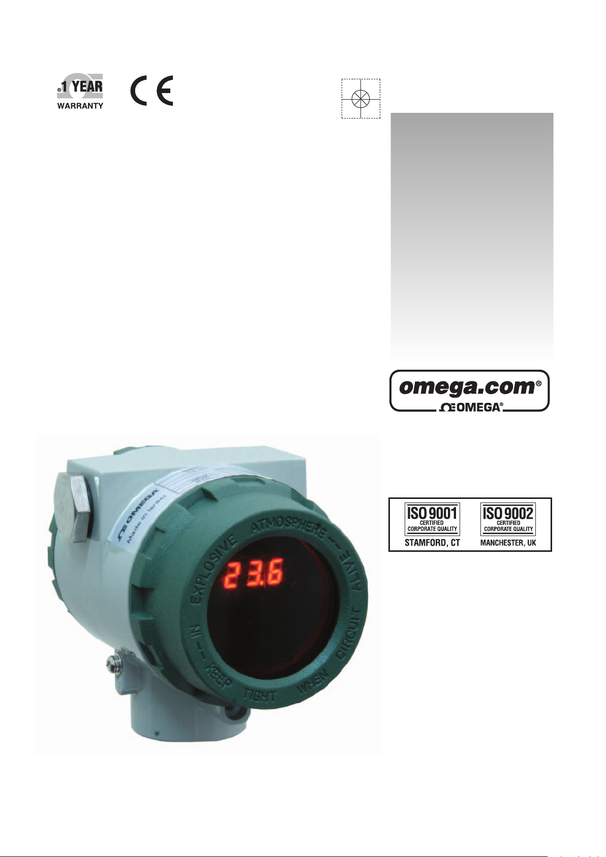
Universal Smart Transmitter
Page 2

OMEGAnet®Online Service Internet e-mail
omega.com [email protected]
Servicing North America:
U.S.A.:
ISO 9001 Certified Stamford, CT 06907-0047
Canada: 976 Bergar
One Omega Drive, P.O. Box 4047
TEL: (203) 359-1660
FAX: (203) 359-7700
e-mail: [email protected]
Laval (Quebec) H7L 5A1, Canada
TEL: (514) 856-6928
FAX: (514) 856-6886
e-mail: [email protected]
m
For immediate technical or application assistance:
U.S.A. and Canada: Sales Service: 1-800-826-6342/1-800-TC-OMEGA
Customer Service: 1-800-622-2378/1-800-622-BEST
Engineering Service: 1-800-872-9436/1-800-USA-WHEN
Mexico: En Espan˜ ol: (001) 203-359-7803
FAX: (001) 203-359-7807
e-mail: [email protected]
[email protected]
®
®
®
Servicing Europe:
Czech Republic: Frystatska 184, 733 01 Karviná, Czech Republic
TEL: +420 (0)59 6311899
FAX: +420 (0)59 6311114
Toll Free: 0800-1-66342
e-mail: [email protected]
Germany/Austria: Daimlerstrasse 26, D-75392 Deckenpfronn, Germany
TEL: +49 (0)7056 9398-0
FAX: +49 (0)7056 9398-29
Toll Free in Germany: 0800 639 7678
e-mail: [email protected]
United Kingdom: One Omega Drive, River Bend Technology Centre
ISO 9002 Certified Northbank, Irlam, Manchester
M44 5BD United Kingdom
TEL: +44 (0)161 777 6611
FAX: +44 (0)161 777 6622
Toll Free in United Kingdom: 0800-488-488
e-mail: [email protected]
It is the policy of OMEGA Engineering, Inc. to comply with all worldwide safety and EMC/EMI
regulations that apply. OMEGA is constantly pursuing certification of its products to the European Ne
Approach Directives. OMEGA will add the CE mark to every appropriate device upon certification.
The information contained in this document is believed to be correct, but OMEGA accepts
no liability for any errors it contains, and reserves the right to alter specifications without notice.
WARNING: These products are not designed for use in, and should not be used for, human applications.
w
Page 3
Omega Engineering Inc
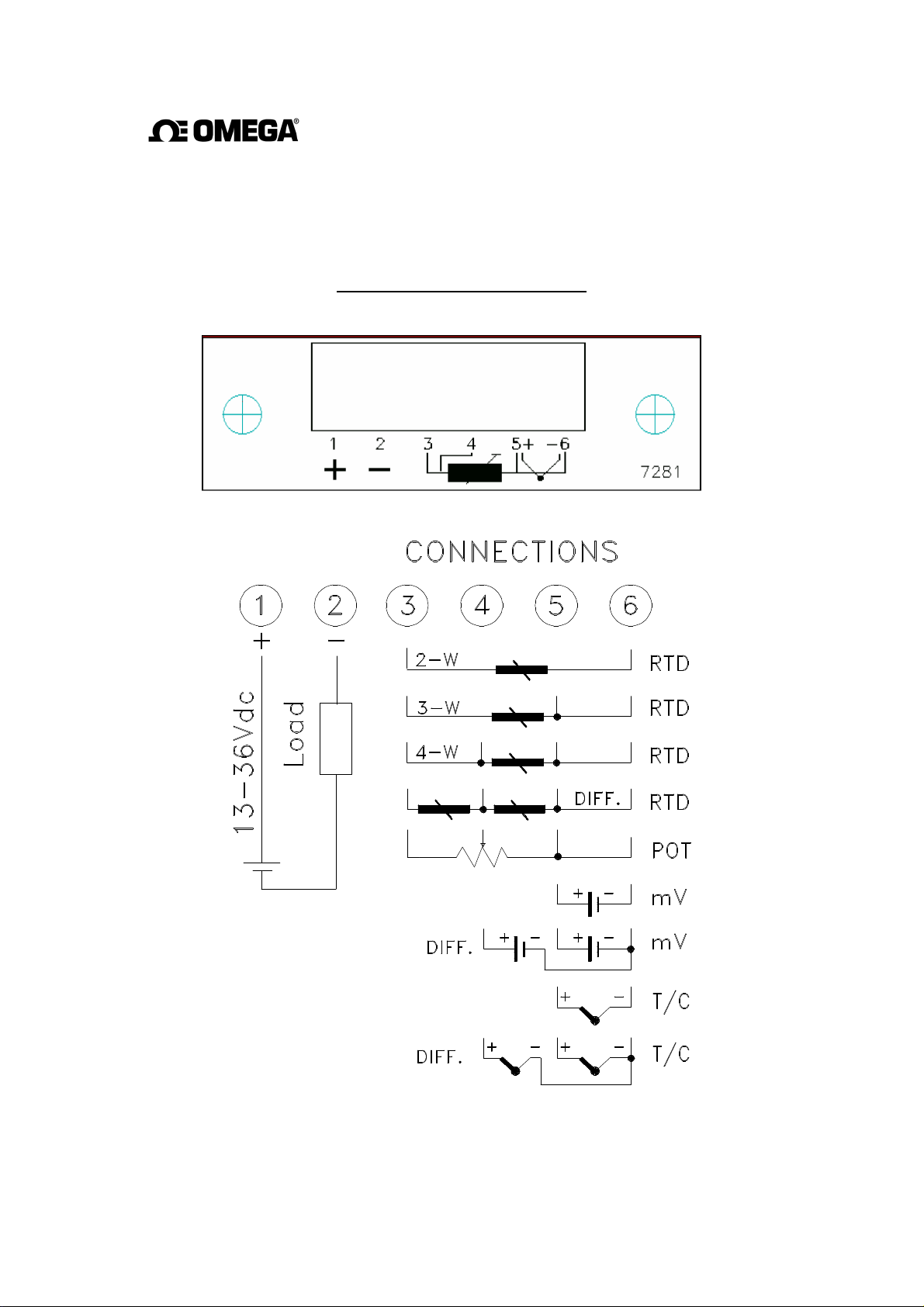
TX-69
CONNECTION DIAGRAM
Page 4

1. PRELUDE : ........................................................................................................................................... 3
2. ESTABLISHING THE COMMUNICATION
:................................................................................ 3
3. NEW CONFIGURATION :
............................................................................................................... 4
3.1.
OPEN NEW CONFIGURATION WINDOW : .................................................................................... 4
3.2.
OPEN EXISTING CONFIGURATION :............................................................................................. 4
4. STRUCTURE OF THE CONFIGURATION WINDOW :
............................................................ 5
4.1.
GENERAL INFORMATION TAB :................................................................................................... 5
4.2.
SENSOR TAB :.............................................................................................................................. 6
4.2.1. RTD:
............................................................................................................................... 6
4.2.2. Thermocouple:
............................................................................................................... 7
4.2.3. Voltage:
.......................................................................................................................... 7
4.2.4. Potentiometer:
................................................................................................................ 7
4.2.5. Resistor :
........................................................................................................................ 8
4.3.
INPUT / OUTPUT RANGE TAB : ................................................................................................ 8
4.3.1. Input Range :
.................................................................................................................. 9
4.3.2. Output Range :
............................................................................................................... 9
4.3.3. Display Range:…………………………………………………………………… 10
4.3.4. Burn-Out Output :
........................................................................................................ 10
4.4.
SET-UP TAB : ............................................................................................................................ 11
4.4.1. Mode :
........................................................................................................................... 11
4.4.2. Damping Time :
........................................................................................................... 11
5. CONFIGURATION SAVE:
.............................................................................................................. 11
6. UPDATING THE UNIT
:…………………………………………………… …………….….... 12
7. CORRECTIONS :
.............................................................................................................................. 14
7.1 OFFSET CORRECTION
: ……………………………………………………………………….. 14
7.2 SLOPE CORRECTION: …………………………………………………………………………… 15
8. ADDITIONAL FEATURES:………………………………..…………………………….……. 16
8.1 RESETTING THE EXTREME MEASUREMENTS
: …………… … ….....……….……. 16
8.2 PRINT :…………………… ………………………………………………………………………… 16
2
Page 5
1.
Pr
elude :
The CONCAL software provides communication with the TX69 transmitter for
setting its configuration. The parameters to be configured are - sensor type,
measurement range, display reading etc.
2.
Establishing the
Communication :
The TX69 communicates via USB ports.
When the unit is connected to any of the USB ports, the software automatically
searches the connected port in order to communicate thru.
In case that the selected USB port is other than the one the software remembers, it
will search the new one and it might take several seconds.
There are three ways to set the communication:
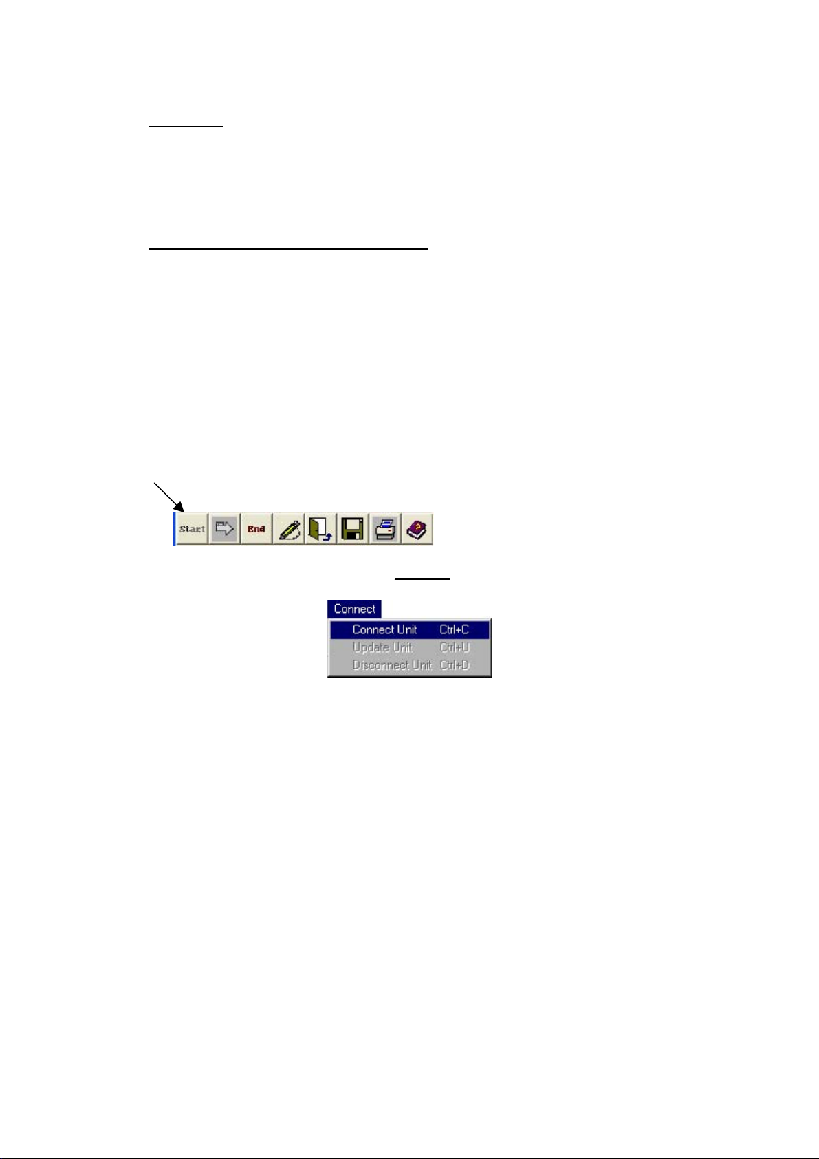
• Click the “Start” button from the Toolbar
• Select “Connect Unit” from the
Connect
on the menu line.
• Type Ctrl+C
The communication procedure consists of several steps:
1. Identification of the connected unit
2. Import of the existing configuration
3. Monitoring of the unit's current measurements
Two windows will be opened:
• "Connected Unit Configuration" - Displays the present configuration
• "Present Reading" - The measurements are displayed at 1-3
seconds rate.
3
Page 6
3.
New Configuration:
In order to set/change the unit’s configuration, the configuration window must be
open.
There are two ways configure the unit:
• Opening "New Configuration" window
• Opening of present configuration window
In both ways the same window is reached but the information is different.
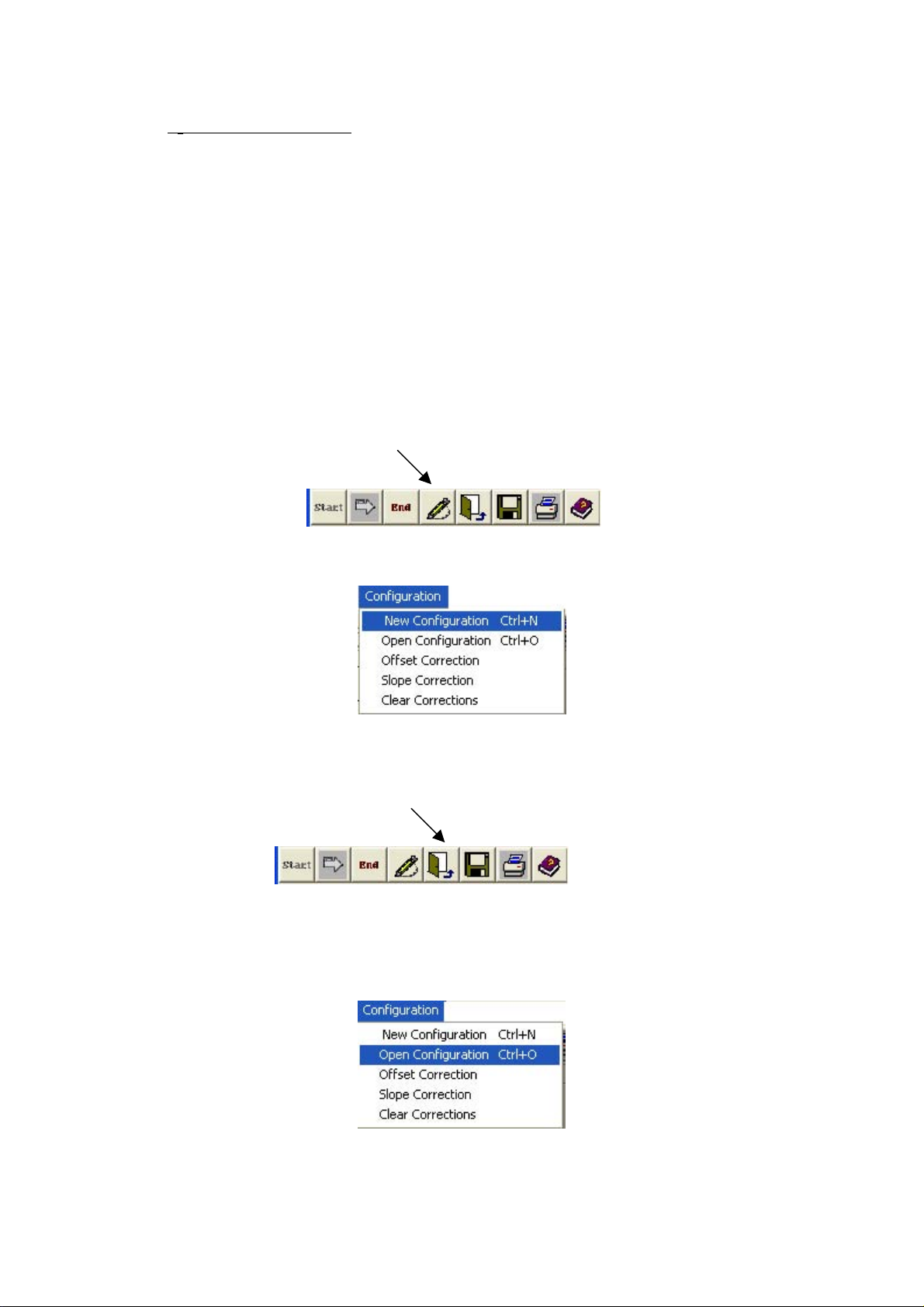
3.1. Open "New Configuration" Window :
• The “New Configuration” button.
Or
• Select “New Configuration” option from the "Configuration" tab.
3.2 Open Existing Configuration :
Click the “Open Configuration” button.
or
• Select “Open Configuration” option from the Configuration menu.
The file containing previous configurations will appear. Double click on the required
file and the configuration box will appear containing the required configuration.
4
Page 7
4.
Structur
e of
The Configuration
W
indow :
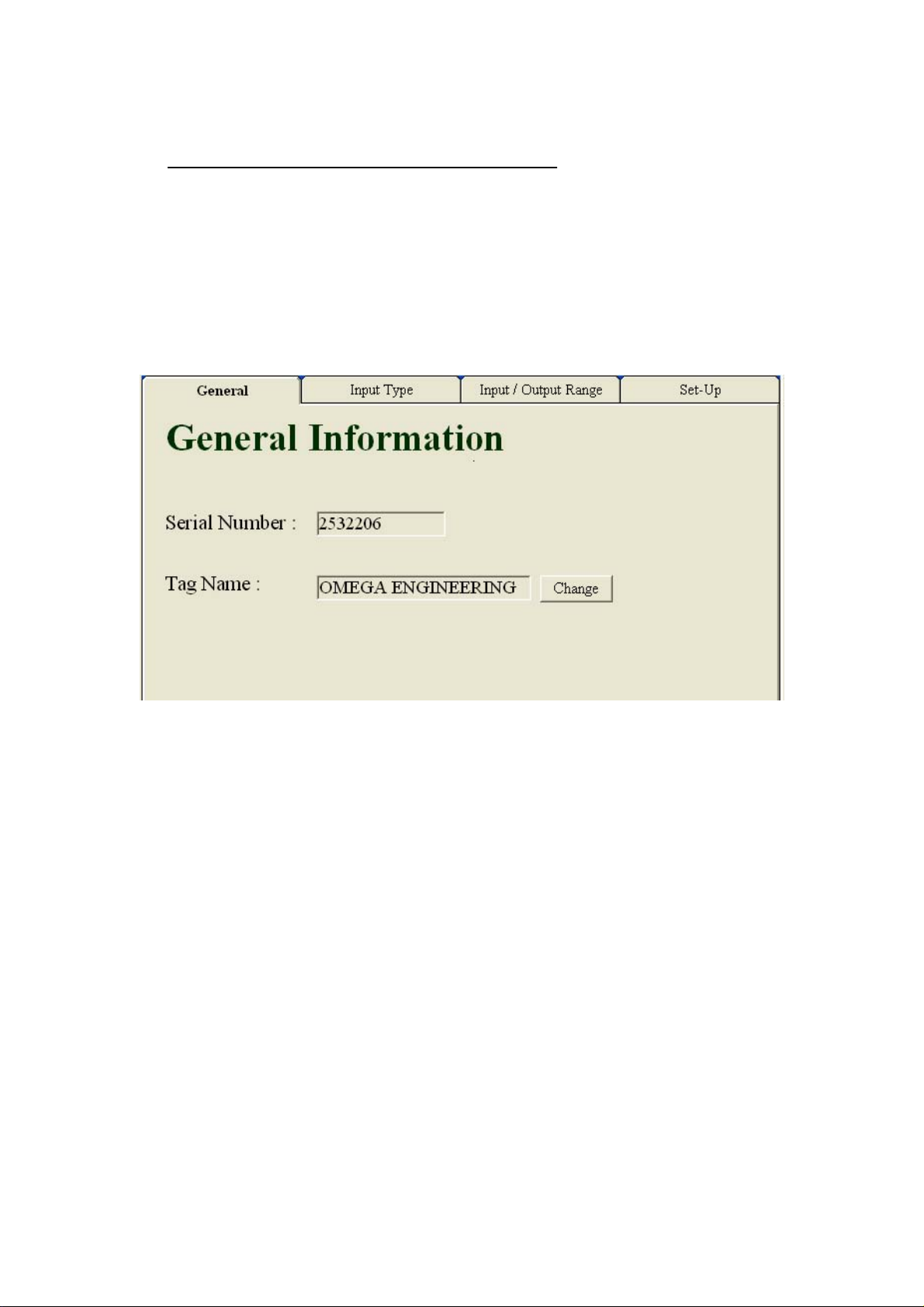
The configuration window contains four tabs:
4.1 General Information Tab
4.2 Sensor Tab
4.3 Input / Output Tab
4.4 Set-Up Tab
4.1. General Tab :
This tab is the unit's ID.
It consists of two fields:
Serial Number - The unit’s serial number, which is set by the factory and can not
be altered.
Tag Name - This field is a 19 character alphanumeric string which can be set by
the operator and be altered any time.
In order to change the contents of the tag name field, first click the
‘Change’ button.
Clicking the ‘Change’ button opens up a text field icon which the proper tag name can
be inserted.
At the end of the updating procedure, the following options are available:
Done - Saves the new contents of the field.
Cancel - Retrieves the previous configuration.
5
Page 8
After selecting one of the two options, the tab returns to its original form. Any
changes within the field make the field’s header to turn red helping the operator to
recognize the changes.
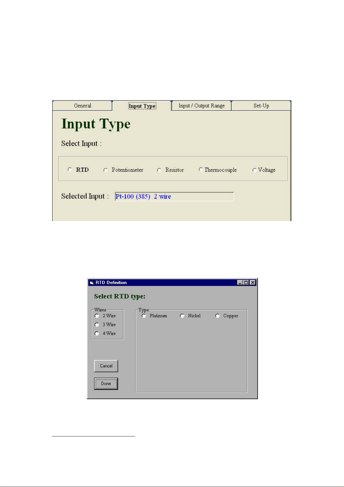
4.2. Input Tab:
The Input tab enables the operator to set the unit for the required input type.
The selected type appears in bold letters.
4.2.1. RTD:
By selecting RTD, the following window opens up :
This window provides selecting of the exact parameters of the required RTD sensor.
1
1
During the procedure other fields would open up according to the specifics of the wanted sensor.
6
Page 9
At the end of the updating procedure, the following options are
available:
Done - Saves the new contents of the field.
Cancel - Retrieves the previous configuration.
After selecting one of the two options, the tab returns to its original form. Any
changes within the field make the field’s header to turn red helping the operator to
recognize the changes.
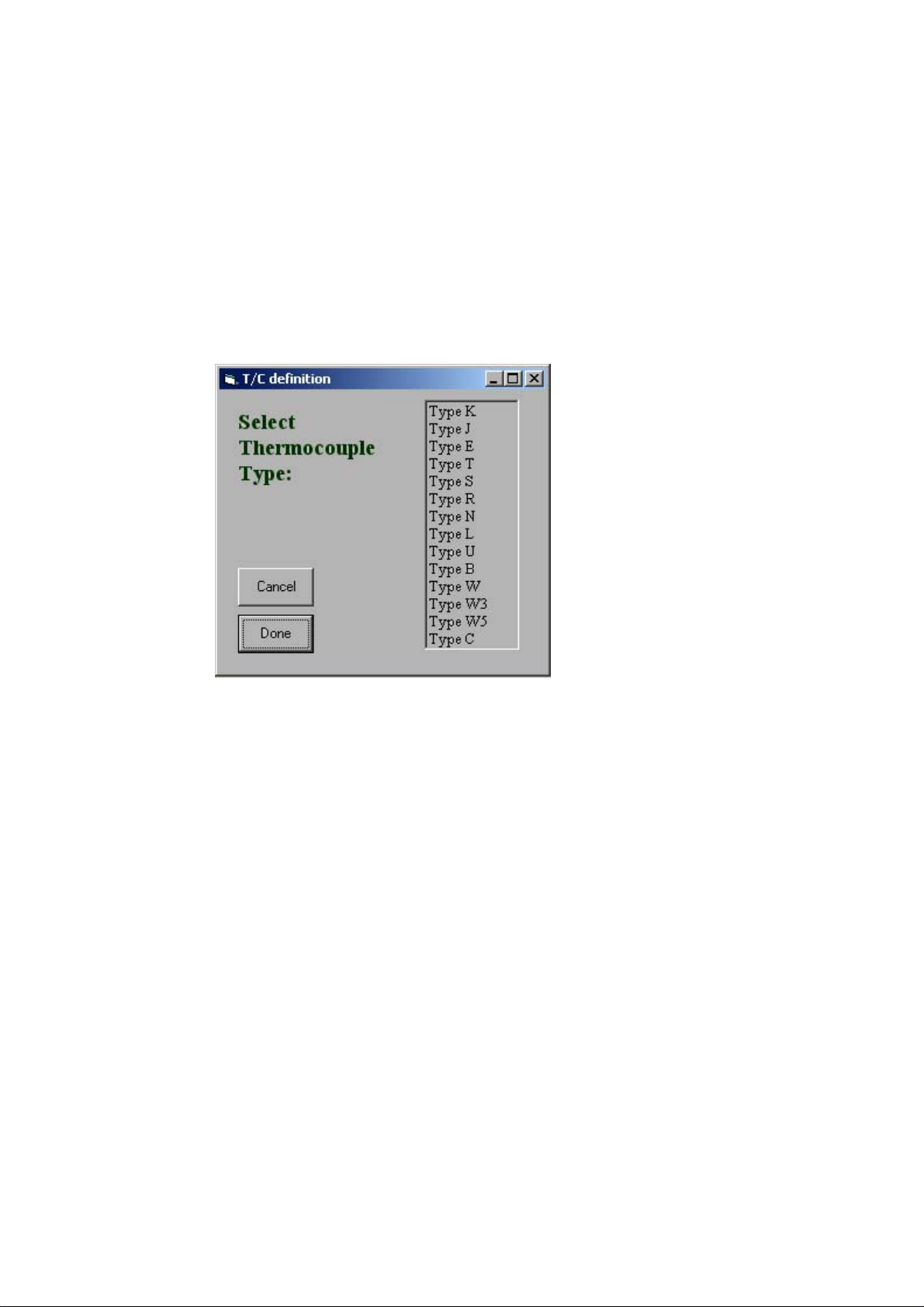
4.2.2. Thermocouple:
By selecting Thermocouple, the following window opens up :
In this window the operator can select the required thermocouple sensor from the list.
At the end of the updating procedure, the following options are
available:
Done - Saves the new contents of the field.
Cancel - Retrieves the previous configuration.
After selecting one of the two options, the tab returns to its original form. Any
changes within the field make the field’s header to turn red helping the operator to
recognize the changes.
4.2.3. Voltage:
These types of sensors do not require any further specifications.
4.2.4. Potentiometer:
By selecting the Potentiometer input, the following window opens up:
7
Page 10
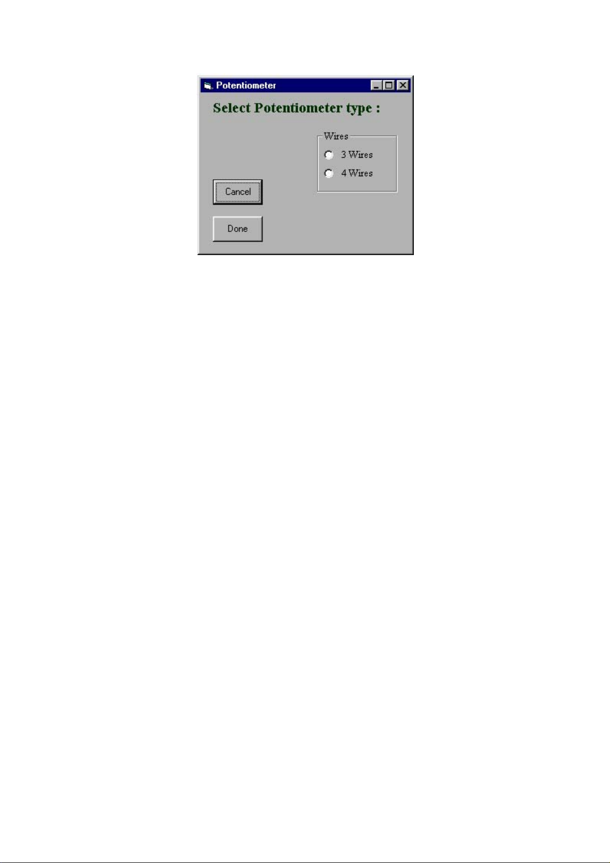
In this window the operator can select the required potentiometer connection type.
At the end of the updating procedure, the following options are
available:
Done - Saves the new contents of the field.
Cancel - Retrieves the previous configuration.
After selecting one of the two options, the tab returns to its original form. Any
changes within the field make the field’s header to turn red helping the operator to
recognize the changes.
4.2.5. Resistor:
By selecting the Resistor input, the following window opens up :
In this window the operator can select the required resistor connection type.
At the end of the updating procedure, the following options are
available:
Done - Saves the new contents of the field.
Cancel - Retrieves the previous configuration.
After selecting one of the two options, the tab returns to its original form. Any
changes within the field make the field’s header to turn red helping the operator to
recognize the changes.
4.3 Input / Output Range Tab :
In this tab the operator can configure the input and output ranges as required.
8
Page 11
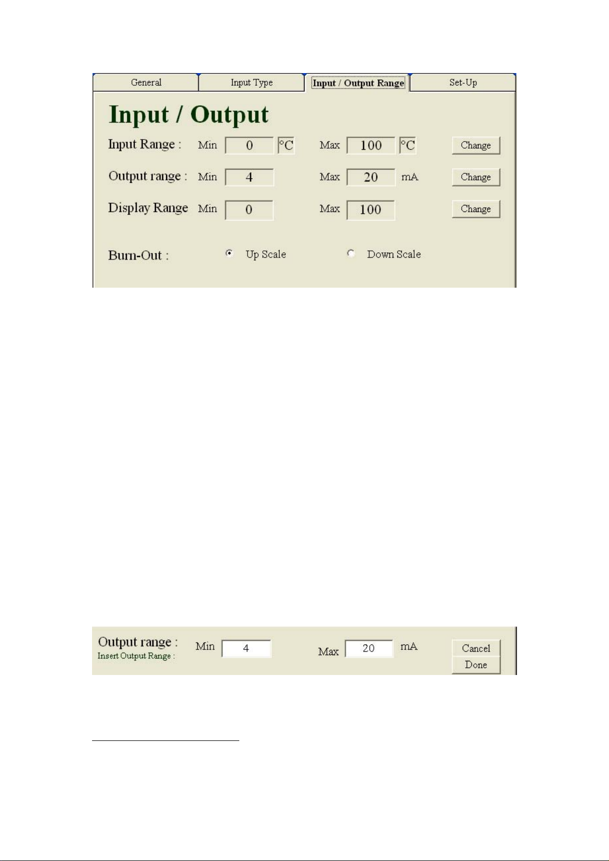
4.3.1. Input Range:
The input range field enables the operator to specify the measurements range for the
transmitter.
Clicking the ‘Change’ button opens up text fields for the minimum and maximum
points of the range.
2
At the end of the updating procedure, the following options are
available:
Done - Saves the new contents of the field.
Cancel - Retrieves the previous configuration.
Exceeding the maximum specified value for a specific sensor will generate
announcement and prevent setting that range.
After selecting one of the two options, the tab returns to its original form. Any
changes within the field make the field’s header to turn red helping the operator to
recognize the changes.
4.3.2. Output range:
The output range field enables setting the TX69 current output.
The configuration can be any pair of values between 4 to 20 or 20 to 4 mA.
3
In order to set this field, click the ‘Change’ button.
Clicking the ‘Change’ button opens up text fields for the minimum and maximum
points of the output range.
2
For Potentiometer type sensors, the ‘Change’ button is unavailable
since the range is constant: 0% - 100%.
3
It is possible to determine the current’s modification with an increasing value or decreasing value
(example: 4-20mA or 20-4mA).
9
Page 12

Note: The Min or Max is to be understood as the output current at the minimum or
maximum input range points.
At the end of the updating procedure, the following options are
available:
Done - Saves the new contents of the field.
Cancel - Retrieves the previous configuration.
After selecting one of the two options, the tab returns to its original form. Any
changes within the field make the field’s header to turn red helping the operator to
recognize the changes.
4.3.3. Display Range:
This feature allows the user to determine the values to be displayed.
As a default, the Display field will be the same as the Input field.
In order to display physical units other then the input but still linear with, press the
"Change" button and insert the Minimum and the Maximum desired values to be
displayed at the minimum and the maximum input points.
At the end of the updating procedure, the following options are
available:
Done - Saves the new contents of the field.
Cancel - Retrieves the previous configuration.
After selecting one of the two options, the tab returns to its original form. Any
changes within the field make the field’s header to turn red helping the operator to
recognize the changes.
4.3.4. Burn-Out Output:
The burn-out field enables to define which value would be output by the transmitter in
case of mal function with the sensor..
Up Scale - Output current grater than 20mA.
Down Scale - Output current lower that 4mA.
At the end of the updating procedure, the following options are
available:
Done - Saves the new contents of the field.
Cancel - Retrieves the previous configuration.
After selecting one of the two options, the tab returns to its original form. Any
changes within the field make the field’s header to turn red helping the operator to
recognize the changes.
4.4 Set-Up Tab:
10
Page 13
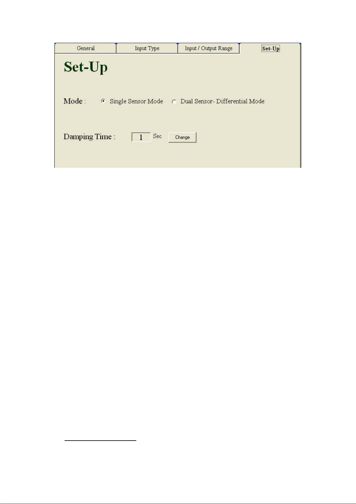
In this tab the operator can define a few general configurations.
The setting contains the following fields:
4.4.1 Mode:
The Mode option provides selecting of single or dual sensor (in differential mode)
input.
Single Mode- One sensor is connected.
Dual Sensor – Differential Mode – Two sensors are connected. The transmitter
outputs the difference between them.
4.4.2 Damping Time:
The damping time field provides integration time in seconds.
In order to update this field, click the ‘Change’ button.
Clicking the ‘Change’ button opens up text fields for the period on which the
moderation would be.
There are 2 possible ranges in this field:
No Damping Time - By selecting the value 0 no integration will take place.
Damping Time - By selecting value 1-100 the operator sets the integration period
At the end of the updating procedure, the following options are
available:
Done - Saves the new contents of the field.
Cancel - Retrieves the previous configuration.
After selecting one of the two options, the tab returns to its original form. Any
changes within the field make the field’s header to turn red helping the operator to
recognize the changes.
5.
Configuration Save:
The configuration save procedure can be accomplished by ether of the 2 following
11
Page 14
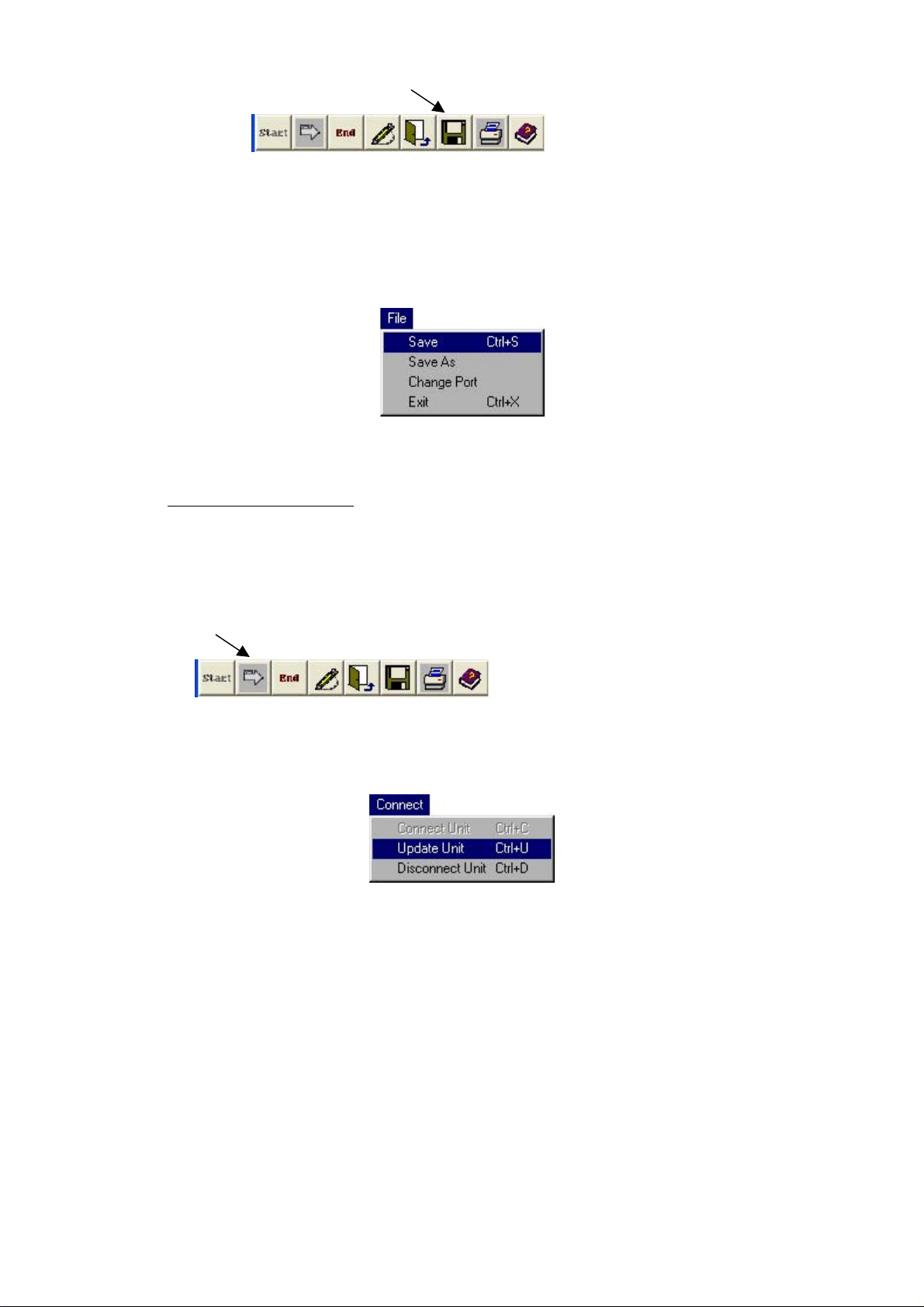
methods:
• The “Save” button.
or
• Select “Save” option from the File menu.
The file should be saved in a dedicated folder.
6.
Updating
The
Unit :
When the setting phase is completed, the TX69 should be updated.
The updating procedure can be accomplished by ether of the two following methods:
• The “Update Unit” button.
Or
• Select “Update Unit” option from the Connect menu.
12
Page 15
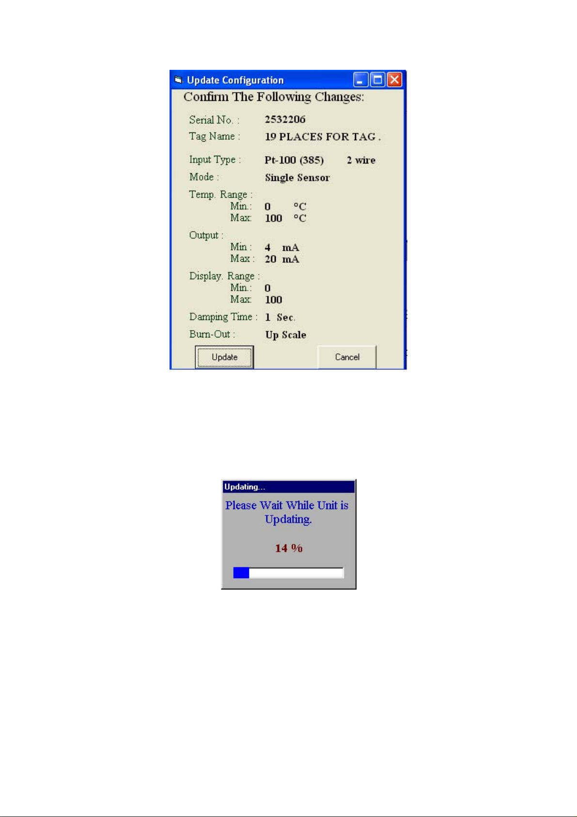
Click the “Update” button to proceed with the updating procedure.
“Updating…” window appears indicating the process progress.
.
13
Page 16
7.
Corr
ections
:
This feature allows the operator to change the factory calibration.
This function is useful to set a probe-transmitter calibrated pair or set a matched
balance between several measuring points.
There are two types of user changes:
• Offset correction
• Slope correction
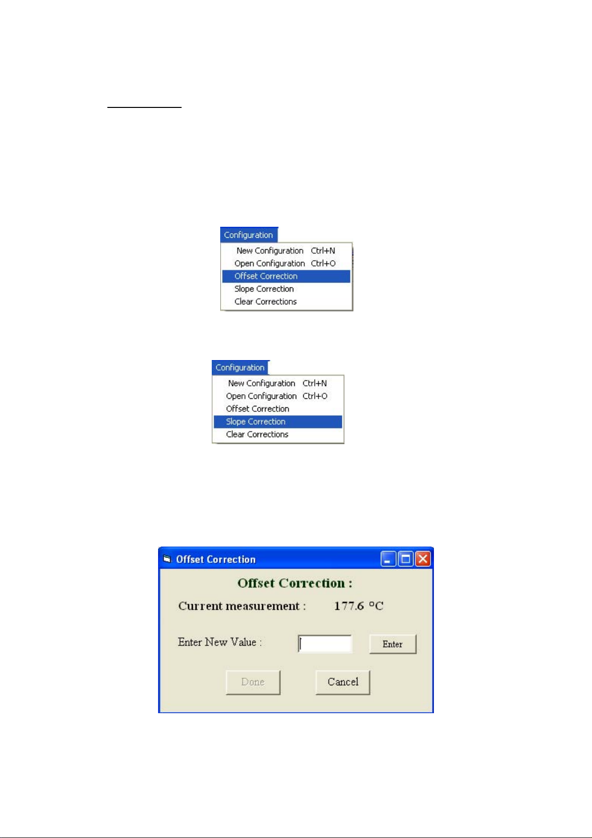
7.1 Offset Corrections
For cases when the TX69 output differs by a fix (offset) error throughout the entire
span, select the “Offset Correction” option from the "Configuration" menu:
The accurate value should be entered.
14
Page 17
At the end of the updating procedure, the following options are
available:
Done - Saves the new contents of the field.
Cancel - Retrieves the previous configuration.
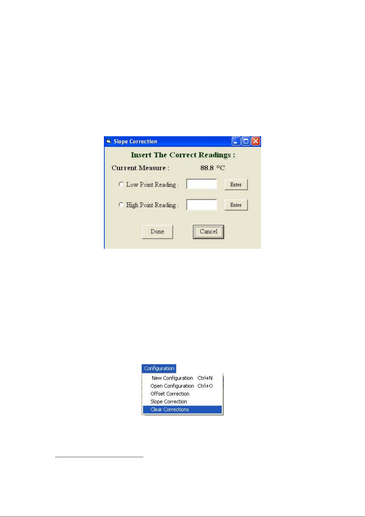
7.2 Slope Correction
For cases when the TX69 should match a different sensor behavior than the standard
sensor's table, select the “Slope Correction” option from the "Configuration" menu:
First set the input to the low point measurement, and then enter the desired reading –
press "Enter". Then set the input to the high point measurement, and then enter the
desired reading – press "Enter"
At the end of the updating procedure, the following options are available:
Done - Saves the new contents of the field.
Cancel - Retrieves the previous configuration.
Clear Corrections:
In order to erase all the corrections and bring the TX69 to its original calibration
select the “Clear Corrections” from the "Configuration" menu.
The “Updating…” window appears on the screen. (The same as the one appears
during the updating process).
4
4
Note that this feature starts automatically if the operator tries to correct sensors’ error, when there is
already other previous configuration of sensors’ error.
15
Page 18
8. ADDITIONAL FEATURES :
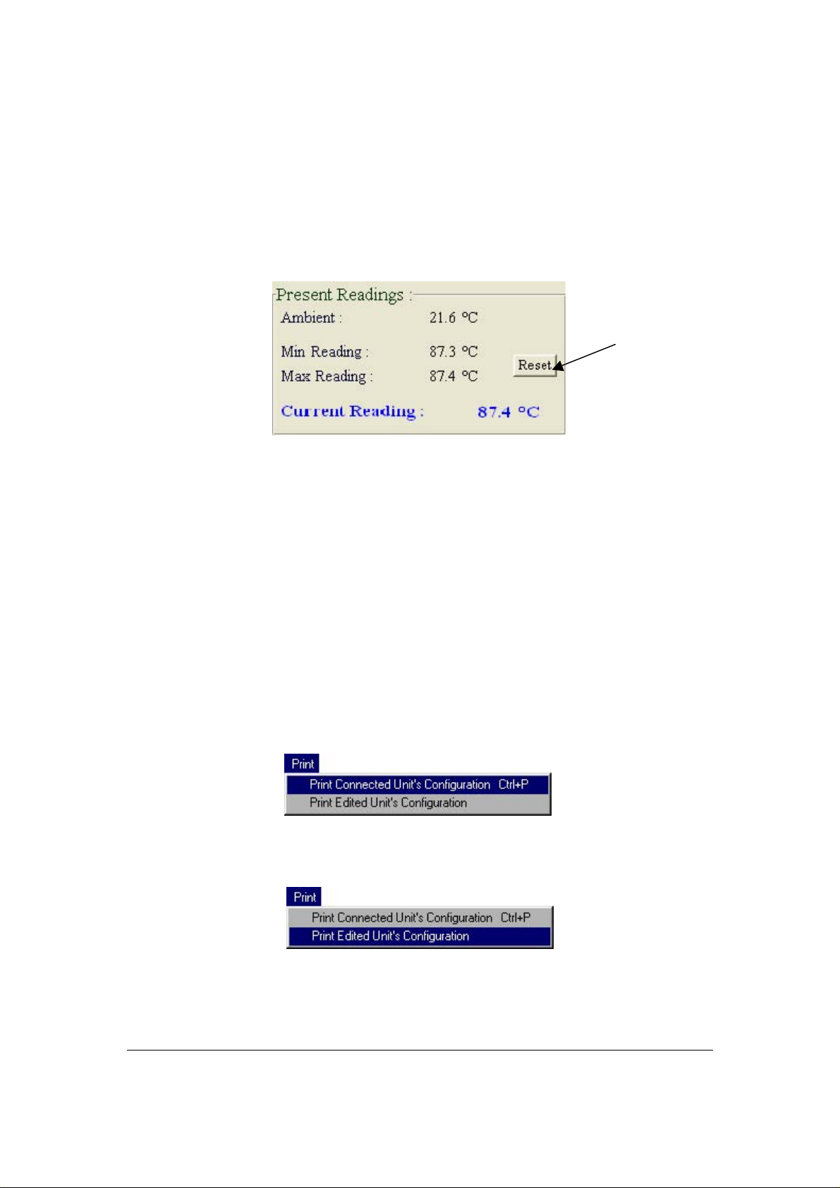
8.1 Resetting The Extreme Measurements :
The Min and Max Readings display the process extreme measurements. This function
is operational only when the unit is not connected to the PC.
Pressing the "Reset" button, clears the reading.
The “Updating…” window appears on the screen.
At the end of the resetting process, the “Min Reading” and “Max Reading” fields
contains extreme readout of -20000 and +20000.
8.2 Print
The system provides the operator to keep an hardcopy archive containing the different
configurations defined by the operator.
There are 2 different types of printing:
• Print Connected Unit’s Configuration - Prints the configuration of
the connected unit.
• Print Edited Unit’s Configuration - Prints the contains of the
Configuration window.
Commencing 1 of the 2 options would open a standard windows printing window :
On any case, before the process starts the system let the operator decide whether to continue or to stay
with the present configuration.
16
Page 19
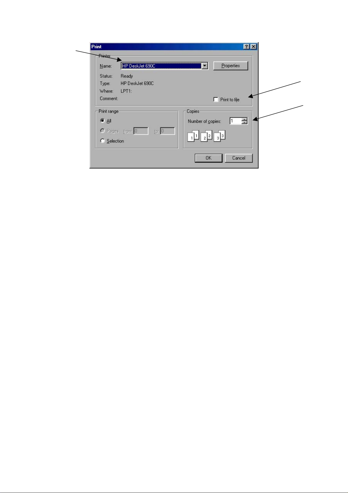
In this window the operator can define a few options:
Selecting the printer that will print the configuration.
Selecting between printing on paper or directly to a file.
Defining how many copies to print.
At the end of the updating procedure, the following options are
available:
Done - Saves the new contents of the field.
Cancel - Retrieves the previous configuration.
17
Page 20

WARRANTY/DISCLAIMER
OMEGA ENGINEERING, INC. warrants this unit to be free of defects in materials and workmanship for a
period of 13 months from date of purchase. OMEGA’s WARRANTY adds an additional one (1) month
grace period to the normal one (1) year product warrant
ensures that OMEGA’s customers receive maximum coverage on each product.
If the unit malfunctions, it must be returned to the factory for evaluation. OMEGA’s Customer Service
Department will issue an Authorized Return (AR) number immediately upon phone or written request
Upon examination by OMEGA, if the unit is found to be defective, it will be
charge. OMEGA’s
including but not limited to
improper repair, or unauthorized modification. This
having been tampered with or shows evidence of having been damaged as a result of excessive corrosion;
or current, heat, moisture or vibration; improper specification; misapplication; misuse or other operatin
conditions outside of OMEGA’s control. Components in which wear is not warranted,
limited to contact points, fuses, and triacs.
OMEGA is pleased to offer suggestions on
OMEGA neither assumes responsibility for any omissions or errors nor assumes liability for any
damages that
OMEGA, either verbal or written. OMEGA warrants only
as s pecifi ed and f ree of defects . OMEGA MAKES NO OTHER
REPRESENT
AND ALL IMPLIED
FI TNESS FOR A PA
LIABILITY: The
OMEGA with respect to this order,
indemnification, strict liability or otherwise, shall not exceed the purchase price of the
co mponent upo n whi ch liabilit y is base d. In no event shal l OM EGA be li able for
consequential, incidental or special damages.
CONDITIONS:
Component” under 10 CFR 21
applications or used on humans. Should any Product(s) be used in or with any nuclear installation or
activity, medical application, used on humans, or misused in any way, OMEGA assumes no
as set forth in our basic
OMEGA and hold OMEGA harmless from any liability or damage whatsoever arising out of the use of the
Product(s) in such a manner
ATIONS OF ANY KIND WHATSOEVER, EXPRESS OR IMPLIED, EXCEPT THAT OF TITLE,
WARRANTY does not apply to defects resulting from any action of the purchaser,
mishandling, improper interfacing, operation outside of design limits,
WARRANTY is VOID if the unit shows evidence of
the use of its various products. However,
result from the use of its products in accordance with information provided by
WARRANTIES INCLUDING ANY WARRANTY OF MERCHANTABILITY AND
RTICULA R PURP OSE AR E HEREBY DISCLAIMED . LIMITATION O F
remedies of purchaser set forth herein are exclusive, and the total liability of
whether based on contract, warranty, negligence,
Equipment sold by OMEGA is not intended to be used, nor shall it be used: (1) as a “Basic
(NRC), used in or with any nuclear installation or activity; or (2) in medical
WARRANTY/ DISCLAIMER language, and, additionally, purchaser will indemnify
.
y to cover handling and shipping time. This
repaired or replaced at no
g
include but are not
that the parts manufactured by it will be
WARRANT IES OR
responsibility
.
RETURN REQUESTS/INQUIRIES
Direct all warranty and repair requests/inquiries to the OMEGA Customer Service Department. BEFORE
RETURNING ANY PRODUCT(S) TO OMEGA, PURCHASER MUST OBTAIN AN AUTHORIZED RETURN
(AR) NU M B ER FROM OM E G A’S C USTOME R S E RV I CE DEPARTMEN T ( IN ORDER T O
PROCESSING DELAYS). The assigned AR number should then be marked on the outside of the retur
package and on any correspondence.
The purchaser is responsible for shipping charges, freight, insurance and proper packaging to prevent
breakage in transit.
WARRANTY RETURNS, please have the
FOR
following information available BEFORE
contacting OMEGA:
1. Purchase Order number under which the produc
was PURCHASED,
2. Model and serial number of the product under
warranty, and
3. Repair instructions and/or specific problems
relative to the product.
OMEGA’s policy is to make running changes, not model changes, whenever an improvement is possible. This affords
our customers the latest in technology and engineering.
OMEGA is a registered trademark of OMEGA ENGINEERING, INC.
© Copyright 2007 OMEGA ENGINEERING, INC. All rights reserved. This document may not be copied, photocopied,
reproduced, translated, or reduced to any electronic medium or machine-readable form, in whole or in part, without the
prior written consent of OMEGA ENGINEERING, INC.
FOR NON-WARRANTY REPAIRS,
for current repair charges. Have the following
information available BEFORE contacting OMEGA
t
1. Purchase Order number to cover the COST
of the repair
2. Model and serial number of the product, and
3. Repair instructions and/or specific problems
relative to the product.
,
consult OMEGA
AVOID
n
:
Page 21

Where Do I Find Everything I Need for
Process Measurement and Control?
OMEGA…Of Course!
Shop online at omega.com
TEMPERATURE
Thermocouple, RTD & Thermistor Probes, Connectors, Panels & Assemblies
Wire: Thermocouple, RTD & Thermisto
Calibrators & Ice Point References
Recorders, Controllers & Process Monitors
Infrared Pyrometers
PRESSURE, STRAIN AND FORCE
Transducers & Strain Gages
Load Cells & Pressure Gages
Displacement Transducer
Instrumentation & Accessories
s
FLOW/LEVEL
Rotameters, Gas Mass Flowmeters & Flow Computers
Air Velocity Indicators
Turbine/Paddlewheel Systems
Totalizers & Batch Controllers
r
pH/CONDUCTIVITY
pH Electrodes, Testers & Accessorie
Benchtop/Laboratory Meters
Controllers, Calibrators, Simulators & Pumps
Industrial pH & Conductivity Equipment
s
DATA ACQUISITION
Data Acquisition & Engineering Software
Communications-Based Acquisition System
Plug-in Cards for Apple, IBM & Compatibles
Datalogging System
Recorders, Printers & Plotters
s
HEATERS
Heating Cable
Cartridge & Strip Heaters
Immersion & Band Heaters
Flexible Heaters
Laboratory Heaters
ENVIRONMENTAL
MONITORING AND CONTROL
Metering & Control Instrumentation
Refractometer
Pumps & Tubin
Air, Soil & Water Monitors
Industrial Water & Wastewater Treatment
pH, Conductivity & Dissolved Oxygen Instruments
s
g
s
M4456/0807
 Loading...